Language selection

Search

Patent 2328779 Summary

Third-party information liability

Some of the information on this Web page has been provided by external sources. The Government of Canada is not responsible for the accuracy, reliability or currency of the information supplied by external sources. Users wishing to rely upon this information should consult directly with the source of the information. Content provided by external sources is not subject to official languages, privacy and accessibility requirements.

Claims and Abstract availability

Any discrepancies in the text and image of the Claims and Abstract are due to differing posting times. Text of the Claims and Abstract are posted:

  • At the time the application is open to public inspection;
  • At the time of issue of the patent (grant).
(12) Patent: (11) CA 2328779
(54) English Title: METHOD FOR STARTING A FUEL CELL SYSTEM, AS WELL AS A FUEL CELL SYSTEM
(54) French Title: PROCEDE PERMETTANT DE FAIRE DEMARRER UN DISPOSITIF A CELLULES ELECTROCHIMIQUES ET DISPOSITIF A CELLULES ELECTROCHIMIQUES
Status: Deemed expired
Bibliographic Data
(51) International Patent Classification (IPC):
  • B60L 11/18 (2006.01)
  • H01M 8/04 (2006.01)
(72) Inventors :
  • STUHLER, WALTER (Germany)
  • WEISS, ALFRED (Germany)
(73) Owners :
  • SIEMENS AKTIENGESELLSCHAFT (Germany)
(71) Applicants :
  • SIEMENS AKTIENGESELLSCHAFT (Germany)
(74) Agent: FETHERSTONHAUGH & CO.
(74) Associate agent:
(45) Issued: 2005-09-20
(86) PCT Filing Date: 1999-04-19
(87) Open to Public Inspection: 1999-10-28
Examination requested: 2003-03-13
Availability of licence: N/A
(25) Language of filing: English

Patent Cooperation Treaty (PCT): Yes
(86) PCT Filing Number: PCT/DE1999/001166
(87) International Publication Number: WO1999/054159
(85) National Entry: 2000-10-16

(30) Application Priority Data:
Application No. Country/Territory Date
198 17 188.9 Germany 1998-04-17

Abstracts

English Abstract


The invention relates to a method for starting
a mobile fuel cell system, in particular for a vehicle,
in which the air which is to be supplied to the system
is conveyed during starting and operation of the system
by a motor-powered compressor (2), in order to ensure
the necessary operating pressure and, if required,
additional humidifying of the air. The motor drive for
the compressor (2) has an electric motor (4, 20) which
is supplied from a mobile starter battery (5) during
the starting phase. The output voltage of the starter
battery (5) is different to the operating voltage at
the output of the fuel cell stack (1) of the fuel cell
system, with a control device (10) being provided
between the output of the starter battery (5) or of the
fuel cell stack (1) and the motor input (8), which
control device (10) interrupts the starting voltage
supplied from the output (6) of the starter battery (5)
and switches over to the output voltage of the fuel
cell stack (1) when the output operating voltage of the
fuel cell stack (1) reaches an adequate level.


French Abstract

L'invention concerne un procédé qui permet de faire démarrer un dispositif mobile à cellules électrochimiques, notamment un véhicule. Selon le procédé, l'air est amené audit dispositif, lors du démarrage et durant le fonctionnement, par un compresseur (2) entraîné par un moteur de façon à fournir la pression de fonctionnement nécessaire et éventuellement à assurer une humidification supplémentaire de l'air. L'entraînement motorisé du compresseur (2) comporte un moteur électrique (4, 20), qui est alimenté durant la phase de démarrage par une batterie de démarrage (5) mobile. La tension de sortie de ladite batterie (5) est différente de la tension de fonctionnement à la sortie de la pile (1) de cellules électrochimiques du dispositif. Un dispositif de commande (10), placé entre la sortie de la batterie de démarrage (5) ou de la pile (1) et l'entrée (8) du moteur, interrompt la tension de démarrage amenée depuis la sortie (6) de ladite batterie (5) lorsqu'une tension de fonctionnement suffisante a été atteinte à la sortie de la pile (1) et commute sur la tension de sortie de cette dernière.

Claims

Note: Claims are shown in the official language in which they were submitted.


-9-

Claims

1. A method for starting a fuel cell system
having a fuel cell stack (1), a compressor (2) for
supplying a working medium to the fuel cell stack (1),
and an electric motor (4, 20) for driving the
compressor (2),
characterized in that the electric motor (4, 20) is
initially fed with current from a starter battery (5),
and then with current from the fuel cell stack (1).
2. The method as claimed in claim 1,
characterized in that the fuel cell, system is a mobile
air and hydrogen system, and in that the fuel cell
system is supplied with air (L) as the working medium
during starting and operation, and in that the air (L)
is conveyed by the motor-driven compressor (2) in order
to ensure the necessary operating pressure and, if
necessary, additional humidifying of the air (L).
3. The method as claimed in claim 1 or 2,
characterized in that the electric motor (4, 20) of the
compressor (2) is supplied from the starter battery (5)
during the starting phase of the fuel cell system.
4. The method as claimed in one of claims 1 to
3,
characterized in that the voltage of the starter
battery (5) is different to the operating voltage of
the fuel cell stack (1).
5. The method as claimed in one of claims 1 to
4,
characterised in that, when the fuel cell stack (1)
reaches an adequate output voltage, a control device
(10) which is located between the output (6) of the
starter


-10-
battery (5) and/or the output (9) of the fuel cell
stack (1) and the motor input (8) interrupts the
starting voltage supplied from the output of the
starter battery (5), and connects the output voltage of
the fuel cell stack (1) to the electric motor (4, 20).
6. The method as claimed in one of claims 1 to
5,
characterized in that the control device (10) comprises
a converter (11, 30), in that the operating voltage of
the electric motor (4, 20) corresponds to the voltage
of the starter battery (5), and in that the converter
(11, 30) regulates the output voltage of the fuel cell
stack (1) down to at least the value of the operating
voltage of the electric motor (4, 20).
7. The method as claimed in claim 6,
characterized in that the rotation speed of the
electric motor (4, 20) is permanently regulated by the
converter (11, 30).
8. The method as claimed in one of claims 1 to
7.
characterized in that the system switches over from the
starter battery (5) to the fuel cell stack (1) as soon
as the output voltage of the fuel cell stack (1) is
higher than the voltage of the starter battery (5).
9. The method as claimed in one of claims 1 to
8.
characterized in that the operating voltage of the fuel
cell stack (1) is approximately twice as great as the
voltage of the starter battery (5).
10. The method as Claimed in one of Claims 6 t0
9,
characterized in that the converter (11) is a
direct-current controller, and the electric motor (4) is a
direct-current motor.


-11-
11. The method as claimed in one of claims 1 to
9,
characterized in that the electric motor (20) is a
synchronous motor or an asynchronous motor which has
two separate winding systems (21, 22), in that the
first winding system (21) is designed for the voltage
of the starter battery (5), and the second winding
system (22) is designed for the operating voltage of
tho fuel cell stack (1), and in that a control device
(10) is provided which comprises a converter (30) which
is preferably in the form of an inverter.
12. The method as claimed in claim 11,
characterized in that the electric motor (20) is
permanently connected to the output (33) of the
converter (30), in that the second winding system (22),
which is designed for the operating voltage of the fuel
cell stack (1), is permanently connected to the output
(33) of the converter (30), and in that the first
winding system (21), which is designed for the voltage
of the starter battery (5), can be isolated from the
voltage sources (1, 5) via disconnection elements (31).
13. The method as claimed in claim 12,
characterized in that the first winding system (21) of
the electric motor (20) is disconnected at the zero
crossing.
14. The method as claimed in one of claims 1 to
13,
characterized in that current is drawn from the starter
battery (5) only until the output voltage of the fuel
cell stack (1) has reached a value which is greater
than the voltage of the starter battery (5).
15. The method as claimed in one of claims 5 to
14,
characterized in that a converter (11, 30) having an
intermediate circuit is used as the control device
(10),


-12-
and in that the operating voltage at the output (9) of
the fuel cell stack (1) is increased continuously, as a
result of which the components in the intermediate
circuit of the converter (11, 30) are raised to a
higher operating voltage.
16. A fuel cell system having a fuel cell stack
(1), having a compressor (2) for supplying a working
medium to the fuel cell stack (1), and having an
electric motor (4, 20) for driving the compressor (2),
characterized in that the electric motor (4, 20) of the
compressor (2) can optionally be operated with current
from a starter battery (5) or with current from the
fuel cell stack (1).
17. The fuel cell system as claimed in claim 16,
characterized in that the fuel cell system is a mobile
fuel cell system, which can be operated with air (L)
arid hydrogen (H2) , for a vehicle propulsion system,
which comprises a number of fuel cells in a fuel cell
stack (1) to which hydrogen (H2) and compressed air (L)
can be supplied via a respective inlet, and in that the
air inlet of the fuel cell stack (1) is connected to
the compressor (2), which is connected to the electric
motor (4, 20) that can be supplied from the starter
battery (5).
18. The fuel cell system as claimed in claim 16
or 17,
characterized in that the input (8) of the electric
motor (4, 20) can be connected or is connected via an
electronic control device (10), which has a converter
(11, 30), not only to the output (6) of the starter
battery (5), but also to the output (9) of the fuel
cell stack (1).
19. The fuel cell system as claimed in claim 18,
characterized in that a switching apparatus (12) is
provided, which is connected electrically upstream of
the input (13) of the converter (11).


-13-
20. The fuel cell system as claimed in claim 19,
characterized in that inputs of the switching apparatus
(12) which are connected to the starter battery (5) or
to the fuel cell stack (1) can be switched over
smoothly.
21. The fuel cell system as claimed in one of
claims 18 to 20,
characterized in that the output (14) of the converter
(11) is permanently connected to the input (8) of the
electric motor (4).
22. The fuel cell system as claimed in one of
claims 16 to 21,
characterized in that the electric motor (20) is in the
form of a synchronous or an asynchronous motor and has
two separate winding systems (21, 22), wherein the
first winding system (21) is designed to be supplied
with a low voltage, and the second winding system (22)
is designed to be supplied with a higher voltage.
23. The fuel cell system as claimed in claim 22,
characterized in that the output (6) of the starter
battery (5) and the output (9) of the fuel cell stack
(1) are permanently connected via decoupling diodes
(27) to the input (25, 26) of a converter (30).
24. The fuel cell system as claimed in claim 22
or 23,
characterized in that the first winding (21), which is
designed for low voltage, can be disconnected.
25. The fuel cell system as claimed in claim 24,


-14-
characterized in that disconnection elements (31) are
provided, and are integrated in the electric motor
(20).

Description

Note: Descriptions are shown in the official language in which they were submitted.


c:l ~ UU UV 1J.1-! tri.1 V11 JJiOULVU l~lt.7 11~t11v.5Lr111UW ,~ t'Lvr ~Ul/,)
GR 98 P 8542 P
Description
Method for starting a fuel cell system, as well as a
fuel cell system
The invention relates to a method for starting
a fuel cell system having a fuel cell stack, a
compressor for supplying a working medium to the fuel
cell stack, and an electric motor for driving the
compressor. The invention also relates to a fuel cell
system having a fuel cell stack, a compressor for
supplying a working medium to the fuel cell stack, arid
an electric motor for driving the campres3or.
DE 43 22 767 C2 discloses a fuel cell system
and a method for starting a duel cell system of the
type mentioned init~.ally. The fuel cell system
described in this document is an air and hydrogen
system. A compressor which can be powered by an
electric motor is provided to compress the air in the
known system. The electric motor is supplied from a
mobile startez battery during the starting phase.
Since, in the prior art, the output voltage of
the starter battery is different to the operating
voltage of the fuel cell stack of the fuel cell system,
which is present at the output of the fuel, cell stack,
a separate electric motor, which is designed for the
higher voltage of the fuel cell stack, is provided as
well as the starter motor i:1 the prior art. Such an
apparatus is relatively complex since it requires two
separate electric motors, which must be coupled to the
compressor, occupying space and volume.
The invention is based on the object of
specifying a method for starting a fuel cell system, in
which the operation of the compressor is simplified,
and which
CA 02328779 2000-10-16


CA 02328779 2005-03-17
20365-4305
2
requires less design complexity and occupies less space for
the fuel cell system.
In accordance with one aspect of this invention,
there is provided a method for starting a fuel cell system
having a fuel cell stack, a compressor for supplying a
working medium to the fuel cell stack, and an electric motor
for driving the compressor, characterized in that the
electric motor is initially fed with current from a starter
battery, and then with current fr~~m the fuel cell stack.
The essence of the invention is to switch the
power supply for the electric motor from the starter battery
to the fuel cell stack and, if ne~:essary, back again. The
switching process takes place when the voltage at the output
of the fuel cell stack reaches an adequate level. The
electrical connection between the output of the starter
battery and the motor input is ini:errupted, and the motor
input is switched to the output voltage of the fuel cell
stack. A fuel cell stack is also referred to as
Brennstoffzellan-Stack [fuel cell stack] in the German
specialist literature.
In a development of the invention, the fuel cell
system is a mobile air and hydrogE:n system, in particular
for a vehicle, such as a construction industry vehicle, a
vehicle for use indoors, a bus or the like. The fuel cell
system is supplied with air as thE: working medium during
starting and operation, and the ai.r is conveyed by the
motor-driven compressor in order t.o ensure the necessary
operating pressure and, if necesss.ry, additional humidifying
of the air. One suitable fuel cell system is a PEM fuel
cell system with PEM fuel cells. In this case, PEM stands
for proton exchange membrane or else polymer electrolyte
membrane.


CA 02328779 2005-03-17
20365-4305
2a
During the starting phase of the fuel cell system,
the electric motor of the compressor is advantageously
supplied from

i ua uu t~ : to rep ut r a.s~~~u~au nna tn~v~Lc~mw~ ra.Wl uu5
GR 98 P X542
- ~ _
the starter battery. During the starting phase, the
fuel cell block does not yet develop any voltage, or
does not yet develop the necessary voltage, in order to
operate the electric motor.
Tn an advantageous development of the
invention, a control device is provided for switching
the power supply of the electric motor, which control
device interrupts the electrical connection between the
output of the starter battery and the motor input and
switches over the motor input to the output voltage of
the fuel cell stack when the output voltage of the fuel
cell stack reaches an adequate level.
2~he operating voltage of the electric motor
advantageously corresponds to the voltage of the
Z5 starter battery, and the control device advantageously
comprises a converter which regulates the output
voltage of the fuel cell stack down to the operating
voltage of the electric motor, or less. A current
regulator is able to regulate the output voltage of the
fuel cell stack down to the operating voltage of the
direct-current motor and, in the process, also
advar_tageously maintain this direct-current motor at a
constant rotation speed.
The control device advantageously has two
functions: firstly the selection and switching of the
supplied operating voltage for the electric motor
during the starting phase and during the operating
phase of the system. And secondly, the advantageous
permanent regulation of the motor, which is important
for optimized operation of the fuel cell stack, since
the compressor is to provide reproducible and
advantageously optimized power levels.
The switching from the starter battery to the
output of thN fuel cell stack advantageously takes
place when the output voltage of the fuel. cell stack is
higher than the voltage of the starter battery since,
in this case, the converter just has to regulate the
output voltage 1~vel of th9 fuel cell Stack downward.
CA 02328779 2000-10-16

~mua uu ta:lu t'tib UllaJ~ltiULfSU litt~J liCtll'IJLt111U1V7 YL4 ~luuo
' GR 98 P 8542
- ~ _ g _
The output voltage of the fuel cell stack is
advantageously approximately twice as great as the
voltage of the starter battery. This refinement of the
invention allows the electrical and electronic
components of the converter still to have small
dimensions for a mobile system.
A further advantage can be achieved by the
converter being a direct-current controller (DC/DC
controller) and the eJ.ectric motor being a direct
current motor.
In an alternative refinement of the invention,
the electric motor is a synchronous motor or an
asynchronous motor and the control device comprises a
converter which is in the form of an inverter, for
example a DC/three-phase AC inverter. furthermore, the
electric motor has two separate windzng systems, with
the first winding system being designed for the voltage
of the starter battery, and the second winding system
being designed for the higher voltage of the fuel cell
stack.
The control device also provides the motor
regulation and the switching and selection of the two
voltage sources, The first winding, which is designed
for the voltage of the starter battery, can be isolated
from the voltage sources via disconnection elements.
The disconnecr_ion elements can be controlled by the
switching apparatus, in the form of a DC/three-phase AC
controller. The second winding system, which is
designed for the operating voltage of the fuel cell
stack, is continuously connected to the controller
output.
Current is expediently drawn from the starter
battery only until the voltage level at.the output of
the fuel cell stack has reached a changeover value,
which can be preset. This is greater than the voltage
level of the stazter battery.
CA 02328779 2000-10-16


CA 02328779 2005-03-17
20365-4305
Tn order to protect the electrical components and
the motor, the first winding system of the electric motor is
expediently disconnected at the zero crossing.
In accordance with another aspect of this
5 invention, there is provided a fuel cell system having a
fuel cell stack, having a compressor for supplying a working
medium to the fuel cell stack, an~~ having an electric motor
for driving the compressor, characterized in that the
electric motor of the compressor ~~an optionally be operated
with current from a starter battery or with current from the
fuel cell stack.
The fuel cell system is advantageously a mobile
fuel cell system, which can be opE~rated with air and
hydrogen, for powering vehicles. The fuel cell system
comprises at least one fuel cell stack, which in turn
comprises a number of fuel cells. The fuel cells are
supplied, for example, with hydrogen and compressed air via
a respective inlet. An air comprEassor is connected to the
inlet of the fuel cells and has a motor drive with an
electric motor which can be suppl~.ed from a starter battery.
In a development of the invention, the motor is
connected to the power sources vii. an electronic control
device. The control device has a converter having an
intermediate circuit, that is, for example, a direct-current
controller or an inverter, depending on whether the electric
motor of the compressor is a direct-current motor, an
alternating-current motor, or a three-phase motor.
Advantageously, apart from its control function,
the control device also has a switching function and thus
has a switching apparatus, which is connected electrically
upstream of the input of the converter.


CA 02328779 2005-03-17
20365-4305
5a
The output of the converter is expediently
permanently connected to the input of the electric motor.

27~U9 'UO l5:ld FA.Y 1t1753.~8t)~'8u ItVVS 1'ItAN~LAlI~iIV~ YW: ~PIU08
GR 98 p 8542 P
- 6 -
If the control device is in the form of an
inverter, fox example a DC/three,phase AC controller,
both the output of the starter battery and the output
of the fuel cell stack can be permanently connected via
decvupling diodes to the input of the DC/thxee-phase AC
controller.
In a further advantageous refinement of the
invention, the electric motor (which is in the form of
a three-phase motor) of the compressor has two separate
winding systems. In this case, the first winding system
is designed to be supplied with the low voltage of the
starter battery, and the second winding system is
designQd to be supplied with a higher voltage, namely
the voltage of the fuel cell stack.
The first winding system, which is designed for
the lower voltage, of the electric motor can
expediently be disconnected as soon as a changeover
voltage level, which could be dangerous to the
sensitive first winding system, is reached. The actual
disconnection apparatus is advantageously integrated in
the electric motor, or the compressor motor.
The invention will be explained in mare detail
with reference to exemplary embodiments in the figures
of the drawing, in which:
Figure 1 shows a fuel cell system having a direct-
current compressor motor;
Figure 2 shows a fuel cell system having a three-phase
synchronous motor or a three-phase
asynchronous motor.
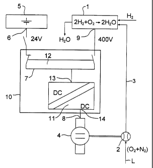
The mobile fuel cell system, which is first of
all illustrated only schematically and with the
fundamental components relating to the invention in
figure 1, comprises a number of fuel cells, which are
configured and illustrated aS a fuel cell stack 1.
Compressed air is supplied to the fuel cell stack 1 via
a compressor 2 and a line 3.
CA 02328779 2000-10-16

zmua uu .t5:ii rnx uut5~4~uz~u xws mc~uv~~muu~ rL~ ~uua
_ GR 98 P 8542 P
The compressor 2 is driven by an electric motor
4 which is supplied from a starter battery 5 during the
starting or run-up phase of the fuel cell system, the
output 6 of which starter battery 5 provides an
operating voltage of 24 V, which is supplied to the
motor input 8 via a cable 7. The motor input 8 is rot
only connected to the output 6 of the starter battery
5, but can also be connected to the output 9 of the
fuel cell stack 1. For this purpose, a control device
10 is provided, which has a converter 11. The converter
11 is a direct-current controller (DC/DC controller)
for the electrzc motor 4 which is in the form of a
direct-current motor) of the compresspx 2.
The switching from the output 6 of the starter
battery 5 to the output 9 of the Fuel cell stack 1
takes place via, a switching apparatus 12, whose
switching response can be controlled by an output 13 of
the control device 10. The output 14 of. the converter
11 is permanently connected to the input 8 of the
electric motor 4.
Figure 2 likewise illustrates a fuel cell
system. However, the electric motor 20 for powering the
compressor 2 is not a direct-current motor, but a
three-phase synchronous motor or a three-phase
asynchronous motor and has two separate winding systems
21, 22, The first winding system 2.1 is designed to be
supplied with the output voltage from the starter
battery 5, and the second winding 22 is designed to be
supplied with the higher voltage from the fuel cell
stack 1.
The output voltages at the outputs 6 and 9 of
the voltage sources differ considerably in the
exemplary embodiment illustrated in Figure 2. The
starter battery 5 supplies an output voltage of, ~or
example, 48 V. The fuel. cell stack 1 is designed to
produce the operating voltage of 400-680 v at its
output 9.
CA 02328779 2000-10-16

27/09 ' 00 15 :17 FAX 0175348028U RWS '1'RANSLA'1'IUNS Y.LC ~I OlU
GR 98 P 8542 p
g _
Decoupling diodes 27 are connected in the power
cables between the output 6 of the startex battery 5
and the output 9 of the fuel cell stack 1 and the
inputs 25 and 26 of the control de~rice Z0. The control
device 10 has a converter 30 for the electric motor 20,
which is in the form of an in~rerter (DC/three-phase AC
controllery.
Disconnection elements 31 are also integrated
in the area of the electric motor 20 and can be
l0 activated via an output 32 of the control device 10 to
isolate the winding system 21 from the output 33 of the
converter 30. This is done when the fuel cell stack 1
reaches a voltage which is considerably higher than
that of the starter battery. The fuel cell stack then
supplies the direct-current section of the control
device 10.
CA 02328779 2000-10-16

Representative Drawing
A single figure which represents the drawing illustrating the invention.
Administrative Status

For a clearer understanding of the status of the application/patent presented on this page, the site Disclaimer , as well as the definitions for Patent , Administrative Status , Maintenance Fee  and Payment History  should be consulted.

Administrative Status

Title Date
Forecasted Issue Date 2005-09-20
(86) PCT Filing Date 1999-04-19
(87) PCT Publication Date 1999-10-28
(85) National Entry 2000-10-16
Examination Requested 2003-03-13
(45) Issued 2005-09-20
Deemed Expired 2008-04-21

Abandonment History

There is no abandonment history.

Payment History

Fee Type Anniversary Year Due Date Amount Paid Paid Date
Registration of a document - section 124 $100.00 2000-10-16
Application Fee $300.00 2000-10-16
Maintenance Fee - Application - New Act 2 2001-04-19 $100.00 2001-03-19
Maintenance Fee - Application - New Act 3 2002-04-19 $100.00 2002-03-15
Request for Examination $400.00 2003-03-13
Maintenance Fee - Application - New Act 4 2003-04-21 $100.00 2003-03-18
Maintenance Fee - Application - New Act 5 2004-04-19 $200.00 2004-03-10
Maintenance Fee - Application - New Act 6 2005-04-19 $200.00 2005-03-11
Expired 2019 - Filing an Amendment after allowance $400.00 2005-03-17
Final Fee $300.00 2005-07-11
Maintenance Fee - Patent - New Act 7 2006-04-19 $200.00 2006-03-10
Owners on Record

Note: Records showing the ownership history in alphabetical order.

Current Owners on Record
SIEMENS AKTIENGESELLSCHAFT
Past Owners on Record
STUHLER, WALTER
WEISS, ALFRED
Past Owners that do not appear in the "Owners on Record" listing will appear in other documentation within the application.
Documents

To view selected files, please enter reCAPTCHA code :


To view images, click a link in the Document Description column. To download the documents, select one or more checkboxes in the first column and then click the "Download Selected in PDF format (Zip Archive)" or the "Download Selected as Single PDF" button.

List of published and non-published patent-specific documents on the CPD .

If you have any difficulty accessing content, you can call the Client Service Centre at 1-866-997-1936 or send them an e-mail at CIPO Client Service Centre.


Document
Description 
Date
(yyyy-mm-dd) 
Number of pages   Size of Image (KB) 
Claims 2000-10-16 6 204
Representative Drawing 2001-02-13 1 5
Abstract 2000-10-16 1 32
Description 2000-10-16 8 340
Drawings 2000-10-16 2 29
Cover Page 2001-02-13 2 67
Description 2005-03-17 10 344
Representative Drawing 2005-08-25 1 7
Cover Page 2005-08-25 2 48
Assignment 2000-10-16 4 133
PCT 2000-10-16 14 480
Prosecution-Amendment 2003-04-15 1 34
Prosecution-Amendment 2003-03-13 1 49
Prosecution-Amendment 2005-04-12 1 15
Prosecution-Amendment 2005-03-17 5 133
Correspondence 2005-07-11 1 29