Note: Descriptions are shown in the official language in which they were submitted.
CA 02328925 2000-10-16
WO 99/54971 PCT/GB99/01105
OPTICAL FIBRE LASER
This invention relates to optical fibre lasers.
Optical fibre grating lasers are attractive alternatives to the already well
established semiconductor technology because they are cheaper to manufacture,
exhibit narrow line width for ultra high resolution sensing and excellent
wavelength
stability provided by the grating. Furthermore they are fibre compatible,
making all-
fibre systems for telecornmunication possible.
Of the fibre lasers demonstrated to date the simplest is the all-fibre grating
DFB (distributed feedback) or DBR (distributed Bragg reflector) laser.
Demonstrations of DFB fibre lasers of different cavity configurations and pump
schemes have been reported on several occasions [1-3]. The first of these
demonstrations showed lasing in two orthogonal polarisation modes. Later
publications of DFB lasers claimed to provide a single polarisation output,
but none
has appeared to demonstrate a good qualitative understanding of the
requirements for
truly single mode output (single frequency and single polarisation).
Of the previously reported writing techniques one publication claims to
introduce what is believed to be a birefringent ir-phase-shift in the centre
of the
structure [4] caused by post-processing with high intensity pulses provided by
excimer
laser I7V-sources (193 nm and 248 nm). The birefringent phase shift will then
apply
more to one polarisation than the other, hence causing that polarisation mode
to reach
the threshold for lasing before the other mode.
Twisting of the DFB fibre lasers and thereby an introduction of a circular
birefringence has also been shown to cause the fibre laser to operate in a
single
polarisation [5]. This state of operation is then a function of the fibre
twist and
therefore the amount of circular birefringence introduced in the cavity.
Furthermore
Hi-Bi fibres have been shown to cause a significant [6] discrimination between
the
two polarisation modes with the result of allowing only one of the modes to
lase.
However, there is still a need for a technique for generating robustly single
polarisation DFB lasers.
This invention provides a method of fabricating a substantially single-
polarisation optical fibre laser, the method comprising the step of exposing
an optical
CA 02328925 2000-10-16
WO 99/54971 PCT/GB99/01105
2
fibre to a transverse writing light beam to form a grating structure in a
section of the
optical fibre, the writing light beam being polarised in a direction not
parallel to the
axis of the section of optical fibre so that the induced grating structure has
a different
grating strength for two orthogonal polarisation modes of the fibre, the
grating
structure comprising a discrete phase shift which is substantially identical
for the two
orthogonal modes.
In embodiments of the invention, by writing substantially an entire fibre
laser
with UV-light polarised perpendicular (or at least non-parallel) to the fibre
axis, a
difference in grating strength between the two orthogonal modes of the fibre
is
introduced. This provides strong polarisation mode discrimination and so a
robust
single polarisation fibre laser operation can be achieved. We show lasers of
length
5 cm and of approximate grating strengths (KL) of -- 8. The lasers have a
discrete
i-phase shift in the structure off-centre by 5 mm giving a ratio of grating
strength
ratio of 2:3 on either side of the phase shift.
Optical phase conjugation has been attracting considerable attention, because
of its application in the compensation of chromatic dispersion and
nonlinearities in
optical fibre communication systems using midspan spectral inversion (MSSI)
technique[10], [11], and also because of its application in wavelength
conversion
which is essential in wavelength-division multiplexed (WDM) optical networks.
It has been conventionally accomplished by four-wave mixing (FWM) in a
dispersion-shifted fibre (DSF) or a semiconductor optical amplifier (SOA), in
which
the optical signal is mixed with an externally injected pump light through a
fibre
coupler, and fed into a DSF or an SOA to generate a wavelength converted
conjugate
light. The signal and pump polarisation states must be aligned to get maximum
conversion efficiency, which is generally not practical since any signal light
polarisation fluctuation will affect the power of the conjugated light.
Two solutions have been proposed to achieve polarisation independence in the
device. These are: (i) a polarisation-diversity arrangement [12], [13]; and
(ii)
injection of two orthogonally polarised pump lights[14], [15]. However, they
add
more complexity in the phase conjugator / wavelength converter.
FWM in a distributed-feedback (DFB) semiconductor laser [16] is attractive
because it does not require external injection of the pump light, but its
polarisation
CA 02328925 2000-10-16
WO 99/54971 PCT/GB99101105
3
independent implementation requires a phase-diversity arrangement [17].
The invention also provides an optical phase conjugator comprising:
one or more in-line optical fibre lasers for generating two substantially
orthogonally polarised pump light beams; and
a non-linear mixing waveguide for receiving and mixing the pump beams with
an input signal beam.
In this aspect of the invention, a novel phase conjugation and/or wavelength
conversion technique by FWM is provided using orthogonally polarised pump
lights -
from inline fibre lasers. Embodiments of this technique feature polarisation
independent operation and simple configuration without the need for external
injection
of pump light.
Further aspects and features of the invention are defined in the appended
claims.
Embodiments of the invention will now be described, by way of example only,
with reference to the accompanying drawings in which:
Fig. 1 illustrates the output spectrum of a single polarisation and single
frequency DFB laser with 20 mW pumped power cQ 980 nm;
Fig. 2 illustrates the so-called Poincare sphere output representation of the
laser of Fig. 1;
Fig. 3a schematically illustrates the fabrication process;
Fig. 3b illustrates the use of such a laser as a frequency standard source;
Fig. 4a is a schematic diagram illustrating a phase conjugator / wavelength
converter using a dual-polarisation fibre DFB laser;
Fig. 4b is a schematic diagram illustrating a phase conjugator / wavelength
converter using two single-polarisation fibre DFB lasers;
Figs. 5a and 5b illustrate the output optical spectra of the phase conjugator
/ wavelength converter of Fig. 4a (using a dual-polarisation fibre DFB laser),
where:
the fibre DFB laser operates at dual polarisations (Fig. 5a); and
the fibre DFB laser operates at a single polarisation (Fig. 5b);
Figs. 6a and 6b illustrate the output optical spectra of the phase conjugator
/ wavelength converter of Fig. 4b (using two single-polarisation fibre DFB
lasers),
where:
CA 02328925 2006-12-22
-4-
the polarisation states of the two pump lights are orthogonal (Fig. 6a);
the polarisation states of the two pump lights are aligned (Fig 6b); and
Fig. 7 shows a monitoring and feedback arrangement for providing
stability in the wavelength of two outputs of a laser.
Theoretical background
Threshold and lasing conditions of DFB fibre lasers are functions of the
grating strength (KL) where K is the coupling coefficient and L is the length
of the
grating, and the grain available in the feedback structure.
For the core of an optical fibre to be photosensitive to UV light a certain
amount of defects, or so-called Germano-Silica wrong bonds, must be present.
The molecular characteristics of the wrong-bonds makes them susceptible for
UV-Iight at a certain wavelength (e.g. 244 nm) to break the bond between them.
The presence of wrong-bonds in the core of an optical fibre causes a stress
that
ideally should be isotropic. The presence of initial birefringence as is the
case in
most fibres however suggests a slightly anisotropic nature of the defects
possibly
generated by the drawing process of the fibres. The wrong-bond breakage
introduced by the UV exposure causes a stress relief causing the refractive
index
to rise in the regions of the relief. A selective Ge-Si wrong-bond breakage
therefore mainly will cause wrong-bonds polarised parallel to the polarisation
of
the light to be broken, and as a result an anisotropic grating will be created
in
the core-region of the fibre.
Experimental set-ug
The experimental set-up used to fabricate a prototype embodiment will
now be described.
The DFB fibre lasers are written in a Deuterium loaded Er3+:Yb3+-doped
fibre, to achieve increased pump absorption, with characteristics described
elsewhere [8]. An intra-cavity frequency doubled Ar-ion laser operating CW at
244 nm with 100 mW output is used as the UV source. The grating forming the
DFB laser was written using techniques and apparatus described in
GB9617688.8, but other known techniques could instead be used. The initial
horizontal linearly polarisation state of the laser was flipped to a vertical
linearly polarised state using a A/2-wave plate. The DFB grating was
written with a Tr- phase shift (identical for both polarisations) off-centre
[9] by 10% in order to maximise the output to one side of the laser. Up to 50
CA 02328925 2000-10-16
WO 99/54971 PCT/GB99/01105
mW of light from a 980 nm diode was used as pump light. The laser was forward
pumped and the polarisation state of the prototype laser was analysed using a
HP
8905B polarisation analyser. The phase shift could of course have been
different, for
example many multiples of 7r.
5
Results for Prototype Laser
Fig. 1 shows the output spectrum of a 5 cm long single frequency, single
polarisation prototype DFB fibre laser pumped with 20 mW @ 980 nm. The
linewidth of the laser was measured to be as low as 3 kHz. An output power
ratio
of 30 dB between the output ends was observed. Being properly temperature
stabilised the laser showed stable output power (3.1 dBm 0.05 dBm) for - 50
mW
pump @ 980 nm and stable single polarisation operation over a period of hours.
Fig.
2 shows the Poincare sphere output of the laser and shows that the degree of
polarisation is 1, indicating single polarisation operation. The laser was
also pumped
with 1480 nm and showed despite the lower output power also single
polarisation
output.
The laser written with the UV light polarised orthogonal to the fibre axis
were
tested against a laser written with a birefringent phase-shift (only
orthogonal polarised
UV writing beam in the phase-shift region). as has been the only recently
demonstrated writing procedure. See for example reference [20], where a two-
step
process is required to achieve a working single polarisation laser, and the
process is
subject to degradation as the tuned phase shift decays in time. We found that
the all
birefringent laser showed more stable single polarisation operation than the
birefringent phase-shift laser. In particular for higher pump powers showed
the
birefringent phase-shift DFB occasional dual polarisation mode operation.
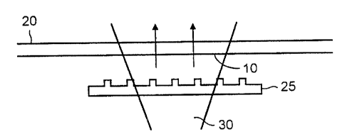
The fabrication process is summarised in Fig. 3a, which illustrates a section
10 of a photosensitive optical fibre 20 being exposed via a phase mask 25 to a
writing
light beam 30 which (in this example) is polarised substantially orthogonally
to the
axis of the section 10.
Fig. 3b illustrates an application of such a laser as part of a frequency
standard device. If the laser is arranged to operate simultaneously at two
wavelengths
but one polarisation then these wavelengths Xl and X2 will be separated by 0X.
This
CA 02328925 2000-10-16
WO 99154971 PCT/GB99/01105
6
can be achieved by overlaying two DFB grating structures or by writing
simultaneously as a Moire phase shifted structure. This difference can be
detected
as an RF beat frequency between the two output wavelengths.
It can easily be shown that AA is proportional to Xl (or X2). So (as
illustrated
in Fig. 7) by monitoring AA using an optical detector 200 and an RF frequency
detector and applying the result via a feedback circuit 210 (e.g. comparing 0X
with
a reference RF signal RF,ef) to a wavelength control of the laser 220
operation (e.g.
a temperature control), great stability in the wavelength of the two outputs
of the laser
can be achieved.
A further application of such a laser will now be described.
Figs. 4a and 4b show the configuration of a phase conjugator / wavelength
converter. The converter uses FWM pump sources 100, 110, 120 which are Er3 +
:Yb3+ fibre DFB lasers [18] pumped with 980nm 100mW laser diodes (LD's).
Preferably the lasers are fabricated as described earlier.
To achieve polarisation independence, the FWM pump lights should preferably
be orthogonally polarised at equal powers [14], [15], so these embodiments use
either
(a) a dual-polarisation fibre DFB laser (Fig.4(a)), or (b) two single-
polarisation fibre
DFB lasers cascaded through a polarisation controller (PC) 130 (Fig.4(b)).
Since the fibre DFB lasers are transparent at the signal wavelength, the
signal
and the DFB generated FWM pump lights are combined through direct injection of
the signal light into one end of the fibre DFB laser. This eliminates the need
of a
polarisation combiner and a signal/ pump coupler as required in a conventional
polarisation independent device. After amplification by an Er3 +-doped fibre
amplifier (EDFA) 140, the signal and pump lights are launched into a
dispersion
shifted fibre (DSF) 150, generating a conjugate light which is insensitive to
the signal
polarisation owing to the two orthogonally polarised pump lights. Optical
isolators
160 are also used to prevent unwanted reflections.
Figs. 5a and 5b show the output optical spectra of the phase conjugator/
wavelength converter using a dual-polarisation fibre DFB laser in Fig.4(a).
The fibre
DFB laser is 5cm in length, operating at 1548._7nm in two orthogonal
polarisations
separated by about 0.8GHz, due to the birefringence in the fibre DFB
resonator, for
this "imperfect" (i.e. practical prototype) laser. The optical powers of the
two
CA 02328925 2000-10-16
WO 99/54971 PCT/GB99/01105
7
polarisations are slightly different at the "free-running state", but they can
be changed
by applying a stress at the mid-point of the fibre DFB laser as a result of
the
anisotropic phase shift induced in the two birefringent axes. By proper
adjustment
of the strength, the orientation and the position of the stress, we could
force it operate
either in two polarisations with equal powers, or in a single polarisation.
The half-
width of the unpumped DFB resonator stop band is measured to be about 0.2nm.
The pass band insertion loss of the DFB laser module including two isolators
is about
2.7dB. This can be reduced to be as low as 1dB with better components and
splices.
A tuneable single frequency laser operating at 1550.5nm is used as a signal
source,
and a llkm-DSF with zero-dispersion wavelength at 1548nm is used as a non-
linear
FWM media. The output spectrum is measured using an optical spectrum analyser
(OSA) (with 0.08nm resolution) with scanning with a maximum hold trace (solid)
and
a minimum hold trace (dashed). The signal polarisation state is varied
arbitrarily
over all states using a PC throughout the measurement. Figure 5(a) shows the
output
spectrum when the fibre DFB laser operates at dual polarisations. As expected,
nearly polarisation independent phase conjugation was realised. Remaining
polarisation dependency is about 0.5dB. When the fibre DFB laser operates at a
single polarisation (Fig.5(b)), the conjugate light suffered large fading over
30dB.
Although the single polarisation lasers in this example did not employ the new
fabrication technique described above, in other embodiments such a technique
is used
and provides associated benefits.
It should be noted that this particular example of dual-polarisation fibre DFB
laser can not be used with the signal bit-rate of higher than 400Mbit/s,
because the
signal bit rate must be less than half of the frequency separation of two pump
lights[15]. The frequency separation can be expanded to more than 40GHz using
a
highly birefringent Er 3+ :Yb3+ fibre[18].
Figs. 6a and 6b show the output optical spectra of the phase
conjugator/ wavelength converter using two single-polarisation fibre DFB
lasers
cascaded through a PC, as shown in Fig.4(b). The fibre DFB lasers are
operating
at 1548.7nm (pump 1) and 1550nm (pump 2) in a single polarisation using the
above
stress method. Incident FWM pump powers into the DSF are set to be equal by
adjusting respective 980nm pump powers of the fibre DFB lasers. Note that the
CA 02328925 2000-10-16
WO 99/54971 PCT/GB99/01105
8
isolators before and after the PC are not essential. Fig. 6(a) is when the
polarisation
states of two pump lights are set to be orthogonal by adjusting the PC between
the
two fibre DFB laser modules. The PC was actually set to minimise the mixing
products between pump I and pump 2 appearing at 1547.4nm and 1551.3nm. The
signal wavelength is set at 1549.5nm between pump 1 and pump 2. In this case,
many mixing products are generated owing to the completely non degenerate FWM
process, and the phase conjugate components to the signal appear at 1547.9nm
conjugate 1, 1549.3nm conjugate 2, and 1550.5nm (conjugates). A solid trace is
when conjugate 1 reaches a maximum, and a broken trace is when it reaches
minimum. It is observed that conjugate 2 is polarisation independent, and one
of
conjugate 1 and conjugate 3 reaches maximum when the other reaches minimum.
The remaining polarisation dependency of conjugate 2 is about 0.5dB. Figure
6(b)
is when the polarisation states of two pump lights are set to be aligned to
maximise
the mixing products between pump 1 and pump 2. Conjugate 2 is found to have a
large polarisation dependency over 20dB, although the maximum conversion
efficiency is improved by 5.3dB compared to that in Fig.6(a), which agrees
well with
the theoretical value of 6dB. The signal wavelength can be set far from pump
wavelengths, but the conversion efficiency becomes poor due to the non ideal
zero-
dispersion wavelength of the DSF.
In summary, a novel technique for optical wavelength conversion and
phase, conjugation by fibre FWM using inline fibre DFB lasers as orthogonally
polarised pump sources has been described. It features substantially
polarisation
independent operation and simple configuration without the need for a
polarisation
combiner and a signal/ pump coupler as required in a conventional polarisation
independent device. Polarisation independent operation of the phase
conjugator/wavelength converter has been described, to achieve a polarisation
dependency as low as 0.5dB. It is also possible to integrate the fibre DFB
laser
module into an EDFA. Furthermore, this technique is applicable to FWM in an
SOA
or in a chalcogenide fibre as well as in a DSF.
CA 02328925 2000-10-16
WO 99/54971 PCT/GB99/01105
9
PUBLICATION REFERENCES
[1] KRINGLEBOTN, J T. et al: Optics Lett., 19, pp. 2101-2103, 1994.
[2] ASSEH, A. et al: Electron. Lett., 31, (9), pp. 969-970, 1995.
[3] LOH, W H. et al: Electron. Lett., 31, (17), pp. 1440-1442, 1995.
[4] HLTBNER, J. et al: Electron. Lett., 33, (2), pp. 139-140, 1997.
[5] HARUJUNIAN, Z. E. et al: Electron. Lett., 32, (4), pp. 346-348, 1996.
[6] DOUAY, M. et al: IEEE Photon., Technol., Lett., 4, pp. 844-846, 1992.
[7] NIAY, P. et al: IEEE Photon., Technol., Lett., 7, (4), pp. 391-3.93, 1995.
[8] DONG, L. et al: Optics Lett., 22, (10), pp. 694-696, 1997.
[9] LAURIDSEN, V C. et al: Proceedings to ECOC'97, 3, pp. 39-42, Session
WE1C, Edinburgh, UK, 1997.
[10] ELLIS, A et al, Electron. Lett., 31, (4), pp.299-301, Feb. 1995.
[11] ROYSET, A et al, IEEE Photon. Technol. Lett., 8, (3) pp.449-451, Mar.
1996.
[12] HASEGAWA, T et al, IEEE Photon. Technol. Lett., 5, pp.947-949, Aug.
1993.
[13] LACET, J P R et al, IEEE Photon. Technol. Lett., 9, (10), pp.1355-1357,
Oct. 1997.
[14] JOPSON R M et al, Electron. Lett., 29, (25), pp.2216-2217., Dec. 1993.
[15] INOUE, K, J. Lightwave Technol., 12, (11), pp. 1916-1920, Nov. 1994.
[16] KUWATSUKA, Hetal,. Electron. Lett., 31, (24), pp.2108-21 10, Nov. 1995.
[17] WATANABE, S et al,.Electron. Lett., 33, (4), pp.316-317, Feb. 1997.
[18] LOH, W H et al, J. Lightwave Technol., 16, (1), pp.114-118, Jan. 1998.
[19] LOH, W H et al, Electron. Lett., 33, (7), pp.594-595, Mar. 1997.
[20] STOROY, H, PhD Thesis, Norges Teknisk-naturvitenskapelige Universitet
Trondheim, FYS.EL-rapport 1997:22, February 1997