Note: Descriptions are shown in the official language in which they were submitted.
CA 02329015 2000-10-16
WO 99/55032 -1- PCT/US99/08372
METHOD AND SYSTEM FOR IDENTIFYING PORTS
AND FORWARDING PACKETS IN A MULTIPORT SWITCH
TECHNICAL FIELD
The invention relates generally to the forwarding of packets
through a high bandwidth multiport switch, such as the type used in gigabit
1o ethernet networks. More particularly, the invention describes an output
port
identification system that has a low bandwidth consumption and that allows
the number of ports in a switch to be easily scaled.
BACKGROUND OF THE INVENTION
Networks are widely used to transfer voice, video, and data
among various network devices such as telephones, televisions, and com-
puters. Switches are utilized to direct network traffic among the various
network devices. Fig. 1 is an example of the basic architecture of a 64-port
2o switch 10. The input side of the switch includes sixty-four input ports 12
that
are numbered from 0 to 63. The input ports are connected to eight input
packet processors (IPPs) 16 that are numbered from 0 to 7. The eight IPPs
are connected by eight input channels 18 (numbered 0 through 7) to a switch
fabric 20 that provides the connection from input channels to output channels
22. The switch fabric is connected to eight output packet processors (OPPs)
24 that are numbered from 0 to 7 by the eight output channels 22 (numbered
0 through 7). Sixty-four output ports 28, numbered from 0 to 63, are con-
nected to the eight OPPs.
Within the architecture of Fig. 1, the IPPs 16 manage packet
3o traffic incoming to the switch from the input ports 12 and the OPPs 24
manage packet traffic from the switch fabric 20 to the output ports 28. in a
conventional switch, a packet arrives at an IPP targeted for transmission to
either a single output port, known as a unicast, or to multiple output ports,
known as a multicast to selected ports or a broadcast to all of the ports.
Header information from the packet is used to generate an output vector
that has a width equal to the total number of output ports that are present in
the system. For example, in a switch with only eight output ports, packets are
forwarded through the switch fabric with an 8-bit (1-byte) output vector,
where
CA 02329015 2000-10-16
WO 99/55032 -2- PCT/US99/08372
each bit relates to an output port and a set bit identifies that the
correspond-
ing output port is to receive the packet. In a system utilizing ethernet
bridges
and/or routers, where the minimum packet size is sixty-four bytes, the output
vector overhead traveling through the switch fabric of an 8-port switch is
only
1 byte/64 bytes, or approximately 1.5%. However, as more output ports are
added to a switch, the width of the output vector increases proportionately.
In the 64-port switch architecture of Fig. 1, an output vector of
sixty-four bits (eight bytes) is needed to represent all sixty-four output
ports
28. Fig. 2 represents an incoming packet 30 with a 64-bit output vector 34
being forwarded through the switch fabric to three output channels (channels
0, 1, and 7) and subsequently to the three respective OPPs (not shown).
The 64-bit output vector is also transmitted with all three of the outgoing
packets 38. From the OPPs, the outgoing packets 38 are distributed to the
targeted output ports. The output vector overhead for a minimum size packet
~5 forwarded through the switch fabric of Fig. 2 is 8/64 or 12.5%. In a switch
with 256 output ports, a 256-bit (32-byte) output vector must be forwarded
through the switch fabric. The overhead for a minimum size 64-byte packet
is 32/64 or 50%. An exemplary system that attaches an N-bit output vector
to a packet passing through an NXN switch is disclosed in U.S. Pat. No.
20 5,610,914, entitled "Shared Buffer Memory Switch for an ATM Switching
System and Broadcasting Control Method," issued to Yamada.
In addition to affecting the size of output vector overhead, the
number of output ports in a multiport switch also affects the total number
of output port combinations possible for forvvarding a single packet. For
25 example, in an 8-port switch there are 28 or 256 possible output port combi-
nations for forwarding a single packet. The increase in output port combina-
tions grows exponentially in relation to the number of output ports by a
factor
of 2", where N is the number of output ports. The number of output port
combinations in 16, 64, 128, and 256 output port switches are 65,536,
30 1.8x10'9, 3.4X10³°, and 1.2x10", respectively. Although the
theoretical num-
ber of output port combinations is extremely large, the number of output port
combinations actually utilized in a typical network is much lower.
UVhile the prior art technique of utilizing an output vector that is
equal to the number of output ports works well for its intended purpose, there
35 are some shortcomings. One shortcoming is that whenever the number of
output ports is increased, the number of bits in the output vector must also
be
increased to accommodate identification of the new output ports. Another
CA 02329015 2000-10-16
WO 99/55032 -$- PCT/US99/08372
shortcoming is that each output vector must be transmitted through the switch
fabric, inefficiently consuming switch bandwidth.
In light of the observation that a limited number of output
combinations are actually utilized in a typical network and the shortcomings
s associated with a full width output vector, what is needed is a more
efficient
method and system for identifying output ports that are to receive switched
packets and for forwarding packets through a multiport switch.
SUMMARY OF THE INVENTION
The invention is a method and system for identifying ports and
forwarding packets in a multiport switch by attaching indicators to packets
before the packets pass through a switch fabric, and then using the attached
indicators after the packets have passed through the switch fabric to deter-
1s mine which output ports will receive a copy of the packets. In a preferred
embodiment, the indicator is an output port index that is forwarded through
the switch fabric to specify an output port vector in a look-up table of
output
vectors. The output port index consumes significantly less switch bandwidth
than would the output port vector.
2o In a preferred method, a packet is received at an input and a
determination is made as to which outputs will receive a forwarded packet.
The determination is typically based on the contents of a conventional output
vector attached to the packet. At the input, the output vector is stripped
from
the packet and substituted with an indicator that enables subsequent iden-
2s tification of the appropriate output vector stored in the look-up table.
With the
indicator attached to the packet, the vector-free packet is passed through the
switch fabric. Once the combination of the packet and indicator has passed
through the switch fabric, the indicator is utilized to look-up the
appropriate
output vector that represents the output distribution of the packet. Lastly,
3o the identifier is stripped from the packet and the packet is forwarded to
all of
the outputs that are identified by the output vector.
In an exemplary embodiment, the multiport switch is a 64-port
switch with an 8-channel switch fabric. The architecture of the preferred
64x64 switch includes: eight input packet processors each having an output
3s channel vector generator unit and an output port index generator unit; an
8-channel switch fabric; eight output packet processors each having an output
port table, an output port table look-up unit, and an output port vector
processor unit; and sixty-four output ports.
CA 02329015 2000-10-16
WO 99/55032 -4- PCT/US99/08372
In the preferred architecture, the input packet processors
receive packets from the input ports, buffer packets to accommodate for
fluctuations in traffic, and direct packets to the switch fabric. The output
channel vector generator units utilize header information from an incoming
s packet to generate an output channel vector that defines which output chan-
nels will receive the incoming packet. The output channel vector may be an
8-bit vector in which the bits correspond on a one-to-one basis to the eight
channels in the switch fabric. The output port index generator units utilize
header information from the same incoming packet to generate an output
port index that allows an output port vector to be identified in a looked-up
table stored in the output table look-up unit. In the preferred embodiment,
the output port index is a 15-bit vector.
In operation, one of the input packet processors receives an
incoming packet and attaches the appropriate output channel vector and the
~ 5 appropriate output port index to the packet. The input packet processor
then
forwards the packet to the 8X8 channel switch fabric. The switch fabric
utilizes the 8-bit output channel vector to forward the packet to all output
channels designated by the output channel vector.
The output packet processors on the output channels desig-
2o nated by the 8-bit output channel vector receive the forwarded packet and
the
15-bit output port index. The output port table look-up units within the
output
packet processors then utilize the 15-bit output port index to look-up 8-bit
output port vectors in their respective output port tables. The 15-bit output
port index can generate 2'S (or 32,768) different vector combinations and
25 consequently the eight output port tables collectively store a maximum of
32,768 different 64-bit output port vectors that are indexed by their unique
15-bit output port index.
The output port vector processor units then utilize the fi4-bit
output port vectors obtained from the tables to generate local output port
so masks for each output port processor. The packets at each output packet
processor are then replicated as needed and forwarded to the target output
ports based upon the local output port masks.
An advantage of using an output port index to identify an output
port vector is that an entire output port vector, for example a 64-bit output
port
35 vector, can be identified by forwarding only a 15-bit index through the
switch
fabric. In contrast, a prior art switch would require that the entire 64-bit
output
vector be forwarded from the input packet processor across the switch fabric
to the output packet processor for each packet transported through the
CA 02329015 2000-10-16
WO 99/55032 -5- PCT/US99/08372
switch. The 64-bit output vector required by the prior art is forty-one bits
larger than the 23-bit combined output channel vector and output port index
utilized in accordance with the invention. Another advantage of the output
port index and the output port table is that the combination provides for
s flexible scaling of a multiport switch because the output port table width
can
be expanded while the output port index remains the same size.
BRIEF DESCRIPTION OF THE DRAWINGS
~o Fig. 1 is a block diagram of the architecture of a 64X64 port
switch in accordance with the prior art.
Fig. 2 is a depiction of a packet with a 64-bit output vector that is
being forwarded through a switch fabric in accordance with the prior art.
Fig. 3 is a depiction of a packet with an 8-bit output channel
~s vector and a 15-bit output port index that is being forwarded through a
switch
fabric in accordance with the invention.
Fig. 4 is an expanded block diagram of the preferred architec-
ture for one channel in a 64X64 port switch in accordance with the invention.
Fig. 5 is a depiction of the combined output port table for a 64
20 output port switch in accordance with the invention.
Fig. 6 is a flow diagram of a method for forwarding packets to
target output ports in accordance with the invention.
Fig. 7 is a block diagram of the architecture of a 256X256 port
switch that is utilized in accordance with the invention.
2s Fig. 8 is a depiction of a packet with multiple unique headers in
accordance with the invention.
DETAILED DESCRIPTION
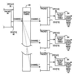
so Fig. 3 is a block diagram that depicts the preferred system for
identifying output ports and forwarding packets in a multiport switch. The
block diagram shows a packet 44, on the input side of a 64X64 port switch
having an 8X8 channel switch fabric 40 similar to the switch architecture of
Fig. 1. The packet is incoming to the switch fabric on channel 0 from IPP 0
3s (not shown). The packet is to be multicast via output ports that are
related to
output channels 0, 1, and 7, where output channels 0, 1, and 7 are connected
to respective 4PPs 0, 1, and 7 (not shown).
CA 02329015 2000-10-16
WO 99/55032 -6- PCT/US99/08372
One difference between the system of Fig. 3 and the system of
Fig. 2 is that the headers attached to the packets on either side of the
switch
fabric include two portions. The first portion of each header is an output
channel vector (OCV) 48 that identifies which output channel or output
s channels should receive the packet. Since there are eight output channels,
the output channel vector is an 8-bit vector with one bit uniquely correspond-
ing to each different output channel. The second portion of each header is an
output port index (OPI) 50 that is used as an indicator to determine which
output ports should receive the packet. In the preferred embodiment, the
~o output port index is a 15-bit vector, but the exact number of bits in the
vector
is not critical to the invention.
Another difference between the system of Fig. 3 and the system
of Fig. 2 is that there is an output port table 54 associated with each output
channel. The eight output port tables keep an indexed list of 8-bit output
~5 vectors that represent output port combinations for packet transfers
through
the switch. The output vectors from the eight output port tables combine to
create a 64-bit output vector. At the output side of the switch fabric 40, the
output port index 50 is used to look-up the desired 8-bit output vectors in
the
indexed output port tables. The looked-up output vectors identify which
2o output ports are to receive the switched packet and 8-bit local output port
masks 58 are generated to direct packet delivery to each identified output
port.
Since the output port index is fifteen bits, it can support 2'S, or
32,768, different output vector and corresponding output port combinations.
25 The different output port combinations are identified and packets are for-
warded utilizing a combined vector that is twenty-three bits (eight bits from
the
OCV and fifteen bits from the OPI), as opposed to the prior art which requires
a 64-bit output vector to identify the same number output port combinations
and to forward packets.
3o Fig. 4 is an expanded view block diagram of the preferred
architecture for identifying ports and forwarding packets in accordance with
the invention. The diagram shows only one out of eight channels and eight
out of sixty-four output ports of a 64x64 port switch. The first element in
the
architecture is the input packet processor 64, IPP 0. In the 64x64 switch, the
35 IPP receives packets from eight input ports (not shown), buffers the
packets
to accommodate for fluctuations in traffic, and directs packets to the switch
fabric 70. The elements of importance for the IPP are the output channel
vector generator unit 66 and the output port index generator unit 68. The
CA 02329015 2000-10-16
WO 99/55032 -7- PCT/US99/08372
output channel vector generator unit utilizes header information from an
incoming packet to generate an output channel vector that defines which
output channels will receive the incoming packet. In networks utilizing
Internet protocol (IP), source and destination information is used to generate
the output channel vector. The output channel vector preferably has a width
equal to the number of output channels in the switch, such that in the 8
channel preferred embodiment, the output channel vector is eight bits. Bits
that are set to "1" identify channels that will receive a forwarded packet.
The output port index generator unit 68 also utilizes header
~o information to generate a single output port index that allows an output
port
vector to be "looked-up" in a table. In networks utilizing IP, source and
destination information is used to generate the output port index. In the pre-
ferred embodiment, the output port index is a 15-bit vector. A 15-bit vector
allows for 2'S or 32,768 different output port index combinations and conse-
~5 quently enables the unique identification of 32,768 different 64-bit output
vectors, where each output vector is identified by a unique index. Although
in the preferred embodiment the output port index is fifteen bits, the exact
width of the output port index is not critical to the invention. It should be
noted
that the same output port index is forwarded to all target OPPs and overhead
2o savings are realized by limiting the width of the output port index to less
than
the total number of output ports in the switch.
Referring again to Fig. 4, the switch fabric 70 of the preferred
embodiment is a conventional 8x8 physical switch that provides the paths for
packet transfers. Although an 8X8 switch fabric is described, the exact
25 number of channels is not critical to the invention. An exemplary
alternative
switch fabric has sixteen input channels and sixteen output channels.
The output packet processor 72, OPP 0, receives packets from
the switch fabric 70 and is responsible for buffering and distributing the
packets to the attached output ports 80. The elements of importance within
3o the OPPs are the output port table 74, the output port table look-up unit
76,
and the output port vector processor unit 78. The output port table, briefly
described above, is an indexed table of output port vectors. The width of
each output port vector stored within the output port table is preferably
equal
to the number of output ports connected to the OPP. For example, in the
35 case where eight output ports are connected to the OPP, the output port
vector is eight bits, or one byte. The number of output port vectors stored
within the output port table can vary, but preferably the number of output
port
vectors stored in the output port table does not exceed the number of unique
CA 02329015 2000-10-16
WO 99/55032 -$- PCT/US99/08372
vector combinations that can be generated by the 15-bit output port index.
If the number of output port vectors does not exceed the number of unique
vector combinations of the output port index, then each output port vector can
have a unique output port index. For example, in the preferred 64x64 switch,
the 15-bit output port index allows 32,768 vector combinations and, therefore,
the maximum number of 1-byte output port vectors stored in each output port
table should not exceed 32,768.
Although the output port table 74 is depicted in Fig. 4 as a
stand-alone table, the output port table can be thought of as a continuous
table that includes a bit for all of the output ports in the switch. Referring
to
Fig. 5, the combined output port table 84 (output port tables 0 through 7, OPT
0-OPT 7) is depicted as a single continuous table with register locations for
output ports 0 through 63. Each 64-bit output port vector has a unique 15-bit
output port index represented for description purposes at the top of the table
~5 as an arabic number, such as the numbers 1 through M. With a 15-bit exit
port index, M is equal to 32,768.
An important feature of the output port tables 74 and 84 is that
the output port table is dynamic. The output port table can be programmed to
add output port vectors to the table based on, for example, time of use or
2o frequency of use, and the output port table can be modified based upon
information from the input side of the switch or the output side of the
switch.
One exemplary way of maintaining the output port table is to add output port
vectors to the table based upon a history of the output port combinations
requested by actual packets passing through the switch. New output port
2s combinations are added to the output port table until the output port table
reaches the maximum number of output port vectors. Once the output port
table has stored the maximum number of output port vectors, the oldest
output port vectors are replaced whenever a new output port combination is
utilized by a packet. Alternatively, the output port vectors may be maintained
3o by frequency of usage, where the output port vectors that are used most
frequently are maintained in the output port table and the output port vectors
that are used least frequently are replaced by more frequently utilized
vectors.
Referring back to Fig. 4, the next element in the architecture
3s is the output port table look-up unit 76. The output port table look-up
unit
performs the function of obtaining the output port index from a packet and
utilizing the output port index to look-up the related output port vector in
the
output port table 74. The advantage of using an output port index to identify
CA 02329015 2000-10-16
WO 99/55032 -9- PCT/US99/08372
an output port vector is that an entire output port vector, for example a 64-
bit
output port vector, can be identified by forwarding only one 15-bit vector
through the switch fabric 70. An example of the look-up process is depicted
in Fig. 5. Vllhen the output port index identifies, for example, the index
number "1," highlighted by the pointer, the entire 64-bit output port vector
stored in the same column of the combined output port table is accessed.
The 64-bit output port vector has set bits related to each output port 88 that
is
to receive a packet. In a unicast only one bit will be set, whereas in a
multicast multiple bits will be set.
The next element in the preferred architecture is the output port
vector processor unit 78. The output port vector processor unit is responsible
for utilizing the output port vector that is accessed from the output port
table
74 to forward packets to the appropriate output ports 80. For example,
referring to Fig. 5, if the output port vector with index number "1" has bits
set
~ 5 for output ports 1, 3, 6, 15, and 56, then the respective output port
vector
processor units 78 will generate respective local output port masks. The
output port vector processor units will replicate the outgoing packet, where
multicasts are required, and forward the packets to output ports 1, 3, 6, 15,
and 56. The output port vector processor units manage packet forwarding
20 only for packets in their respective switch channels.
Although in the preferred architecture the different function-
specific units are described as being physically located within the IPPs and
OPPs, the different function-specific units can have other physical locations
and still perform the same function.
25 A method for forwarding packets to target output ports in a
switch having multiple output ports is described with reference to Fig. 6. The
first step 100 in the method involves receiving a packet at an input,
preferably
an IPP 64 equipped with an output channel vector generator unit 66 and an
output port index generator unit 68. The next step 102 involves the IPP
3o determining to which outputs the packet will be forwarded. After the target
outputs are determined, in step 104, an indicator is attached to the packet
that enables subsequent identification of the output vector, which specifies
the target output ports for receiving the packet. In the preferred embodiment,
step 104 involves attaching an 8-bit output channel vector and a 15-bit output
35 port index to the packet. In step 106, the packet and the attached
indicator
are passed through the switch fabric. In step 108, the indicator attached to
the packet is utilized to identify the output vector for the packet. In a
preferred
embodiment, the 15-bit output port index is utilized to look-up the output
CA 02329015 2000-10-16
WO 99/55032 -10- PCT/US99/08372
vector in a table. Typically, the output port index and the packet have
completely passed through the switch fabric and into an OPP before step 108
begins, although step 108 can begin as soon as the output port index passes
through the switch fabric, but before completion of the passage of the payload
portion of the packet. In a last step 110, the packet is forwarded to the
outputs that are identified by the output vector. Optionally, the output
vector
obtained from the look-up table is attached to each forwarded packet to
enable further routing.
In accordance with the invention, additional bandwidth savings
are realized when the number of ports on a multiport switch is increased.
Since a single index is used to represent all output port combinations, a
switch can be scaled up without needing to change the size of the output port
index. For example, Fig. 7 depicts a 256 input port 118 by 256 output port
switch 130 having sixteen input packet processors 120, a switch fabric 124,
~5 and sixteen output packet processors 128. In accordance with the prior art,
a 256-bit output vector would be assigned to each packet incoming to one of
the sixteen IPPs. The 256-bit vector would then be forwarded through the
switch fabric with each packet that is forwarded through the switch fabric,
thereby adding a significant volume of traffic through the switch fabric. In
2o contrast, in a 256X256 port switch utilizing the output port identification
method in accordance with the invention, a 31-bit output vector consisting of
a
16-bit output channel vector and 15-bit output port index or indicator is
utilized
to accomplish the same result.
The architectural changes required in accordance with the
2s invention to accommodate the addition of new output ports onto an existing
switch consists of adding fields to the output port table while maintaining
the
size of the output port index constant. Referring back to Figs. 4 and 5, if
new
output ports 64 through 255 are added to the 64 output port switch to create
the 256-port switch in Fig. 7, new fields are added to the combined output
3o port table 84 such that the new combined output port table is 256 bits
wide,
but the same 15-bit output port index is still able to identify 32,768 output
port
vectors. In contrast, a prior art switch would require that the output vector
passing through the switch fabric be changed from 64-bits to 256-bits.
In an alternative embodiment of the invention, the output port
35 index technique can be used to perform other operations in a similar man-
ner with similar flexibility and overhead savings. For example, filtering of
multicasts at the output side of the switch can be accomplished using a
CA 02329015 2000-10-16
WO 99/55032 -11- PCT/US99/08372
supplemental index and a supplemental look-up table that contains output-
specific information.
In another alternative embodiment of the invention, when a
multicast packet is being sent to output ports that are communicating with
devices that use different communications protocols, packet headers must be
modified to conform to the respective protocols. Supplemental indexed
look-up tables can be used to identify which communications protocols must
be supported. Referring to Fig. 8, the OPP uses a supplemental look-up table
to identify port-specific headers 150 and then sends each individual port-
1o specific header to its respective output port. The payload 162 portion of
the
packet is then sent to the respective output ports simultaneously.
20
30