Note: Descriptions are shown in the official language in which they were submitted.
CA 02329123 2000-10-19
26-06-2000 .=, == a US 009908602
. == !!
SUBSTITWT~:SHBET:; =, ; ; :.. = = = =
a = ~ i = ~ . : ~ = ~ = ~ i i
_= ~ = i ~ ~ ~ ~ ! ~ ~ ~ =
=1 = ==== ~~ !~ == =~ ==
APPARATUS FOR
DISPENSING OF BULK PRODUCT
FIELD OF THE INVENTION
This present invention relates to food dispensing
machines such as those found in bulk food stores or candy
shops. In particular, the present invention relates to an
improved racking, storage, and delivery system of simple,
modular construction, that is suitable for operation with a
wide variety of candies and other products including
hardware such as nuts and low aspect ratio screws or bolts.
BACKGROUND OF THE INVENTION
Food dispensing machines have long been known.
They range from coin operated devices, such as bubble gum
machines, simple open topped bins and screw conveyor devices
as shown in U.S. Patent 4,790,457, that are commonly found
in bulk food stores. These bulk food bins are often prone
to contamination. A scoop is usually provided in these
existing systems to allow customers to scoop out a desired
quantity of product. The handling of food products in this
way makes bulk foods a ready ground for undesired
contamination. The containers themselves may not be cleaned
very frequently.
- Existing bulk food bins are also cumbersome to
use. Most often, the units 'require the user to hold open a
lid or-door while scooping out product form the storage
area, only to have the lid shut closed while the user
empties the contents of the scoop into a bag or other
container. Bulk vending systems in which the lid remains in
AMENDED SHEET
CA 02329123 2006-06-20
2
an open position create another problem -- often the
consumer forgets to close the lid when he or she is finished
scooping out product. This enables dust, dirt and vermin
access to the contents of the dispenser creating a
contaminated environment.
Product may also be wasted by the consumer
resulting in the loss of profitability to the merchant as
the consumer may often drop product on the floor due to
overfilling or mishandling of the scoop.
Conventional rack systems for bulk dispensers for
displaying and dispensing candy and the like are usually
made in the form of a solid shelved structures, and
sometimes include locking drawer devices in conjunction with
the shelves as shown in U.S. patent 5,445,294. Often, such
structures are placed on a table top or counter top. These
structures occupy a relatively large amount of space which
leaves a relatively limited area for placement of the
dispensing units. Also, due to the limited open area that a
conventional solid rack system provides, the candy within
the containers cannot be scene very well by consumers,
especially when the amount of candy left in the dispenser is
low, and thus, the display function oi the rack system is
reduced.
Finally, dispensers on existing rack systems are
awkward to refill. Usually a merchant must remove each
individual dispenser from the rack to refill it on a table
or on the floor. Additionally, a merchant must have a
designated area to warehouse product refills.
CA 02329123 2006-06-20
2a
There remains a need for a simple, bulk food
dispensing apparatus and rack system that is easy to clean,
not easily prone to contamination, easily refillable, and
allows a user to easily dispense any amount of product so
desired.
SUMMARY OF THE INVENTION
It is an object of the present invention to
provide a rack system for holding a plurality of dispensing
units for displaying and dispensing candy and the like
therefrom.
CA 02329123 2000-10-19
WO 99/53808 PCT/US99/08602
- 3 -
It is another object of the present invention to
provide a rack system for holding a plurality of dispensing
units that can be easily refilled and maintained.
It is still a further object of the present
invention to provide a bulk vending system in which food
product is dispensed in a hygienic manner.
It is still another object of the present
invention to provide a bulk vending system for allowing a
consumer to easily dispense product.
It is yet another object of the present invention
to provide a bulk vending system which virtually eliminates
wasted product due to consumer mishandling.
A still another object of the present invention is
to provide a bulk vending system for displaying and
dispensing a plurality of bulk dispensers in a minimum
amount of floor space.
In one aspect of the present invention, a bulk
vending apparatus for dispensing a user-determined amount of
product stored in bulk is provided that includes a rack unit
having a plurality of support structures capable of
extending out from the rack unit and a plurality of
dispensing units each containing a product for dispensing.
The dispensing units are arranged on each of the support
structures. Finally, the rack unit also includes a
restraining means to restrain all but a first support
structure of the plurality of support structures when a
first support structure is extended from the rack unit.
In another aspect of the present invention, a
vending apparatus for dispensing a user-determined amount of
product stored in bulk is provided which includes a storage
portion for storing loose product, and a dispensing barrel
located at the bottom of the storage portion. The
CA 02329123 2000-10-19
WO 99/53808 PCT/US99/08602
- 4 -
dispensing barrel includes a product inlet and outlet.
Finally the bulk vending apparatus also includes an auger
having a major diameter located within the dispensing
barrel, and a brush member for brushing away excess product
from the major diameter. The auger is rotatable to dispense
a metered quantity of the product.
These and other features, aspects, and advantages
of the present invention will become much more apparent by
reference to the following detailed description and the
accompanying drawings.
BRIEF DESCRIPTION OF THE DRAWINGS
Fig. 1 is a front perspective view of a rack
system according to the present invention, on which a
plurality of candy dispensers are mounted.
Fig. 2 is a rear sectional perspective view of a
rack system illustrating a restraining system according to
the present invention.
Fig. 3 is a side sectional view of a rack system
illustrating a restraining system according to the present
invention.
Fig. 4 is a perspective view of a candy dispenser
unit according to the present invention.
Fig. 5 is an exploded view of a dispenser portion
for a candy dispenser according to the present invention.
Fig. 6 is a sectional view of a dispenser portion
of a candy dispenser according to the present invention.
Fig. 7 is a sectional view of a refill opening and
door for a candy dispenser according to the present
invention.
CA 02329123 2006-06-20
- 5 -
Fig. 8 is a rear view of a dispenser porzion -Fcr
a candy dispenser accerding to the present invention.
Fig. 9 is a sectional view of a dispenser portion
illustrating a baffle member for a candv dispenser accoYd'_r.g
to the present invention.
Fig. 10 is a sectional view of a middle portion of
a dispenser portion for a candy dispenser according to the
present invention.
Fig. 11 is a sectional view of a spout member of
a dispenser portion for a candy dispenser according to the
present invention.
Fig. 12 is a sectional view of a front porticn off
a dispenser portion of a candy dispenser illustrating a
ratchet mechanism according to the present invention.
Fig. 13 is a top view of a locking knob for the
dispenser portion of the present invention.
DESCRiPTION OF THE PREFERRED EMBODIMENTS
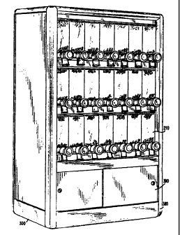
Referring to Figs. 1-3, a structurally sound rack
system 300 is shown having a framework 320, a plurality c=
bulk product dispensers 310, and a facade 380. Tre
framework 320 supports shelving support members (trays) 330,
332 and 334 for supporting the bulk product dispensers 310,
and a storage area 390 having doors (sliding, swinging, or
in the alternative removable covers). Although
the current embodiment of the present inventiwn contains
three shelving support members in a horizontal positior_,
rack system according to the present invention may inc=ude
any number of shelving support members in vertical positions
also.
The framework 320, shelving support members, and
facade 380 can be made from any one of a number of di f feren-_
CA 02329123 2000-10-19
WO 99/53808 PCT/US99/08602
- 6 -
materials including wood, plastic, steel, or combination
thereof. The framework and shelving members are designed to
be structurally rigid for their intended function.
Anchored to the framework 320 and to each shelving
support member are shelving slides 370, which provide
extension capability to each shelving support member. These
slides enable a shelving support member to be pulled
forward, away from the rack unit. In addition, the rack
system includes a novel restraining system that allows only
a single shelving unit at a time to be extended out from the
rack system.
The restraining system includes three cables, 360,
361 and 362, whose ends are attached to the rear of each
shelving support member. Each cable connects one shelf
member with another as well as anchoring the shelves to the
racking system. As shown in Figures 2 and 3, cable 360
connects shelving unit 332 with 334, passing through rear
wall anchors 350 and 351; cable 361 connects shelving unit
330 with 332, passing through rear wall anchors 352 and 353;
and finally, cable 362 connects shelving support member 330
with 334, and passes through rear wall anchors 350, 351, 352
and 353.
The cables may be made of steel, or an equivalent
material having similar material properties. The diameter
of the steel cables is determined by the cable material and
the tensile load required for a cable based on the force
necessary to move, and restrain the shelving support
members.
The anchors located on the rear wall of the
racking system may be an eye type anchor, or any type of
anchor that allows a cable to be threaded through therein.
Whereas the anchors affixed to the rear of each shelving
support members can be any type of anchor which allows an
end of a cable to be affixed thereon. These anchors can
CA 02329123 2000-10-19
WO 99/53808 PCT/US99/08602
- 7 -
include hook and eye anchors, in which case the end of the
cables must have a means of attachment thereto. Such means
can include clips, hooks, and the like. As an alternative,
the ends of the cable can be attached to the shelving unit
anchors by welding or adhesive.
Each cable is made to a predetermined length,
which allows only one shelving support member to be opened
at a time. Thus, when all the shelving support members are
in the closed position, cables 360, 361 and 362 have slack,
which hangs freely within the backside of the rack system.
However, when shelving support member 334 is in an open
position, for example (i.e., is pulled out away from the
rack unit 300 (and away from the back wall 310; see Fig. 3),
the slack in cables 360 and 362 is taken up and the cables
are placed under tension (i.e., being extended to their full
predetermined length).
The length of the cables allow the shelving
support member 334 to be pulled out up to a specific
distance. This distance is preferably approximately equal
to the width of the shelving support member, although the
ultimate length of cables 360 and 362 can be designed to
handle any distance that may be required to access the bulk
dispensing units for refilling or maintenance.
When cables 360 and 362 are under tension, as a
result of shelving support member 334 being pulled out, the
remaining shelving support members 330 and 332 remain locked
in place due to the tension in cables 360 and 362. The
restraining system works similarly when either shelving
support member 330 or 332 is open.
The purpose behind this system is to provide an
easy and effective manner to refill the bulk dispensing
units 310 as well as to ensure that the rack unit 300 will
not tip over in the event of having too many shelving
members in the open position. Accordingly, the rack unit
CA 02329123 2000-10-19
WO 99/53808 PCT/US99/08602
- $ -
300 is designed so that the unit will remain stable in all
conditions of operation.
For example, in a worst case scenario when, say,
the bulk dispensing units 310 arranged on the upper most
shelving member 334 are full, and the remainder of the bulk
dispensing units 210 arranged on the other shelving support
members are empty, and shelving member 334 is placed in the
open position, the unit will not topple forward, even with
additional weight from a merchant leaning on the shelving
support member 334 when refilling the upper units.
When an open shelving support member is returned
into the rack unit 300, then another of the shelving members
may be opened, albeit, only one at a time.
Although the present invention includes the
currently described novel restraining system, this does not
limit the invention to this restraining system. Other
restraining systems familiar to one skilled in the art may
also be used. Such systems may include similar systems
using elastic cords and springs, or a series locking levers
that keep remaining shelving support members locked in a
closed position when one of the shelving support members is
open. In addition, electrical means and methods for
ensuring that only a single draw is open are not beyond the
scope of the present invention.
Figs. 4-12 illustrate a type of bulk dispensing
unit 210 that may be used with rack system 300.
Specifically, Fig. 4 shows a perspective view of bulk
dispenser 210 illustrating overall housing 219. The housing
219 may be made from any number of materials including wood
or steel, but preferably plastic, and may be manufactured as
a single molded product, or multiple piece assembly.
The bulk dispenser unit also includes refill
opening 225 having a refill door 230. The sides of the bulk
CA 02329123 2006-06-20
- 9 -
disper.ser housing 219 ir.clude notched areas 215 ar.: 2=
which providz an area for receiving a she=ving suppo:-t
member, so that the disper.ser ur.it 210 mav be loc:ced inco
the shelving support member for stable operation.
As shown in Fig. 4, the front wa: l 214 of the
dispenser unit 210 is preferably comprised of a transparen_
material. This allows one to view the material contents oi
the dispenser unit 210, without having to open refill doc=
230 and peer into the dispenser unit 210 through refill
opening 225. in addition, as shown in Figs. 6 and 7, an
internal wall located behind the existing front wall 214 c_
the housing 219 creates an internal space 213 for containing
loose product. This creates a display "window" giving an
"always full" view for the bulk dispensing unit 310
iliustrating the product for dispensing.
Finally, the dispenser unit 210 includes
dispensing barrel assembly 200 which dispenses the loose
product contained within the housing 219 to the consumer.
As shown in Figs. 5 and 6, the dispensing barrel assembly
200 includes dispensing tube 133, having a product receiving
area 135 for receiving product from the product stored in
the housing 219. In the front of dispensing barrel assembly
200 is a barrel cap 90, which includes the front half of a
spout 130. The back half of spout 130 is =ntegral with
dispensing barrel 133.
The main component included within the dispensin=
barrel assembly 200 is an auger 7-00, which is comprised of
a plurality of individual flights 102 which are centrally
assembled side by side over a shaft 110, through a central
opening in each flight 102. The central opening in eac::
flight is designed to conform zo the shape of the shart 11_0,
so as to be radially locked or.to the shaft 110. As shown =n
Fig. 5, the shaft 110 is in :.he form of a square, but can be
of any shape. In addition, t he auger, or auger and sha=:
may be manufactured as a single one-piece unit.
CA 02329123 2000-10-19
WO 99/53808 PCT/US99/08602
- 10 -
The auger may be exchanged with another auger-
shaft assembly having a different pitch, major diameter,
minor diameter, and pitch diameter of the flights. This may
be done in order to compensate for different size product to
be dispensed. These dimensions are limited, however, by the
overall diameter of the dispensing barrel 133 and spout
diameter. Preferably, the size of the flights for the
present invention will be of a size for accepting a wide
variety of small loose product including candy, nuts, coffee
beans and the like.
At the product exit end of the auger 100 is an end
cap 101 that slides over the end of shaft 110, terminating
the flights 102. At the opposite end is a rear bushing 120,
which is received by an opening 137 in the rear of the
dispensing barrel 130, in the back wall adjacent the product
receiving area 135.
The dispenser barrel 133 is capped by barrel cap
90. Immediately adjacent and located within the barrel cap
90 is a ratchet gear 70 and a ratchet spring 80. The
ratchet gear 70 slides over the center shaft 110 through a
conforming center portion. The ratchet allows one-way only
rotation of the auger within the dispensing barrel 130. it
is noted that the one-way rotation of auger 100 can also be
accomplished in any number of ways including both electrical
and other mechanical means.
A cap cover 60, also with central portion
conforming to the shape of shaft 110, covers the ratcheting
mechanism. A knob 35 including rear portion 50 and front
portion 40, slides over the end of shaft 110. The knob
portion is then completed with color or product designating
chip 20, inserted within front knob portion 40, and sealed
with transparent cover 10 to allow a consumer to view a
specific characteristic (color, name, shape, size) of the
product contained within the bulk dispensing unit.
CA 02329123 2000-10-19
WO 99/53808 PCT/US99/08602
- 11 -
The entire dispensing barrel assembly 200 is held
together by front and rear fasteners. At the rear of
dispensing barrel 130, a machine screw 150 locks a locking
bushing 160 and rear bushing 120 onto the center of the rear
end of shaft 110. As shown in Fig. 13, the central portion
of locking knob 170, having an equivalent shape of locking
bushing 160, also contains an inner hub 171 and a post 172.
When the locking knob 170 is slid over the locking bushing
160, a clockwise twist of the locking knob 170 moves an end
of locking bushing 160 up the inner hub 171 terminating the
end at post 172.
A front machine screw 30 locks the knob halves 40
and 50, the ratchet gear 70, the ratchet spring 80 and
barrel cap 90 into the front end of the shaft 110. The
front machine screw is hidden from view by product
designating chip 20 and transparent cover 10.
The completed dispensing barrel 200 is then slid
into the lower portion of the housing 210. There it is
secured in place by a tab 142 and secured by a set screw
140, threaded into sonic insert 146.
Finally, a brush assembly 175 including a brush
190 secured to a brush holder 180, is located within the
dispensing area of the lower portion of the housing 219
directly above the product receiving area 135. The brush
assembly insures that the material to be dispensed does not
jam the auger at the front edge of the product receiving
area 135, by "brushing" excess product away from the
intersection of the auger and product receiving area 135.
The excess material brushed away is swept back into the
preceding flight.
The operation of the dispenser unit 210 is as
follows. As shown in Fig. 6, product 5 fills the storage
area of the housing 219, and is funneled down into the
product receiving area 132 of dispensing barrel 130 by a
CA 02329123 2000-10-19
WO 99/53808 PCT/US99/08602
- 12 -
sloped floor 7 and the brush assembly 175. As a consumer
turns knob 35 clockwise, the auger 100 also rotates
clockwise. The primary function of the rachet assembly is
to keep the auger from rotating in the opposite direction,
i.e., counter clockwise. In addition, the speed of the
auger can be limited somewhat by the pressure of the ratchet
spring 80 on the ratchet gear 70. This creates a "clicking"
sound as one rotates the handle.
Due to gravity, product 5 fills the voids in each
of the exposed individual flight of auger 100. The product
5 is carried down the auger 100 by the clockwise rotation of
knob 35. As the product 5 passes the individual flights
located directly below brush 190, excess product located
above the top part of the screw thread is brushed back to be
funneled into the preceding flights of auger 100 located
toward the rear of the product receiving area 135.
Product is moved along the length of auger 100
where it exits the dispensing barrel at the flights 102
located above exit spout 130.
The assembly allows the user to obtain as much or
as little product as desired by rotating the auger a large
or small amount, respectively. In addition, the speed of
the product exiting the dispensing barrel 200, although
somewhat limited by the ratcheting mechanism, can be user-
determined by rotating the knob 35 in a fast or slow
fashion.
When the amount of product has been exhausted in
the storage area of the dispensing unit housing 219, the
unit may be refilled with more product. However, prior to
refilling, the dispensing barrel may be removed for cleaning
and maintenance by removing retaining screw 140 and tab 142
and sliding the unit out from the base of the housing.
CA 02329123 2000-10-19
WO 99/53808 PCTIUS99/08602
- 13 -
When no more product appears after repeated
rotations of the knob 35, the unit requires refilling. As
shown in Figs. 3 and 7, the storage area of the dispensing
unit 210 is refilled by sliding the appropriate shelving
support member to the open position, and lifting lid 230 to
expose the opening 225 located above the storage area. The
merchant can then place product into the storage area
through the opening 225, and, depending upon the popularity
of the product, fill the storage area to a desired level.
The lid 230 is then closed or replaced and the shelving
support member returned to the closed position.