Note: Descriptions are shown in the official language in which they were submitted.
CA 02329201 2000-12-20
TITLE OF THE INVENTION:
EXTERNAL WALL CONSTRUCTION
BACKGROUND ~lE' THE INVENTION
Field of the Invention:
The present invention relates to an external wall
construction comprising a bearing wall constituted by fixing
a plurality of ceramic type external wall panels to a building
framework of a building through framework wall construction
methods or skeleton framing wall construction methods.
Description of the Related Arts
Conventional external wall constructions for building
structural panels are known to be external wall constructions
that are constructed through framework wall construction
methods or skeleton framing wall construction methods.
An example of such a conventional external wall
construction 9 is illustrated in Fig. 19.
This external wall construction 9 includes a building
framework 92 constituted of framing materials 921 such as
squared logs, building structural panels 93 fixed on the
building framework 92, waterproof sheets 94 set on the building
structural panel 93, lateral furring strips 95 fixed on the
building structural panels 93 with the waterproof sheets 94,
and external wall panels 96 for example ceramic type panels
fixed on the building structural panels 93 with the lateral
furring strips 95 (see Figs. 19 and 20).
The building structural panels 93 are unified with the
building framework 92 to form a bearing wall 930 which resist
1
CA 02329201 2000-12-20
the vertical or horizontal pressure, and thus a security of
constructional bearing strength is secured.
The constructing process of this external wall
construction 9 includes framing the building framework 92 with
the framing materials 921 in the first step, fixing the building
panels 93 by face-nailing nails 935 on the building framework
92 in the second step (As a result, bearing wall 930 is formed. ) ,
fixing lateral furring strips 95 on the building structural
panels 93 interposing the waterproof sheets 94 by nailing in
the third step, and fixing the external wall panels 96 for
example ceramic type panels on the building structural panels
93 interposing the lateral furring strips 95 by nailing in the
fourth step.
A coating material is applied to a front surface of the
external wall panels 96 as necessary.
In this manner, the external wall construction 9 can be
obtained.
However, such a conventional external wall construction
9 presents following drawbacks.
The aforementioned external wall construction 9 has many
components i. e. the building framework 92, the building
structural panels 93, the waterproof sheets 94, the lateral
furring strips 95, and the external wall panels 96.
Consequently the construction is extremely complicated (see
Figs. 19 and 20).
And the complicated construction causes requirements of
many construction steps and also leads to increased material
costs.
And the aforementioned external wall construction 9
except for the building framework portion is so thick that
2
CA 02329201 2000-12-20
effective indoor spaces are reduced.
It would be thinkable to fix the external wall panels
96 directly to the building framework 92 through face-nailing
with the furring strips 95 being interposed therebetween.
However, in case the external wall panel is ceramic type, cracks
966 or chippings 967 are apt to be generated through face-
nailing in peripheries of portions at which nails 935 pierce
through rearward surfaces 961 of the panels as illustrated in
Fig. 21 since the external wall panels 96 do not exhibit
particular shock-resistant characteristics. Consequently,
fixing force of the external wall panels 96 to the building
framework 92 will be degraded and may cause leakage of water.
While it is possible to prevent penetration of water into
the interior of the building (arrow B in Fig. 20) by the
provision of the waterproof sheets 94 in the external wall
construction 9, absorption of water of the external wall panels
96 themselves from their rearward surfaces 961 cannot be
prevented.
So, generally, the rearward surfaces 961 of the external
wall panel 96 is coated by sealer, but the treatment is still
insufficient to prevent absorption of water. As a result
absorption of water may occur particularly through the cracks
966 or chippings 967. Such absorption of water may cause
dimensional changes in the external wall panels 96. Moreover,
if carbon dioxide penetrates through portions of the cracks
966 or chippings 967, carbonation or neutralization of external
wall panels 96 through aging may be promoted and may lead to
deterioration in durability.
There is a drawback that preventing condensation on
indoor surfaces of the external wall panels 96 or building
3
CA 02329201 2000-12-20
framework 92 may become difficult when the external wall panels
96 is directly fixed to the building framework 92.
More particularly, when the external wall panels 96 is
directly fixed to the building framework 92 as illustrated in
Fig. 24(A), heat insulators 98 are formed on indoor sides of
the external wall panels 96. Particularly during wintertime,
air 7 of high temperature and humidity residing indoors passes
through the heat insulators 98 and reaches the interior of the
external wall panels 96. The temperature of the proximity to
the external wall panels 96 is low during wintertime, since
it is close to outside-air temperature. Thus, the air 7 of high
temperature and humidity passing from indoors through the heat
insulators 98 is cooled to result in condensation on inner
surfaces of the external wall panels 96, the heat insulators
98, and the surface of the building framework 92.
In an arrangement in which the building structural panels
93 are fixed to the building framework 92 and in which the
external wall panels 96 are constructed with the lateral furring
strips 95 being interposed therebetween as illustrated in Fig.
20, it is possible to provide ventilation layers 97 between
the building structural panels 93 and the external wall panels
96 (see Fig. 23).
More particularly, the ventilation layers 97 are provided
in the following manner. When the external wall panels 96 is
constructed through horizontal siding work, the vertical
furring strips 950 are constructed in longitudinal directions
as illustrated in Fig. 22 (A) , and when the external wall panels
96 is constructed through vertical siding work, the lateral
furring strips 95 are formed on notches 951 and are constructed
in vertical directions as illustrated in Fig. 22(B).
4
CA 02329201 2000-12-20
With this arrangement, it is possible to obtain
ventilation layers 97 wherein air 7 residing between the
external wall panels 96 and the building structural panels 93
is reliably released upward. Generation of condensation as
explained above can be accordingly prevented since air 7 passes
through the ventilation layer 97 as illustrated in Fig. 23.
Note that reference numeral 928 in Figs . 22 (A) , 22 (B) denotes
a window frame.
However, the ventilation layer 97 cannot be provided in
case the external wall panels 96 are directly fixed to the
building framework 92 (see Fig. 24(A)). Since girths 924 of
the building framework 92 intercept spaces formed between right
and left continuous columns 923 as illustrated in Fig. 24 (B) ,
the passage of air 7 of high temperature and humidity for upward
release is blocked thereby (see Fig. 24(A)).
Condensation may be accordingly generated on the external
wall panels 96, heat insulators 98 or the building framework
92, which may lead to degradations of durability of the bearing
wall owing to corrosion of the building framework 92 or
degradations of heat-insulating performance owing to swelling
of the heat insulators 98. Penetration of moisture into the
interior of the external wall panels 96 will cause gradual
degradation of the durability of the panels themselves, and
may also cause corrosion of timbers in case the building
framework is comprised of timbers.
SUMMARY OF THE INVENTION
The present invention has been made in view of the above
problems of the related art, and it is an object of the invention
to provide an external wall construction improving workability,
CA 02329201 2000-12-20
waterproof properties, durability and ventilating properties
of a bearing wall.
The present invention relates to an external wall
construction comprising a building framework of a building and
a bearing wall constituted with a plurality of ceramic type
external wall panels to be fixed to the building framework,
wherein the external wall panels are formed by backing resin
sheets on rearward surfaces thereof, and wherein waterproof
tapes are interposed between the external wall panels and the
building framework.
As explained above, the external wall construction
comprises the building framework and the plurality of external
wall panels: Thus the external wall construction is simple
arrangement and may be easy to be constructed. Decreases in
material costs can also be achieved due to the small number
v
of constituents.
Further, since the external wall panels are formed by
backing resin sheets on rearward surfaces thereof, water or
carbon dioxide will not be absorbed from the rearward surfaces .
Accordingly, dimensional changes in the external wall panels
can be prevented, and carbonation or neutralization will not
be promoted. It is thereby possible to obtain an external wall
construction having superior durability.
The provision of resin sheets backed to the external wall
panels further serves to prevent generation of cracks or
chippings when the panels is face-nailed to the building
framework.
Waterproof tapes are interposed between the external wall
panels and the building framework. More particularly, the
waterproof tapes are interposed between the resin sheets backed
6
CA 02329201 2000-12-20
on the rearward surfaces of the external wall panels and the
framing materials constituting the building framework.
In this manner, penetration of water from between the
external wall panels and the building framework can be reliably
prevented.
It has also been enabled this arrangement to omit a
separate step for constructing the waterproof sheets as it had
been necessary in conventional structures for constructing
exterior walls, and to thereby achieve further simplification
of the external wall construction, and moreover, further
simplification of construction.
As explained above, it is possible to provide an external
wall construction improving workability, waterproof
properties, durability, and ventilating properties of a
bearing wall.
BRIEF DESCRIPTION OF THE DRAWINGS
A more complete appreciation of the invention and many
of the attendant advantages thereof will be readily obtained
as the same becomes better understood by reference to the
following detailed description when considered in connection
with the accompanying drawings, wherein;
Fig. 1 is a cross-sectional view for explaining the
external wall construction according to Embodiment 1;
Fig. 2 is a front view of the external wall construction
according to Embodiment 1;
Fig. 3 is a longitudinal sectional view for explaining
the external wall construction according to Embodiment 1;
Fig. 4 is an explanatory view of a external wall panel
according to Embodiment 1;
7
CA 02329201 2000-12-20
Fig. 5 is an explanatory view of a covering material
according to Embodiment l;
Fig. 6 is an explanatory view of a external wall panel
according to Embodiment 2;
Fig. 7 is an explanatory view of a external wall panel
according to Embodiment 3;
Fig. 8 is a cross-sectional perspective view of the
external wall construction according to Embodiment 4;
Fig. 9 is a front view of the external wall construction
according to Embodiment 4;
Fig. 10 is a longitudinal sectional view for explaining
the external wall construction according to Embodiment 4;
Fig. 11 is a perspective view of a girth according to
Embodiment 4;
Fig. 12 (A) is a sectional view seen from a direction as
indicated by the arrow from line A-A of Fig.8;
Fig. 12 (B) is a sectional view seen from a direction as
indicated by the arrow from line B-B of Fig.8;
Fig. 13 is an explanatory view of a method for connecting
a continuous column and a girth according to Embodiment 4;
Fig. 14 is a cross-sectional perspective view of the
external wall construction according to Embodiment 5;
Fig. 15 is a sectional view seen from a direction as
indicated by the arrow from line C-C of Fig. 14;
Fig. 16(A) is a top view of a continuous column,
supporting columns and girths according to Embodiment 5;
Fig. 16 (B) is an explanatory view of a building framework;
Fig. 17 is a cross-sectional view of the external wall
construction according to Embodiment 6;
Fig. 18(A) is a top view of a continuous column,
8
CA 02329201 2000-12-20
supporting columns and girths according to Embodiment 6;
Fig. 18 (B) is an explanatory view of a building framework;
Fig. 19 is Explanatory view of a conventional external
wall construction;
Fig. 20 is a sectional view for explaining a conventional
external wall construction;
Fig. 21 is an explanatory view of face-nailing portions
of a conventional external wall panel;
Figs. 22(A) and 22(B) are explanatory views of furring
strips and ventilation layers of a conventional external wall
panel;
Fig. 23 is an explanatory view of ventilation layers of
a conventional external wall panel;
Fig. 24 (A) is a sectional explanatory view for explaining
problems of a conventional external wall construction when
external wall panels are directly fixed to a building framework;
and
Fig. 24(B) is an explanatory view of the building
framework.
DESCRIPTION OF THE PREFERRED EMBODIMENT
Hard chip cemented boards, magnesium carbonate boards,
wood fiber cemented boards, pulp cemented boards and the like
are used as a ceramic type external wall panel.
Examples of the resin sheet are a polyethylene sheet,
afoam polyethylene sheet, a polyethylene terephthalate sheet,
a vinyl chloride sheet or a vinylidene chloride sheet. The
resin sheet may alternatively be sheets made, for example, by
overlaying a foam polyethylene sheet on a polyethylene
terephthalate sheet, overlaying a foam polyethylene sheet on
9
CA 02329201 2000-12-20
a paper nonwoven cloth or a polyethylene terephthalate nonwoven
cloth, or overlaying a polyethylene sheet on a paper nonwoven
cloth or a polyethylene terephthalate nonwoven cloth.
The building framework is constructed of framing
materials, for instance, of timbers or glued timbers.
The resin sheets are backed to the external wall panels
by means of, for instance, adhesion using adhesives, thermal
fusion, or fusing actions using ultrasonic waves or high
frequency waves.
One example of methods for constructing the external wall
construction according to the present invention will now be
explained.
The building framework is assembled using framing
materials. Then, the waterproof tapes are adhered to the
building framework. A plurality of external wall panels are
backed with resin sheets. Thereafter, the plurality of
external wall panels are adhered to the waterproof tapes with
lateral end portions of the panels abutting against each other.
By fixing these panels onto the building framework through
face-nailing, the bearing wall is completed.
Tt is preferable that a thickness of the external wall
panels is in a range of 12 to 25 mm. With this arrangement,
sufficient strength of the external wall construction can be
secured and easy construction can be provided.
If the thickness of the external wall panel is less than
12 mm, it may become necessary to restrict materials that are
used as the external wall panels for securing sufficient
strength thereof . On the other hand, if the thickness exceeds
25 mm, construction thereof may become difficult.
It is preferable that end portions of the external wall
CA 02329201 2000-12-20
panels are disposed on the framing materials constituting the
building framework. With this arrangement, it is possible to
obtain an external wall construction having even more superior
strength.
It is preferable that the waterproof tapes have
elasticity. With this arrangement, penetration of water from
between the external wall panels and the building framework
can be reliably prevented.
It is preferable that the waterproof tapes closely adhere
to the resin sheets backing the external wall panels and the
building framework, respectively. More particularly, the
waterproof tapes closely adhere to the resin sheets that are
backed to the rearward surfaces of the external wall panels
and the framing materials constituting the buildingframework.
With this arrangement, penetration of water from between the
external wall panels and the building framework can be more
reliably prevented.
It is preferable that laterally neighboring external wall
panels constituting the bearing wall form butt portions with
respective lateral end portions abutted each other, and
vertically neighboring external wall panels form shiplapjoint
portions wherein an upper tongue portion formed at a lower end
portion of one panel and a lower tongue portion formed at an
upper end portion of another panel are joined together, and
covering materials, which comprise elastic joint finishing
materials and mesh-like bodies disposed therein, are provided
on front surfaces of the butt portions and the shiplap joint
portions.
With this arrangement, penetration of water from the butt
portions or shiplap joint portions can be reliably prevented
11
CA 02329201 2000-12-20
while it is enabled to secure sufficient strength of the butt
portions and shiplap joint portions. It is further possible
to obtain an external wall construction of superior outward
design with no joint portions of external wall panels standing
out.
It is preferable that a coating material is applied on
the front surface of the bearing wall. With this arrangement,
it is enabled to obtain an external wall construction of
superior outward design. It is also possible to reliably
prevent the external wall panels from absorbing water or carbon
dioxide, and dimensional changes of the external wall panels
and promotion of carbonization or neutralization can be
reliably prevented. Thus, it is possible to obtain an external
wall construction of more superior durability.
Note that the term "front surface of the bearing wall"
denotes a front surface of the bearing wall including also the
surface of the above-described covering materials if any
covering material should be present.
It is preferable that waterproof tapes are interposed
between the rearward surface at peripheral end portions of the
external wall panels and the building framework, and notched
grooves for ventilation purposes are formed on the girths
constituting the building framework and are across surfaces
of the girths vertically at which they contact the external
wall panels.
As explained above, the external wall constructing
structure comprises a building framework and a plurality of
external wall panels. Thus, the external wall constructing
structure is of simple arrangement and may be easily constructed.
Decreases in material costs can also be achieved due to the
12
CA 02329201 2000-12-20
small number of constituents. Further, time required for
construction can be reduced at worksites.
The external wall constructing structure is capable of
increasing effective indoor spaces since thicknesses of that
can be kept small except for the thickness of the building
framework.
Since the external wall panels are backed with resin
sheets on rearward surfaces thereof, water or carbon dioxide
is hardly absorbed through the rearward surfaces. With this
arrangement, no dimensional changes of the external wall panels
will be generated and carbonization and neutralization will
not be promoted. Thus, it is possible to obtain an external
wall construction having superior durability.
The backing of the resin sheets on the external wall
panels will prevent generation of cracks or chippings when these
panels are face-nailed to the building framework.
The waterproof tapes are interposed between the rearward
surface at peripheral end portions of the external wall panels
and the building framework. More particularly, the waterproof
tapes are interposed between the resin sheets backed on the
rearward surfaces of the external wall panels and the building
framework.
With this arrangement, penetration of water from between
the external wall panels and the building framework can be
reliably prevented.
This arrangement further eliminates the necessity of
separately constructing the waterproof sheets as it has been
necessary in conventional external wall constructing
structures, and it can be achieved for further simplification
of the external wall construction and thus for further
13
CA 02329201 2000-12-20
simplification of construction.
The girths of the building framework are formed with
notched grooves for ventilation purposes on surfaces
contacting the external wall panels. It is thereby enabled to
secure ventilation of the interior of the external wall panels .
With this arrangement, it is possible to prevent air of
high temperature and humidity in the interior of a building
from condensing on rearward surfaces of the external wall panels
or peripheries thereof. Thus, corrosion and other damages on
the building framework can be prevented and an exterior wall
construction structure having superior durability can be
obtained.
The notched grooves are formed to face vertical
directions when the girths are assembled as framings of the
building framework. That is, the notched portions are formed
in directions perpendicular to the length direction of the
girths.
Either a single or a plurality of notched grooves may
be formed per each width of a single external wall panel.
Peripheral end portions of the external wall panel
specify regions up to, for instance, approximately 30 mm inward
of four sides in vertical and lateral directions of the external
wall panel. Further, when the external wall panels are
face-nailed as it will be explained hereinafter, nails are
driven into the peripheral end portions at regions inward of
the four sides in vertical and lateral directions by 15 to 30
mm. More preferably, face-nailing is performed at portions
inward of the four sides of the external wall panel by up to
20 mm.
One example of methods for constructing the external wall
14
CA 02329201 2000-12-20
constructing structure of the present invention will now be
explained.
First, the building framework is constructed of timbers
or the like. Then, waterproof tapes are adhered to portions
of the building framework. The portions are where the
peripheral end portions of the rearward surfaces of the external
wall panels abut against the building framework. Then, a
plurality of external wall panels preliminarily backed with
resin sheets are adhered to the waterproof tapes with their
end portions abutted each other. These panels are fixed onto
the building framework through face-nailing to obtain a bearing
wall.
It is preferable that a thickness of the external wall
panels is in a range of 12 to 25 mm. With this arrangement,
sufficient strength of the external wall construction can be
secured and easy construction can be provided.
If the thickness of the external wall panel is less than
12 mm, it may become necessary to restrict materials that are
used as the external wall panels for securing sufficient
strength thereof . On the other hand, if the thickness exceeds
25 mm, construction thereof may become difficult.
It is preferable that rearward surfaces at the peripheral
end portions of the external wall panels are disposed on the
building framework, and that the peripheral end portions are
fixed onto the building framework through face-nailing at
specified pitches. With this arrangement, it is possible to
obtain an external wall construction having even more superior
strength.
It is preferable that the specified pitch is in a range
of 50 to 150 mm. In case the pitch is less than 50 mm, damages
CA 02329201 2000-12-20
of base materials may be caused at peripheries of face-nailing
portions on front and rearward surfaces of the external wall
panels . On the other hand, in case the pitch exceeds 150 mm,
it will become difficult to form the bearing wall.
It is preferable that the waterproof tapes have
elasticity. With this arrangement, penetration of water can
be reliably prevented by reliably closing slight clearances
formed between the external wall panels and the building
framework and closely adhering there.
It is preferable that the waterproof tapes closely adhere
to the resin sheets of the external wall panels and the building
framework, respectively. More particularly, the waterproof
tapes closely adhere to the resin sheets that are backed to
the rearward surfaces of the external wall panels and the
framing materials constituting the building framework,
respectively. With this arrangement, penetration of water
from between the external wall panels and the building framework
can be more reliably prevented.
It is preferable that laterally neighboring external wall
panels constituting the bearing wall form butt portions with
respective lateral end portions being abutted to each other,
and vertically neighboring external wall panels form shiplap
joint portions wherein an upper tongue portion formed at a lower
end portion of one panel and a lower tongue portion formed at
an upper end portion of another panel are joined together, and
covering materials, which comprise elastic joint finishing
materials and mesh-like bodies disposed therein, are provided
on front surfaces of the butt portions and the shiplap joint
portions. With this arrangement, penetration of waterfrom the
butt portions or shiplap joint portions can be reliably
16
CA 02329201 2000-12-20
prevented while it is enabled to secure sufficient strength
of the butt portions and shiplap joint portions. It is further
possible to obtain an external wall construction of superior
outward design with no joint portions of external wall panels
standing out.
Note that the term "front surface of the shiplap joint
portion" denotes a front surface of the external wall panels
at which end portions on the surface side of the panels are
abutted (reference numeral 36 in Fig. 5).
It is preferable that a coating material is applied on
the front surface of the bearing wall. With this arrangement,
it is enabled to obtain an external wall construction of
superior outward design. It is also possible to prevent
reliably the external wall panels from absorbing water or carbon
dioxide, and accordingly dimensional changes of the external
wall panels and promotion of carbonization or neutralization
can be reliably prevented. Thus, it is possible to obtain an
external wall construction of more superior durability.
Note that the term "front surface of the bearing wall"
denotes a front surface of the bearing wall including also the
surface of the above-described covering materials if any
covering material is present.
It is preferable that lateral surfaces of continuous
columns constituting the building framework fix supporting
columns. Therefore, the continuous columns can be reinforced.
Thereby strength of the building framework is secured.
It is preferable that the continuous columns and the
supporting column are of identical sectional dimensions. With
this arrangement, further decreases in construction costs can
be achieved.
17
CA 02329201 2000-12-20
It is preferable that the end portions of the girths are
fixed to upper ends of the supporting columns. More
particularly, the girths may be fixed in conditions in which
their end portions are mounted on upper ends of the supporting
columns . With this arrangement, the girths can be easily and
reliably fixed to the continuous columns through the supporting
columns.
It is preferable that the notched grooves have a depth
of 10 to 30 mm and a width of 3 to 150 mm. With this arrangement,
ventilation of the interior of the external wall panels can
be reliably performed while strengths of the building framework
can be secured.
In case the depth of the notched groove is less than 10
mm, it may be that ventilation cannot be performed sufficiently.
On the other hand, if the depth exceeds 30 mm, strengths of
the girths are degraded and it may happen that sufficient
strength of the building framework cannot be secured.
In case the width of the notched groove is less than 3
mm, ventilation may not be performed sufficiently. On the
other hand, in case the width exceeds 150 mm, it may be that
face-nailing cannot be performed at pitches required for
forming the bearing wall.
It is preferable that convex streak portions formed
between neighboring notched grooves have a width of 60 to 400
mm. With this arrangement, ventilation in the interior of the
external wall panels can be reliably performed simultaneously
with securing strength of the building framework. Face-
nailing at pitches required for forming the bearing wall will
also become easy.
In case the width of the convex streak portions is less
18
CA 02329201 2000-12-20
than 60 mm, contact areas between the girths and the external
wall panels will be too small such that strength of the external
wall construction may not be secured. It may also cause
difficulties in face-nailing when the external wall panels are
fixed to the girths through face-nailing.
On the other hand, in case the width of the convex streak
portions exceeds 400 mm, ventilation may not be performed in
a satisfactory manner.
It is preferable that the external wall panels are
face-nailed to the convex streak portions of the girths . With
this arrangement, the external wall panels can be easily and
reliably fixed to the girths.
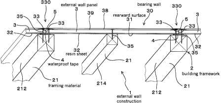
Embodiment 1
The external wall construction according to one
embodiment of the present invention will now be explained based
on Figs. 1 to 5.
The external wall construction 1 according to the present
embodiment as illustrated in Figs. 1 and 2 is arranged as a
bearing wall 30 comprised by fixing a plurality of ceramic type
external wall panels 3 to a building framework 2 of a building.
As illustrated in Fig. 4, a rearward surface 31 of each
external wall panel 3 is backed with a resin sheet 32.
Waterproof tapes 4 are further interposed between the external
wall panels 3 and the building framework 2 as illustrated in
Figs. 1 and 2.
Hard chip cemented boards are employed as the external
wall panels 3 and polyethylene sheets are employed as the resin
sheets 32.
19
CA 02329201 2000-12-20
The building framework 2 is constructed of framing
materials 21 made of timbers.
The resin sheets 32 are backed to the external wall panels
3 through fusion using a laminator.
The thickness of the external wall panels 3 is
approximately 25 mm while the thickness of the resin sheets
32 is approximately 0.5 mm.
As illustrated in Figs. 1 and 3, the external wall
construction 1 is constructed such that lateral end portions
33, upper end portions (lower tongue portions 362) and lower
end portions (upper tongue portions 361 ) of each external wall
panel 3 are disposed on the framing materials 21 constituting
the building framework 2.
The waterproof tapes 4 have elasticity and closely adhere
closely to the resin sheets 32 of the external wall panels 3
and the buildingframework2, respectively. More particularly,
the waterproof tapes 4 adhere closely to both; the resin sheets
32 backed on the rearward surfaces 31 of the external wall panels
3 and the framing materials 21 constituting the building
framework 2.
As illustrated in Fig. 1, laterally neighboring external
wall panels 3 constituting the bearing wall 30 form butt
portions 330 with respective lateral end portions 33 being
abutted to each other. Further , as illustrated in Fig. 3,
vertically neighboring external wall panels 3 form shiplap
joint portions 36 with an upper tongue portion 361 formed at
a lower end portion of one panel and a lower tongue portion
362 formed at an upper end portion of another panel being joined
through straight scarf joint. As illustrated in Fig. 5,
covering materials 5, which comprise elastic joint finishing
CA 02329201 2000-12-20
materials 51 and mesh-like bodies 52 disposed therein, are
provided on front surfaces of the butt portions 330 and the
shiplap joint portions 36.
As illustrated in Figs. 1 and 3, a coating material 38
is applied on the front surface 39 of bearing wall 30. More
particularly, the coating material 38 is applied over the entire
front surface 39 of the bearing wall 30 including also the
surface of the covering materials 5. Note that elastic
caulking materials 331 are preliminarily installed to the lower
tongue portions 362 formed at upper end portions of the lower
external wall panels 3 of the shiplap joint portions 36.
Constructing methods of the external wall construction
1 of the present embodiment will now be explained.
As illustrated in Fig. 2, the building framework 2 is
first assembled through framing materials 21 made of timbers.
More particularly, the building framework 2 is assembled onto
a foundation 20 using framing materials 21 as a base 211,
continuous columns 212, girths 213, and studs 214.
Thereafter, the waterproof tapes 4 are adhered to framing
materials 21 as the continuous columns 212 and girths 213. A
plurality of external wall panels 3 preliminarily backed with
resin sheets 32 (see Fig. 3) is then adhered to the waterproof
tapes 4 by abutting lateral end portions 33 of the panels to
each other. The bearing wall 30 is completed by fixing the
external wall panels 3 to the building framework 2 by driving
nails 35 into the building framework 2 from above the external
wall panels 3 (see Fig. 1) .
The covering materials 5 are further provided on the
shiplap joint portions 36 of the external wall panels 3 as
illustrated in Fig. 5.
21
I
CA 02329201 2000-12-20
Thereafter, the coating material 38 is applied onto the
entire front surface 39 of the bearing wall 30 as illustrated
in Figs. 3 and 5.
Actions and effects of the present embodiment will now
be explained.
As explained above, the external wall construction 1
comprises the building framework 2 and the plurality of external
wall panels 3. Thus, the external wall construction 1 has
simple arrangement and may be easy to be constructed.
Decreases in material costs can also be achieved due to the
small number of constituents.
Further, since the external wall panels 3 are formed by
backing resin sheets 32 on rearward surfaces 31 thereof, cracks
or chippings (see Fig. 21) of the rearward surfaces 31 of the
external wall panels 3 caused through face-nailing can be
prevented. Accordingly, water or carbon dioxide will not be
absorbed from the cracks or chippings formed on the rearward
surfaces 31 so that no dimensional changes of the external wall
panels 3 will be caused, and carbonation or neutralization will
not be promoted. It is thereby possible to obtain an external
wall construction 1 of superior durability.
Waterproof tapes 4 are interposed between the external
wall panels 3 and the building framework 2 . More particularly,
the waterproof tapes 4 are interposed between the resin sheets
32 backed on the rearward surfaces 31 of the external wall panels
3 and the framing materials 21 constituting the building
framework 2 (see Figs. 1 and 3).
In this manner, penetration of water from between the
external wall panels 3 and the building framework 2 on the butt
portions 330 or rearward surfaces of shiplap joint portions
22
CA 02329201 2000-12-20
36 can be reliably prevented.
It has also been enabled with this arrangement to omit
a separate step for constructing waterproof sheets (reference
numeral 94 in Figs. 19 and 20) as it had been necessary in
conventional structures for constructing exterior walls.
Thereby further simplification of the external wall
construction 1 and, moreover, further simplification of
construction are achieved.
The external wall panels 3 has a thickness of
approximately 25 mm, thereby a sufficient strength of the
external wall construction 1 can be secured while further making
constructions easy.
By the arrangement of directly disposing the lateral end
portions 33 of the external wall panels 3 onto the framing
materials 21 constituting the building framework 2, an external
wall construction 1 of more superior strength can be obtained.
Since the waterproof tapes 4 have elasticity, close
contact between the external wall panels 3 and the building
framework 2 can be achieved and thereby penetration of water
from clearances formed between these members is prevented
reliably.
Laterally neighboring external wall panels 3
constituting the bearing wall 30 form butt portions 330, and
vertically neighboring external wall panels 3 form shiplap
joint portions 36. Covering materials 5 are provided on front
surfaces of the butt portions 330 and the shiplap joint portions
36 (see Fig. 5).
With this arrangement, penetration of water from the butt
portions 330 or shiplap joint portions 36 can be reliably
prevented while it is enabled to secure sufficient strength
23
CA 02329201 2000-12-20
of the sh.iplap joint portions 36. It is further possible to
obtain an external wall construction 1 of superior outward
design with no joint portions of external wall panels 3 standing
out.
Since the coating material 38 is applied on the front
surface 39 of the bearing wall 30, it is enabled to obtain an
external wall construction 1 of superior outward design. It
is also possible to prevent reliably the external wall panels
3 from absorbing water or carbon dioxide from the rearward
surfaces 31 of the panels, and dimensional changes of the
external wall panels 3 and promotion of carbonization or
neutralization can be reliably prevented. Thus, itispossible
to obtain an external wall construction 1 of more superior
durability.
As explained so far, the present embodiment is capable
of providing an external wall construction improving
workability, waterproof properties and durability of a bearing
wall.
Embodiment 2
The present embodiment is an example employing foam
polyethylene sheets 321 as the resin sheets 32 to be backed
to the ceramic type external wall panels 3 as illustrated in
Fig. 6.
The thickness of the resin sheets 32 is approximately
2.0 mm.
The remaining arrangements are identical to those of
Embodiment 1.
The resin sheets 32 of this example have remarkable
elasticity since the resin sheets 32 are foamed bodies
24
CA 02329201 2000-12-20
(closed-cell structures). Thus, adhesion with the waterproof
tapes 4 interposed between the building framework 2 and the
external wall panels 3 may be performed in a more reliable
manner.
Thus, it is possible to obtain an external wall
construction of more superior waterproof properties.
The external wall construction of the present embodiment
have extremely high resistance to impact applied through
face-nailing so that cracks or chippings formed on rearward
surfaces 31 of the external wall panels 3 can be more reliably
prevented.
The present embodiment further have actions and effects
identical to those of Embodiment 1.
Embodiment 3
In this embodiment, the resin sheets 32 to be backed to
the ceramic type external wall panels 3 are obtained by
overlaying foam polyethylene sheets 321 and polyethylene
terephthalate nonwoven cloths 322, as illustrated in Fig. 7.
More particularly, the foam polyethylene sheets 321 are
backed to the rearward surfaces 31 of the external wall panels
3, whereon the polyethylene terephthalate nonwoven cloths 322
are backed as illustrated in Fig. 7.
The thickness of the resin sheets 32 is approximately
1.5 mm.
The remaining arrangements are identical to those of
Embodiment 1.
In this arrangement, each resin sheet 32 comprises
laminated foam layer and resin layer. Therefore, the
mechanical strength of the sheets as backing materials is
CA 02329201 2000-12-20
substantially improved.
Accordingly, it is possible to obtain an external wall
construction having even superior waterproof properties and
durability.
The present embodiment further have actions and effects
identical to those of Embodiment 1.
Embodiment 4
The external wall construction according to embodiment
4 of the present invention will now be explained based on Figs.
8 to 13.
As illustrated in Figs. 8 and 9, the external wall
construction 1 according to the present embodiment is arranged,
wherein a bearing wall 30 is constructed by fixing a plurality
of ceramic type external wall panels 3 to a building framework
2 of a building. The building framework 2 is comprised of a
base 22, continuous columns 23, girths 24, and studs 26.
Each external wall panel 3 is arranged by backing a resin
sheet 32 on a rearward surface 31 of the panel (see Fig. 4).
Further, waterproof tapes 4 are interposed between rearward
surfaces 31 of the external wall panels 3 at peripheral end
portions 34 thereof and the building framework 2 as illustrated
in Figs. 8 and 9.
The girths 24 become framing materials in horizontal
directions as illustrated in Fig. 9, with a plurality of notched
grooves 241 for ventilation purposes being formed on surfaces
of the girths contacting the rearward surfaces 31 of the
external wall panels 3 as to be across in vertical directions
as illustrated in Figs. 8 and 11.
Hard chip cemented boards are employed as the external
26
CA 02329201 2000-12-20
wall panels 3. Polyethylene sheets are used as the resin sheets
32 and are backed to the external wall panels 3 through fusion
using a laminator.
The thickness of the external wall panels 3 is
approximately 15 mm while the thickness of the resin sheets
32 is approximately 0.5 mm.
As illustrated in Figs . 8, the external wall construction
1 is constructed such that lateral end portions 33 of laterally
arranged external wall panels 3 are disposed on the continuous
columns 23 constituting the building framework 2. As
illustrated in Fig. 10, the joint portions of the vertically
arranged external wall panels 3 are arranged such that a lower
tongue portion 362 formed on an upper end portion of a lower
panel and an upper tongue portion 361 formed on a lower end
portion of an upper panel are disposed on the girths 24.
The waterproof tapes 4 exhibit elasticity and are closely
adhering to the resin sheets 32 backed to the rearward surfaces
31 of the external wall panels 3 and the base 22, continuous
columns 23, and the girths 24, respectively, as illustrated
in Fig. 9. With this arrangement, the rearward surfaces 31 of
the external wall panels 3 are closely adhered to the building
framework 2 at peripheral end portions 34 of the panels.
Further, as illustrated in Fig. 11, a plurality of notched
grooves 241 is formed on one lateral surface of each girth 24
in directions perpendicular to the length direction of the girth
24.
The girths 24 are assembled to the continuous columns
23 such that lateral surfaces with the notched grooves 241
formed on the girths 24 facing to the side to which the external
wall panels 3 are fixed, that is, to the outdoor side, as
27
CA 02329201 2000-12-20
illustrated in Fig. 8.
Therefore, ventilation paths through which air 7 is
released are formed in vertical directions between the rearward
surfaces 31 of the external wall panels 3 and the notched grooves
241 (see Figs. 8, 12 (A) and 12 (B) ) .
For instance, it is assumed that in the girth 24 of Fig.
11, each notched groove 241 has a depth D of 15 mm, and a width
W of 25 mm while each convex streak portion 242 formed between
neighboring notched grooves 241 has a width V of 25 mm.
As illustrated in Fig. 12(A), the external wall panels
3 are face-nailed to the girths 24 at the convex streak portions
242. Intervals for driving the nails 35 are set to be 100 mm
for forming the bearing wall 30.
Further, as illustrated in Figs . 8 and 12 (A) , laterally
neighboring external wall panels 3 constituting the bearing
wall 30 form butt portions 330 with respective lateral end
portions 33 being abutted to each other. Further, vertically
neighboring external wall panels 3 form shiplap joint portions
36 with an upper tongue portion 361 formed at a lower end portion
of one panel and a lower tongue portion 362 formed at an upper
end portion of another panel being j oined through straight scarf
joint, as illustrated in Fig. 10. Covering materials 5, which
are comprised of elastic joint finishing materials 51 and
mesh-like bodies 52 disposed therein, are provided on front
surfaces of the butt portions 330 and the shiplap joint portions
36 (see Fig. 5) .
Coating material 38 is applied on the front surface 39
of bearing wall 30 as illustrated in Figs. 8 and 10. More
particularly, the coating material 38 is applied over the entire
front surface 39 of the bearing wall 30 including also the
28
CA 02329201 2000-12-20
surface of the covering materials 5. Note that elastic
caulking materials 331 are preliminarily installed to the lower
tongue portions 362 formed at upper end portions of the lower
external wall panels 3 of the shiplap joint portions 36. By
overlapping the upper tongue portions 361 onto the lower tongue
portions 362, the elastic caulking materials 331 are pressed
and deformed and thereby joint of the vertically arranged
external wall panels 3 is performed reliably.
Constructing methods of the external wall construction
1 of the present embodiment will now be explained.
As illustrated in Fig. 9, the building framework 2 is
first assembled from timbers. More particularly, the building
framework 2 is obtained by assembling a base 22, continuous
columns 23, girths 24, and studs 26 onto a foundation 20.
The continuous columns 23 and the girths 24 are
respectively formed with notched portions 233 and 243 as
illustrated in Fig. 13, and both members are joined by fitting
these notched portions 233 and 243 with each other.
Thereafter, the waterproof tapes 4 are adhered to the
base 22, continuous columns 23 and girths 24 of the building
framework 2. A plurality of external wall panels 3
preliminarily backed with resin sheets 32 (see Fig. 10) is then
adhered from above the waterproof tapes 4 by abutting lateral
end portions 33 of the panels to each other. The integrally
formed bearing wall 30 is completed by fixing the external wall
panels 3 to the building framework 2 by driving nails 35 into
the building framework 2 from the surface sides of the external
wall panels 3 (see Fig. 8).
The covering materials 5 are further provided on the butt
portions 330 and the shiplap joint portions 36 of the external
29
CA 02329201 2000-12-20
wall panels 3 as illustrated in Fig. 8.
The coating material 38 is thereafter applied onto the
entire front surface 39 of the bearing wall 30 as illustrated
in Figs. 8 and 10.
Actions and effects of the present embodiment will now
be explained.
As explained above, the external wall construction 1
comprises the building framework 2 and the plurality of external
wall panels 3. The external wall construction 1 is thus of
simple arrangement and may be easy to be constructed.
Decreases in material costs can also be achieved due to the
small number of constituents.
Owing to the fact that the external wall construction
1 does not utilize furring strips as conventional structures
do, the overall thickness can be reduced to contribute to
increase effective indoor spaces of buildings.
Further, since the external wall panels 3 are formed by
backing resin sheets 32 on rearward surfaces 31 thereof, cracks
or chippings (see Fig. 21) of the rearward surfaces 31 of the
external wall panels 3 caused through face-nailing can be
prevented. Accordingly, water or carbon dioxide will not be
absorbed from the cracks or chippings formed on the rearward
surfaces 31 so that no dimensional changes of the external wall
panels 3 will be caused, and carbonation or neutralization will
not be promoted. It is thereby possible to obtain an external
wall construction 1 of superior durability.
Waterproof tapes 4 are interposed between the external
wall panels 3 and base 22, continuous columns 23, and girths
24. The resin sheets 32 backed to the rearward surfaces of the
ceramic type external wall panels 3 serve as waterproof sheets
CA 02329201 2000-12-20
(see Figs. 8 and 10).
In this manner, penetration of water from clearances
formed in joint portions between the external wall panels 3
at rearward surfaces of the butt portions 330 or shiplap j oint
portions 36 can be reliably prevented.
Notched grooves 241 for ventilation purposes are formed
on the girths 24 of the building framework 2 on surfaces of
the girths 24 contact the external wall panels 3. Thus,
ventilation of the interior of the external wall panels 3 can
be secured. More particularly, as illustrated in Fig. 12(B),
air 7 is enabled to pass through the external wall panels 3
and the notched grooves 241.
With this arrangement, air 7 of high temperature and
humidity in the interior of the building is passed upward and
will not be accumulated at rearward surfaces 31 of the external
wall panels 3 or peripheries thereof. Thus, air 7 of high
temperature and humidity can be prevented from condensing on
rearward surfaces 31 of the external wall panels 3, the building
framework 2, or heat insulators (not shown in the drawing)
disposed on indoor sides of the external wall panels 3.
Accordingly, it is possible to obtain an external wall
construction 1 of superior durability free of corrosion of the
building framework 2.
The external wall panels 3 have a thickness of
approximately 15 mm, whereby a sufficient strength of the
external wall construction 1 can be secured while further
constructions become easy.
Moreover, since the peripheral end portions 34 of the
external wall panels 3 are directly fixed to the building
framework 2 through nails 35, it is possible to obtain an
31
CA 02329201 2000-12-20
external wall construction 1 having even superior strength.
Since the waterproof tapes 4 have elasticity, close
contact between the external wall panels 3 and the building
framework 2 can be achieved, thereby penetration of water from
clearances formed between these members can be prevented
reliably.
Laterally neighboring external wall panels 3
constituting the bearing wall 30 form butt portions 330, and
vertically neighboring external wall panels 3 form shiplap
joint portions 36. Covering materials 5 are further provided
on front surfaces of the butt portions 330 and the shiplap joint
portions 36 (see Fig. 5).
With this arrangement, penetration of water from the butt
portions 330 or shiplap joint portions 36 can be reliably
prevented while it is enabled to secure sufficient strength
of the shiplap joint portions 36. It is further possible to
obtain an external wall construction l of superior outward
design with no joint portions of external wall panels 3 standing
out.
Since the coating material 38 is applied on the front
surface 39 of the bearing wall 30, it is enabled to obtain an
external wall construction 1 of superior outward design. It
is also possible to prevent reliably the external wall panels
3 from absorbing water or carbon dioxide from the rearward
surfaces 31 of the panels, and dimensional changes of the
external wall panels 3 and promotion of carbonization or
neutralization can be reliably prevented. It is thus possible
to obtain an external wall construction 1 having even superior
durability.
As explained so far, the present embodiment is capable
32
CA 02329201 2000-12-20
of arranging a bearing wall having superior workability,
waterproof properties and durability and providing an external
wall construction of superior ventilating properties.
It should be noted that while polyethylene sheets are
employed as resin sheets in the present embodiment, it is also
possible to employ foam polyethylene sheets 321 (see Fig. 11)
as in Embodiment 2 or to employ sheets in which foam polyethylene
sheets 321 and polyethylene terephthalate nonwoven cloths 322
are overlaid (Fig. 7). In this Embodiment, similarly to
Embodiments 2 and 3, waterproof properties; durability and
impact-resistance can thus be further improved.
Embodiment 5
The present embodiment is an example of an external wall
construction l0 as illustrated in Figs. 14 to 16(B) in which
supporting columns 25 are fixed to lateral sides of continuous
columns 23 comprising framings in vertical directions of the
building framework 2.
More particularly, supporting columns 25 are fixed to
both lateral sides of the continuous columns 23 using through
bolts, as illustrated in Fig. 16(B). The supporting columns
25 are dimensioned in that they are shorter than the continuous
columns 23, smaller in thickness in right and left directions,
and identical in width in front and rear directions . Note that
the terms "right and left directions" and "front and rear
directions" denote right and left directions and front and rear
directions when facing the outdoor side of the external wall
constructing structure 10.
As illustrated in Fig. 16(B), the girths 24 are fixed
to the supporting columns 25 and the continuous columns 23 with
33
CA 02329201 2000-12-20
end portions of the girths 24 mounted on upper ends 251 of the
supporting columns 25.
More particularly, two dowel holes are formed on each
upper end 251 of the supporting columns 25 as illustrated in
Fig. 16 (A) , wherein dowels 253 are pounded into the dowel holes
while half portions of the dowels are projected upward.
On the other hand, dowel holes are similarly formed on
upper and lower lateral surfaces at end portions of the girths
24.
By fitting the dowels 253 of the supporting columns 25
to the dowel holes formed on lateral surfaces at lower sides
of the girths 24, the girths 24 are fixed to the upper ends
251 of the supporting columns 25.
Dowels 243 are also pounded into the dowel holes formed
on lateral surfaces at upper sides of the girths 24 . Additional
supporting columns 25 are piled on the girths 24 by fitting
the dowel holes formed on lower end butt ends 252 of the columns
with the dowels 243 and are fixed to extend along the continuous
columns 23.
The external wall constructing structure 10 as
illustrated in Fig. 15 is then completed by fixing the ceramic
type external wall panels 3 onto the building framework 2
arranged in the above manner.
More particularly, in the external wall constructing
structure 10, ceramic type external wall panels 3 backed with
resin sheets 32 on rearward surfaces 31 thereof are face-nailed
to the building framework 2 with the waterproof tapes (not shown
in the drawings) being interposed therebetween:
Further, as illustrated in Fig. 15, the lateral end
portions of the ceramic type external wall panels 3 are fixed
34
CA 02329201 2000-12-20
to the continuous columns 23 by driving nails 35 therein. The
vertical end portions of the ceramic type external wall panels
3 are fixed to the girths 24 by driving nails 35 therein.
The remaining arrangements are identical to those of
Embodiment 4.
According to the present embodiment, it is possible to
reinforce the continuous columns 23, and thereby strength of
the building framework 2 is secured. The girths 24 can be easily
and reliably fixed to the continuous columns 23 through the
supporting columns 25.
The present embodiment further exhibits actions and
effects identical to those of Embodiment 4.
Embodiment 6
The present embodiment is an example of an external wall
construction 100 as illustrated in Figs. 17, Fig. 18(A) and
Fig. 18 (B) in which the continuous columns 23 and the supporting
columns 25 have identical sectional dimensions.
In the present embodiment, a width GV of the notched
grooves 241 for ventilation and a width V of convex streak
portions 242 are set to be larger than those of Embodiment 5.
More particularly, both the width W of the notched grooves 241
and the width V of the convex streak portions 242 are 50 mm.
Nails 35 are driven into all of the convex streak portions
242 as illustrated in Fig. 17 for fastening the ceramic type
external wall panels 3 to the building framework 2. Lateral
end portions of the ceramic type external wall panels 3 are
fixed to the supporting columns 25 by driving nails 35.
The remaining arrangements are identical to those of
Embodiment 4.
CA 02329201 2000-12-20
With this arrangement, identical block materials can be
used for the continuous columns 23 and the supporting columns
25 by merely adjusting their lengths so that it is possible
to further decrease costs for construction. The present
embodiment further has actions and effects identical to those
of Embodiment 4.
It is obvious that various modification or changes of
the present invention may be performed in light of the above
techniques . Therefore, it should be understood that the present
invention may be embodied in various ways other than those
described herein without departing from the scope of the
following claims.
36