Language selection

Search

Patent 2329222 Summary

Third-party information liability

Some of the information on this Web page has been provided by external sources. The Government of Canada is not responsible for the accuracy, reliability or currency of the information supplied by external sources. Users wishing to rely upon this information should consult directly with the source of the information. Content provided by external sources is not subject to official languages, privacy and accessibility requirements.

Claims and Abstract availability

Any discrepancies in the text and image of the Claims and Abstract are due to differing posting times. Text of the Claims and Abstract are posted:

  • At the time the application is open to public inspection;
  • At the time of issue of the patent (grant).
(12) Patent: (11) CA 2329222
(54) English Title: ESCALATOR ROLLER DEGRADATION MONITOR DEVICE
(54) French Title: DISPOSITIF DE SURVEILLANCE DE LA DETERIORATION DE ROULEAUX D'ESCALATEUR
Status: Expired
Bibliographic Data
(51) International Patent Classification (IPC):
  • B66B 27/00 (2006.01)
  • B66B 23/08 (2006.01)
(72) Inventors :
  • VON OFFERMAN, KIRK (United States of America)
  • NORTH, ROBERT T. (United States of America)
  • SMITH, MELANIE JEAN (United States of America)
  • KAO, MICHAEL D. (United States of America)
  • FRAZIER, ROGER L. (United States of America)
  • BONITZ, WILLIAM (United States of America)
(73) Owners :
  • INVENTIO AG (Switzerland)
(71) Applicants :
  • INVENTIO AG (Switzerland)
(74) Agent: RICHES, MCKENZIE & HERBERT LLP
(74) Associate agent:
(45) Issued: 2007-02-13
(22) Filed Date: 2000-12-20
(41) Open to Public Inspection: 2001-06-21
Examination requested: 2003-11-13
Availability of licence: N/A
(25) Language of filing: English

Patent Cooperation Treaty (PCT): No

(30) Application Priority Data:
Application No. Country/Territory Date
09/468,567 United States of America 1999-12-21

Abstracts

English Abstract

A roller degradation monitor device monitors the diameter of escalator rollers during operation of the escalator. A cam plate is mounted proximate the roller track for sequential contact with the upper circumference of rollers as they travel along the track. The vertical displacement of the cam plate is monitored by a proximity switch or sensor, differences in cam plate practice from an established baseline signifying variations in roller diameter. The output of the proximity switch or sensor provides a continuous measure of wear and decrease in diameter of the rollers. When the wear exceeds a predetermined value an alarm can be actuated.


French Abstract

Dispositif de surveillance de la dégradation des rouleaux d'escalateur qui surveille le diamètre des rouleaux d'escalateur pendant que ce dernier fonctionne. Un disque à cames est installé près du rail des rouleaux aux fins de contact séquentiel avec la circonférence supérieure des rouleaux alors qu'ils se déplacent le long du rail. Le déplacement vertical des disques à cames est surveillé par un détecteur ou un capteur de proximité, les différences de pratique des disques à cames à partir des conditions de base établies signifiant des variations de diamètre des rouleaux. La sortie du détecteur ou du capteur de proximité fournit une mesure continue de l'usure et de la réduction du diamètre des rouleaux. Lorsque l'usure dépasse une valeur prédéterminée, une alarme peut être actionnée.

Claims

Note: Claims are shown in the official language in which they were submitted.


We claim:

1. An apparatus for monitoring the wear of escalator rollers traveling along a
track, said track forming a closed path for the rollers, comprising a bracket
mounted to the
track;
a proximity switch :mounted to the bracket and having an actuator;
and a cam plate coupled to the actuator positioned and arranged for contact
with at least one of the rollers arc the rollers travel along the track;
the proximity switch generating a signal when the displacement of the cam
plate as a result of roller wear equals or exceeds a preset value.
2. The apparatus of claim 1, wherein the proximity switch is of the
proportional
type.
3. The apparatus of claim 1, wherein the cam plate is positioned and arranged
for continuous contact with one of the rollers as the roller makes at least
one half of a
revolution along the track.
4. The apparatus of claim 2, wherein the cam plate is positioned and arranged
for contact with the rollers by gravity.
5. The apparatus of claim 4, wherein the cam plate is connected to the bracket
by a linkage for maintaining the cam plate parallel to the track.


6. The apparatus of claim 3 wherein the cam plate has a roller contact length
equal to a spacing between adjacent rollers.
7. The apparatus of claim 3, wherein the cam plate is positioned and arranged
for contact with the rollers by gravity.
8. The apparatus of claim 7, wherein said cam plate is connected to the
bracket
by a linkage for maintaining the c:am plate parallel to the track.
6

Description

Note: Descriptions are shown in the official language in which they were submitted.


CA 02329222 2000-12-20
ESCALATOR ROLLER DEGRADATION MONITOR DEVICE
The present invention relates to a new and improved apparatus for monitoring
the
wear of the rollers utilized in escalators and similar conveyers and
generating a signal when
the roller has worn beyond a specified amount.
Back~ound of the Invention
Escalators and similar conveyor-like devices which incorporate a series of
moving
platforms or step elements that are typically mounted for travel along a
closed loop of a
guidance track. As the rollers are: primary load-bearing means for the steps
or platforms,
they are subject to continuous wear. It is important that the rollers be
monitored for the
extent of wear to prevent degradation in escalator performance or failure.
Heretofore
inspection of the rollers would lave been performed manually, requiring
placing the
escalator out of service for such inspection and often requiring some
disassembly to allow
service personnel access to the rollers. The entire length of the step or
platform
components would have to be inspected.
It is accordingly a purpose of the present invention to provide an apparatus
which
allows the automated monitoring of the roller condition of escalators and
similar conveyor-
like devices.
A further purpose of the present invention is to provide an apparatus which
allows
monitoring of escalator rollers and the like to be performed on a continuous
basis.
Still a further purpose of the present invention is to provide such an
apparatus which
allows continuous monitoring of the condition of escalator rollers and the
like during


CA 02329222 2000-12-20
operation, and which can generate a signal which alerts maintenance personnel
that such
maintenance or service of the escalator is due.
Brief Description of the Drawing
A fuller understanding of the present invention will be obtained upon
consideration
of the following detailed description of a preferred, but nonetheless
illustrative embodiment
of the invention, when reviewed vi conjunction with the annexed drawings,
wherein:
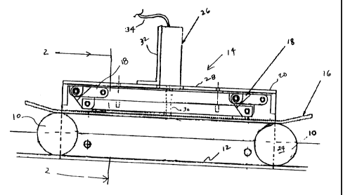
FIG. 1 is a side elevation view of the present invention mounted in
conjunction with
an escalator.roller assembly; and
FIG. 2 is a sectional elevation view taken along Line 2-2 in FIG. 1.
Detailed Descnption of the IBVention
With reference to the Figures, escalator rollers 10, of which only two are
shown in
Figure 1, are ganged together in a continuous chain, and are constrained to
travel along a
roller track 12. The track describes a continuous closed path along which the
rollers run,
the rollers being affixed to the traveling escalator steps, which are driven
by an appropriate
motor source (not shown). Wear-sensing apparatus 14 comprises a cam or similar
sensor
plate 16 mounted by a pair of linkages 18 to apparatus bracket 20. As shown,
bracket 20
may be in the form of an inverted L, the vertical leg 22 of which being
affixed to the
vertical side wall portion 24 of escalator roller track 12 by the use of
appropriate fasteners,
such as rivets or shallow head bolts. A proximity switch or sensor 26 is
mounted by support
32 to the horizontal leg 28 of the bracket 20, and has an activator 30. As
known in the art,
2


CA 02329222 2000-12-20
the proximity switch is capable of generating an electrical signal
representing the vertical
positioning of the cam plate. The linkages 18 allow the cam plate to rest upon
the rollers
10, under the influence of gravity, whereby the output of the proximity switch
26 reflects
the height of the cam plate which is in turn indicative of the diameter of the
rollers. As
the rollers wear their diameter decreases, the cam plate further dropping, the
proximity
sensor subsequently generating a changed signal reflective of such a change.
While the
proximity switch depicted in the figures is shown having a mechanical-type
activator 30, it
is to be recognized that the proximity switch may also be of the non-contact
type, where the
distance of the cam plate from the proximity switch is determined without the
need for a
physical connection therebetween.. The cable 34 couples the switch output,
either in the
form of an alarm signal or in the form of a proportional output for further
processing, to
the associated alarm or processing circuitry and equipment as known.
Preferably, the length of the cam plate is such that one roller is inspected
individually for at least one-half revolution. Prior to the roller leaving the
cam plate the
next roller is introduced to reducE: motion of the cam plate. As known in the
art, the
linkages 18 are chosen to be of the type that maintains the cam plate parallel
to the roller
track, so that the position of the cam plate is not influenced by the position
of the roller
as it passes thereunder. Other types of linkages, such as a hinge having its
pivot axis
parallel to the direction of travel for the rollers, that is, along the length
of the cam plate,
can similarly be employed. This prevents the proximity switch from generating
an
erroneous signal resulting from cocking of the cam plate as a roller travels
therealong and
reduces the need for processing software to determine the position of a roller
to
compensate therefor. With the apparatus mounted above the rollers, typically
on the return
3


CA 02329222 2000-12-20
side of the track, the cam rests on the rollers under the influence of
gravity, thus
eliminating the need for external biasing, such as a spring mechanism, to
maintain the roller
in contact with the cam and track: with excess wear on the roller. If
necessary, however, a
slight spring force may be added to insure roller contact with the track and
cam and thus
generate true diameter readings.
The proximity switch or sensor 26 may be of the proportional type, generating
an
output corresponding to the position of the actuator or may be of the on/off
type, whereby
the switch is preset to change state at a given position of the actuator,
corresponding to a
wear displacement of a chosen degree. With a proportional-type sensor, the
electronic
associated with the proximity switch 26 can provide for adjustability in the
amount of wear
which generates an output signal. 'typically, wear on the order of 1/8 inch
from the original
diameter of the rollers should tri;ager an output. Such output may be in the
form of a
remote indicator, such as a lamp, and may also include an interlock function
which shuts
down the escalator automatically, requiring manual acknowledgment of the
signal and
resetting thereof. Alternatively, or in conjunction with other signaling, a
continuous readout
of the roller diameter and/or its wear from an initial size may be displayed.
4

Representative Drawing
A single figure which represents the drawing illustrating the invention.
Administrative Status

For a clearer understanding of the status of the application/patent presented on this page, the site Disclaimer , as well as the definitions for Patent , Administrative Status , Maintenance Fee  and Payment History  should be consulted.

Administrative Status

Title Date
Forecasted Issue Date 2007-02-13
(22) Filed 2000-12-20
(41) Open to Public Inspection 2001-06-21
Examination Requested 2003-11-13
(45) Issued 2007-02-13
Expired 2020-12-21

Abandonment History

There is no abandonment history.

Payment History

Fee Type Anniversary Year Due Date Amount Paid Paid Date
Registration of a document - section 124 $100.00 2000-12-20
Application Fee $300.00 2000-12-20
Maintenance Fee - Application - New Act 2 2002-12-20 $100.00 2002-11-25
Request for Examination $400.00 2003-11-13
Maintenance Fee - Application - New Act 3 2003-12-22 $100.00 2003-12-02
Maintenance Fee - Application - New Act 4 2004-12-20 $100.00 2004-11-25
Maintenance Fee - Application - New Act 5 2005-12-20 $200.00 2005-11-28
Final Fee $300.00 2006-11-02
Maintenance Fee - Application - New Act 6 2006-12-20 $200.00 2006-11-29
Maintenance Fee - Patent - New Act 7 2007-12-20 $200.00 2007-11-23
Maintenance Fee - Patent - New Act 8 2008-12-22 $200.00 2008-11-20
Maintenance Fee - Patent - New Act 9 2009-12-21 $200.00 2009-12-04
Maintenance Fee - Patent - New Act 10 2010-12-20 $250.00 2010-12-09
Maintenance Fee - Patent - New Act 11 2011-12-20 $250.00 2011-12-08
Maintenance Fee - Patent - New Act 12 2012-12-20 $250.00 2012-12-03
Maintenance Fee - Patent - New Act 13 2013-12-20 $250.00 2013-12-09
Maintenance Fee - Patent - New Act 14 2014-12-22 $250.00 2014-12-08
Maintenance Fee - Patent - New Act 15 2015-12-21 $450.00 2015-12-07
Maintenance Fee - Patent - New Act 16 2016-12-20 $450.00 2016-12-13
Maintenance Fee - Patent - New Act 17 2017-12-20 $450.00 2017-12-11
Maintenance Fee - Patent - New Act 18 2018-12-20 $450.00 2018-12-10
Owners on Record

Note: Records showing the ownership history in alphabetical order.

Current Owners on Record
INVENTIO AG
Past Owners on Record
BONITZ, WILLIAM
FRAZIER, ROGER L.
KAO, MICHAEL D.
NORTH, ROBERT T.
SMITH, MELANIE JEAN
VON OFFERMAN, KIRK
Past Owners that do not appear in the "Owners on Record" listing will appear in other documentation within the application.
Documents

To view selected files, please enter reCAPTCHA code :


To view images, click a link in the Document Description column. To download the documents, select one or more checkboxes in the first column and then click the "Download Selected in PDF format (Zip Archive)" or the "Download Selected as Single PDF" button.

List of published and non-published patent-specific documents on the CPD .

If you have any difficulty accessing content, you can call the Client Service Centre at 1-866-997-1936 or send them an e-mail at CIPO Client Service Centre.


Document
Description 
Date
(yyyy-mm-dd) 
Number of pages   Size of Image (KB) 
Representative Drawing 2001-06-22 1 11
Cover Page 2007-01-19 1 42
Cover Page 2001-06-22 1 39
Abstract 2000-12-20 1 17
Description 2000-12-20 4 150
Claims 2000-12-20 2 35
Drawings 2000-12-20 1 17
Representative Drawing 2007-01-19 1 12
Correspondence 2001-01-29 1 23
Assignment 2000-12-20 2 90
Assignment 2001-03-19 7 243
Correspondence 2001-03-19 3 103
Assignment 2000-12-20 4 147
Prosecution-Amendment 2003-11-13 1 32
Correspondence 2006-11-02 1 44