Language selection

Search

Patent 2329327 Summary

Third-party information liability

Some of the information on this Web page has been provided by external sources. The Government of Canada is not responsible for the accuracy, reliability or currency of the information supplied by external sources. Users wishing to rely upon this information should consult directly with the source of the information. Content provided by external sources is not subject to official languages, privacy and accessibility requirements.

Claims and Abstract availability

Any discrepancies in the text and image of the Claims and Abstract are due to differing posting times. Text of the Claims and Abstract are posted:

  • At the time the application is open to public inspection;
  • At the time of issue of the patent (grant).
(12) Patent Application: (11) CA 2329327
(54) English Title: ALUMINUM ELECTROLYTE CAPACITOR
(54) French Title: CONDENSATEUR ELECTROLYTIQUE EN ALUMINIUM
Status: Dead
Bibliographic Data
(51) International Patent Classification (IPC):
  • H01G 2/08 (2006.01)
  • H01G 9/08 (2006.01)
(72) Inventors :
  • BEIER, DIETER (Germany)
  • DANZER, KLAUS (Germany)
  • FETZER, JURGEN (Germany)
  • GAYER, MANFRED (Germany)
  • NIEDERBERGER, GERHARD (Germany)
  • NEUMEISTER, STEPHAN (Germany)
  • RAIBLE, CHRISTOPH (Germany)
  • REDER, THOMAS (Germany)
  • SCHWEIKERT, WILHELM (Germany)
  • SPRINGMANN, WALTER (Germany)
  • WILL, NORBERT (Germany)
(73) Owners :
  • EPCOS AG (Germany)
(71) Applicants :
  • EPCOS AG (Germany)
(74) Agent: FETHERSTONHAUGH & CO.
(74) Associate agent:
(45) Issued:
(86) PCT Filing Date: 1999-04-08
(87) Open to Public Inspection: 1999-10-28
Availability of licence: N/A
(25) Language of filing: English

Patent Cooperation Treaty (PCT): Yes
(86) PCT Filing Number: PCT/DE1999/001025
(87) International Publication Number: WO1999/054893
(85) National Entry: 2000-10-19

(30) Application Priority Data:
Application No. Country/Territory Date
198 17 493.4 Germany 1998-04-20

Abstracts

English Abstract


The invention relates to an aluminum electrolytic capacitor, especially for
use in capacitor banks, which is mounted in a housing (1) provided with
cooling ribs (2), whereby the housing (1) is produced as an aluminum cast part.


French Abstract

Condensateur électrolytique en aluminium, utilisé notamment dans des batteries de condensateurs, logé dans un boîtier (1) muni d'ailettes de refroidissement (2), caractérisée en ce que le boîtier (1) est constitué par une pièce moulée en aluminium.

Claims

Note: Claims are shown in the official language in which they were submitted.


Claims
1. Aluminum electrolyte capacitor, in particular for
application in capacitor batteries, which is installed in a
housing (1) that is provided with cooling ribs (2),
characterized in that the housing (1) is constructed as an
aluminum casting.
2. Aluminum electrolyte capacitor as claimed in claim 1,
characterized in that the cooling ribs (2) are constructed in
a flat shape at two opposite sides (5, 6) of the housing.
3. Aluminum electrolyte capacitor as claimed in claim 1 or 2,
characterized in that the housing (7) is constructed to accept
a plurality of capacitors (8, 9, 10,.,.).
4. Aluminum electrolyte capacitor as claimed in claim 3,
characterized in that the housing (1) comprises an insulating
coating on its interior side.
5. Aluminum electrolyte capacitor as claimed is claim 3,
characterized in that insulating cups for accepting the
capacitors are disposed in the housing (1).
6. Aluminum electrolyte capacitor as claimed in one or the
claims 1 to 5, characterized in that the connection or a
plurality of capacitors (8, 9, 10,...) is accomplished in a
capacitor battery with the aid of striplines (11) that are
fashioned in the shape a sandwich.
7. Aluminum electrolyte capacitor as claimed in claim 6,
characterized in that the striplines (11) are constructed in
coaxial fashion.
-5-

Description

Note: Descriptions are shown in the official language in which they were submitted.


Oct.l6. 2000 4:27PM CA 02329327 2000-io-i9 Ido.0225 P. 2
'.'aR. '9 8 P 15 4 6
Alum3tlum Electrolyte Capacitor
The invention relates tv an aluminum olovtrolyte capacitor,
particularly for application in rapar_iter batteries, which is
installed in a housing that is provided with cooling ribs.
DE 92 03 739 U1 teaches a housing for electrical capacitors
which consists of plastic, with axial longitudinal ribs
disposed at the housing exterior to improve the heat
dissipation.
In l.he operation of aluminum electrolyte capacitors with
superposed a.c. voltage, a eubdtantial power loan occurs in
the form of h~at by teasers of the relatively high equivalent
series resistance of this component.. Thi A m~»xY ha dissipated
via the housing, whereby the housings of aluminum elecs,roly>re
capaci>rori~ have hitherto consisted of cyliiW~lc;al aluminum
cups that are produced as impact-extrur~ion parts with smooth
wall~. Shrink tubes or plastic cups are typically plea~d on
the aluminum cup as electrical inpulation, with the result
that thp hRat: dissipation ie improved compared to blank
housings. To further improve the heaL~-die~sipation, the
capacitor is mounted U!1 C:UU1111cJ. bWGLa r~r cooling bodies
and/or is air-blasted. This results in additional outlay for
cooling bodies and fixing material. When several electrolyte
capacitors are mounted together in series or parallel circuits
(what are known as capacitor batteries), substantial coezs are
again incurred for the =wyuirCd c;xiar~r~i~.
Heaauee of the high additional costs, the advantage of a
hie~her loading aapaeity based on forced cooling using cooling
bodies has usually noz been exploited. Rather, the circuit
-1-
Received Oct-16-00 Od:l3pm From- To-Smart 8 Biaaar Page 002

Oct.l6. 2000 4~27PM CA 02329327 2000-io-i9 Pda.0225 P. 0
i
C;e~ign ha~ usually been ba:ed on a presumption of natural
tovZimg - ~vi~ in any cdr~e, air cooling.
It i~ the object of the pr~~ent invention to further develop a
capacitor of the type mentioned above such that heat can be
r.7ir~pipat.ed effectively given low production and assembly
cost .
This object is inventively achieved in that the housing is
conratructcd as an aluminum casting.
This achiRVpe rnP ahvantagp that, on one hand, housings of
this type can be produced cost-effectively and are
particularly well-suited to the wiring in capacitr~r bal,l.ot~iar~.
it being pos~ible to realize not only the cooling ribs but
also the gr~ater wall thickneeees that are n~ceaeary for
reducing heat resistance iz~ the radial directioa.
seeides the aforementioned plastic housings triat have cool~.ng
ribs, which are less euite~ble for~electrolyte capacitors,
metallic houeitzga having reeling ribo arc also lcnowa, though
these consist of thin ah~et with cooling ribs that are
shrunken on or welded in place (DE-A-A6509). T'h9~ ~ppa.rate
processing step of shrinking or welding cooling ribs raises
the coats of mamu,Caci:uring such housings substantially, and
containers of thin sheet also comprise a higher heat
resistance in the radial direction than this iz~ the inventive
capacitor having an aluminum casting. jpiE~
Advantageous developments of the subject matter of the
invention are laid out iu the su?st;lr~~.ma,
The invention will now be detailed with reference to
exemplifying embodiments.
-2-
Rocofvod Oct-16-00 04:18pm From- To-Smort i BIiQOr POQO 008

Oct.l6. 2000 4:27FM CA 02329327 2000-io-i9 ~ No.O225 P. 4
Shown are:
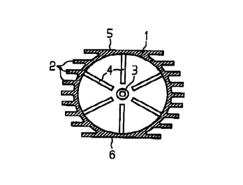
Fig. l: a capacitor hou~ing consisting of an aluminum casting;
Ficd. 2: an embodiment having a multiple housing; and
Fig. 3 and Fig. 4: circ:uiLe3 with a. »LripliuC.
Fig. 1 shows a housing 1 for an aluminum electrolyte capacitor
which consists of an aluminum casting having cooling ribo 2
formed thereon. At the tloor of the housing 1 there ie a
spindle 3 that serves to center the capacitor element.
Radially arranged ribs 4 are also disposed at the floor of the
housing 1, which cervc fer fixing the capacitor clcmcnt is a
vibrastabl~ manner. Th~ heat flow out of the capacitor ~1~m~nt
ocrur~e primarl 1y vi a t:hp prat rub i ng aathodp a.nd. the cup ,
bottom, and accordingly the cooling ribs only achieve their
full effect given low heat resistance along the cup wall. The
housing 1 is constructed flat at two opposite sides, which
creates the possibility of arranging a plurality of capacit:or~
housineds next to cne anothQr as reprapented in Fig. 2 po ap to
conaervp ~par.P _
Ac:c;vraing t~ Fig. Z, the individual housings are loeaLed
within as outer housing 7, thereby guaranteeing s particularly
simple assembly of the multiple housing 7. The individual
haur~ings 1 are arranged With their flat sides 5,6 against one
another.
Fig. 3 shown the parallel Circuit of capacitor elements e, 9,
10,..., which are installed in a housing as represented in Fig.
2. The connection is accomplis~hod by a :tripling 11, which is
constructed ae a simple "aandwi.n'h~~ . An i nsul a.tion 13 ig
located between the two electrodes 12 arid 14. An additional
-3~
_, .. Received .Oct-16-D0 Od:l3pm From- To-Smart ~ Bi~aar PaQA ~Od

Oct.l6. 2000 4~27PM CA 02329327 2000-io-i9 No.0226 P. 6
insulation 15 is disposed beneath ttie electrode lg. The
electxodca 12, 14 arc connocted to the anode terminal lugs 1G
and the cathode terminal lugt3 17, rc~pcctivcly.
Rig. 4 t~how~ a further embodiment of a stripling 11 having a
Coaxial structure. Fig. 4 includes the same reference
characters as Fig. 3.
It ie also pos~ible to lead the negative pole via the houcting
1 - i.e. via the terminating ahe~t - and to connect th~
positive pole externally.
It is also possible to insert am izisulxLlnr~ c; up ~t~aae yr
plaptic (dccp draw part) into the metal housing 1 or to coat
the inner wall with an insulating material (e. g. rubber
coating)_
Il, 1r~ alr~o pvsr~ible to perform the connection of the coil
internally via aluminum metal strips or externally (e.g. via
copper ~heete).
Tt is also possible to arrange the cooling ribs not only
axially but radially anB/or at the bozzom o~ the cup as well.
-4-
_ Received _ Oct-16-00__Od:l3pm .From- To-Smart & RIQQar Paso 005
Representative Drawing
A single figure which represents the drawing illustrating the invention.
Administrative Status

For a clearer understanding of the status of the application/patent presented on this page, the site Disclaimer , as well as the definitions for Patent , Administrative Status , Maintenance Fee  and Payment History  should be consulted.

Administrative Status

Title Date
Forecasted Issue Date Unavailable
(86) PCT Filing Date 1999-04-08
(87) PCT Publication Date 1999-10-28
(85) National Entry 2000-10-19
Dead Application 2004-04-08

Abandonment History

Abandonment Date Reason Reinstatement Date
2003-04-08 FAILURE TO PAY APPLICATION MAINTENANCE FEE

Payment History

Fee Type Anniversary Year Due Date Amount Paid Paid Date
Application Fee $300.00 2000-10-19
Maintenance Fee - Application - New Act 2 2001-04-09 $100.00 2001-03-21
Registration of a document - section 124 $100.00 2001-04-06
Maintenance Fee - Application - New Act 3 2002-04-08 $100.00 2002-03-21
Owners on Record

Note: Records showing the ownership history in alphabetical order.

Current Owners on Record
EPCOS AG
Past Owners on Record
BEIER, DIETER
DANZER, KLAUS
FETZER, JURGEN
GAYER, MANFRED
NEUMEISTER, STEPHAN
NIEDERBERGER, GERHARD
RAIBLE, CHRISTOPH
REDER, THOMAS
SCHWEIKERT, WILHELM
SPRINGMANN, WALTER
WILL, NORBERT
Past Owners that do not appear in the "Owners on Record" listing will appear in other documentation within the application.
Documents

To view selected files, please enter reCAPTCHA code :


To view images, click a link in the Document Description column. To download the documents, select one or more checkboxes in the first column and then click the "Download Selected in PDF format (Zip Archive)" or the "Download Selected as Single PDF" button.

List of published and non-published patent-specific documents on the CPD .

If you have any difficulty accessing content, you can call the Client Service Centre at 1-866-997-1936 or send them an e-mail at CIPO Client Service Centre.


Document
Description 
Date
(yyyy-mm-dd) 
Number of pages   Size of Image (KB) 
Representative Drawing 2001-02-13 1 6
Abstract 2000-10-19 1 11
Cover Page 2001-02-13 1 34
Description 2000-10-19 4 155
Claims 2000-10-19 1 37
Drawings 2000-10-19 2 64
Correspondence 2001-02-01 1 23
Assignment 2000-10-19 3 102
PCT 2000-10-19 8 335
Assignment 2001-04-06 13 243