Note: Descriptions are shown in the official language in which they were submitted.
CA 02329389 2000-12-21
= ' ,
s =
- 1 -
ABSORBENT ARTICLE WITH MULTIPLE HIGH ABSORBENCY ZONES
FIELD OF THE INVENTION
The present invention relates to a novel absorbent
article such as a sanitary napkin having an absorbent
structure which is characterized by having multiple
integral high absorbency zones disposed within its
thickness.
SACKGROUND OF THE INVENTION
Absorbent structures are known for inclusion in
disposable absorbent articles used for absorbing body
fluids and other exudates. Such absorbent structures
have traditionally been made from readily available and
relatively inexpensive materials such as cotton fibers,
wood pulp fluff, cellulosic tissue or wadding, or other
absorbent fibers. These materials have provided
satisfactory absorbency of fluids both in terms of
absorbency rate and overall absorbent capacity.
Unfortunately, absorbent structures made from such
materials may tend to collapse when wetted, thereby
losing some of their void volume. Such structures may
also allow absorbed fluid to be squeezed back out of the
structure onto the user of the absorbent article.
Furthermore, when such structures have absorbed fluid,
PPC-730
CA 02329389 2000-12-21
- 2 -
they may present an uncomfortable wet feeling against
the skin of the user.
More recently, superabsorbent polymer particles
have been combined with the more traditional absorbent
materials to provide structures with enhanced absorbency
and retention, which may help to eliminate the above
problems. Replacement of traditional absorbent materials
with superabsorbent polymer particles may also allow for
absorbent products to be thinner while retaining the
absorbent capacity of thicker, bulkier products. A
drawback to superabsorbent polymer particles, however,
is their relatively high cost compared to the more
traditional absorbent materials.
Additionally, since-superabsorbent polymer
particles tend to swell as they absorb fluid, they may
cause what is commonly known as gel-blocking. In other
words, as fluid is absorbed by the particles of
superabsorbent polymer, those particles swell and may
form an occlusive layer of swollen superabsorbent
particles. This occlusive layer then prevents the
passage of additional fluid into the structure. Thus,
the superabsorbent polymer particles must be properly
placed within an absorbent structure to allow for this
swelling and to most fully utilize their absorbent
capacity. Generally, prevention of gel-blocking has been
realized by mixing superabsorbent polymer particles with
PPC-730
CA 02329389 2000-12-21
- 3 -
spacer materials, such as absorbent or nonabsorbent
fibers, or by placing the superabsorbent polymer
particles toward the bottom of the absorbent structure.
However, although these methods of superabsorbent
polymer placement may minimize gel-blocking, they do not
effect the most efficient use of the superabsorbent
polymer's absorbent capacity.
Therefore, what is needed is an absorbent structure
with good absorbency and retention of fluid. What is
also needed is an absorbent structure that helps to
provide a dry feel to the skin of a user when used in an
absorbent article. What is further needed is an
absorbent structure with superabsorbent polymer
particles spaced and placed within the structure to most
fully utilize the absorbency and retention capabilities
of the superabsorbent polymer particles.
SUMMARY OF THE INVENTION
It is an object of the present invention to provide
an absorbent article with good absorbency and retention
of fluid that will help to provide a dry feel to the
skin of a user of the article.
It is another object of the present invention to
provide an absorbent structure with superabsorbent
polymer particles spaced and placed within the structure
PPC-730
CA 02329389 2000-12-21
- 4 -
to most fully utilize the absorbency and retention
capabilities of the superabsorbent polymer particles.
In accordance with the present invention, there has
been provided a novel absorbent structure for use in
absorbent articles. The absorbent structure includes an
absorbent element having an integral structure formed
from absorbent fibers and super absorbent particles.
The absorbent structure may optionally include
additional laminate layers such as one or more layers of
tissue and/or a nonwoven fabric. The nonwoven fabric may
have a lower density and a higher porosity than the
absorbent element of the invention to allow for rapid
fluid acquisition and the subsequent transfer of the
acquired fluid to an adjacent, slower absorbing, higher
density absorbent element. Alternatively, the nonwoven
fabric may have a higher density and a lower porosity
than the absorbent element to increase fluid wicking
throughout the nonwoven fabric. Preferably, lower-
density nonwoven fabrics are placed adjacent the body-
facing surface of an absorbent element, and higher-
density nonwoven fabrics are placed adjacent the
garment-facing surface of an absorbent element.
The absorbent structure of the invention has
peripheral edges and a center region. The center region
is that portion of the structure which is inward from
the peripheral edges of the structure and which is
PPC-730
CA 02329389 2000-12-21
- 5 -
intended to accept incoming fluid when the structure is
used in an absorbent article. The absorbent element
also has peripheral edges and a center region (as
described above). The peripheral edges of the absorbent
element may be coterminous with the peripheral edges of
the absorbent structure or may be inward from or extend
beyond the peripheral edges of the absorbent structure.
The absorbent element has an upper surface and a
lower surface defining therebetween an absorbent element
thickness. The absorbent element further has an integral
structure and further includes a first high absorbency
zone and a second high absorbency zone separated from
one another by a portion of the element thickness. Each
of the first and second high absorbency zones comprises
an integral mixture of absorbent fibers and
superabsorbent polymer particles and has a first surface
and a second surface. As used herein, the terminology
"integral" means a unitary structure wherein the
absorbent fibers are intermeshed throughout the entire
absorbent element. Thus, there are no identifiable
laminate layers which are separable from other layers
within the element. Consequently, the surfaces of the
high absorbency zones are not, per se, identifiable
surfaces. As used herein, the terminology "surface" as
it relates to each of the high absorbency zones
represents the location at which a transition occurs
from a section of the integral structure substantially
PPC-730
CA 02329389 2007-06-06
74484-112
- 6 -
free of superabsorbent polymer particles to a section of the
integral structure containing a mixture of absorbent fibers
and superabsorbent polymer particles.
According to one aspect of the present invention,
there is provided an absorbent structure comprising an
integral absorbent element having no identifiable laminate
layers, an upper surface and a lower surface defining
therebetween an absorbent element thickness, the absorbent
element further comprising a first high absorbency zone and a
second high absorbency zone, the first high absorbency zone
being separated from the second high absorbency zone by a
portion of the absorbent element thickness, each of the first
and second high absorbency zones comprising a mixture of
absorbent fibers and superabsorbent polymer particles,
wherein the portion of the absorbent element thickness is
substantially free of superabsorbent polymer particles.
According to another aspect of the present
invention, there is provided an absorbent article adapted to
be worn in a crotch portion of a user's undergarment, the
article comprising: a liquid permeable body-facing layer; a
liquid impermeable barrier layer; and an absorbent structure
comprising an integral absorbent element having no
identifiable laminate layers, an upper surface and a lower
surface defining therebetween an absorbent element thickness,
the absorbent element further comprising a first high
absorbency zone and a second high absorbency zone, the first
high absorbency zone being separated from the second high
absorbency zone by a portion of the absorbent element
thickness, each of the first and second high absorbency zones
comprising a mixture of absorbent fibers and superabsorbent
polymer particles, wherein the portion of the absorbent
element thickness is substantially free of superabsorbent
polymer particles.
CA 02329389 2007-06-06
74484-112
- 6a -
According to yet another aspect of the present
invention, there is provided an apparatus for intermittently
applying a particulate material to a substrate, the apparatus
comprising two applicator valve assemblies, each applicator
valve assembly comprising a stationary funnel having an
opening and positioned within a moveable housing such that
the moveable housing is free to move relative to the
stationary funnel, the moveable housing comprising at least
one slot opening and at least one recycle hole spaced from
the slot opening, wherein the movable housing moves relative
to the stationary funnel to provide an application phase to
allow passage of particulate material by free-fall through
the stationary funnel opening and the slot opening when the
stationary funnel opening aligns with the slot opening, and a
recycle phase to prevent dispensing of particulate material
onto the substrate when the stationary funnel opening aligns
with the at least one recycle hole.
According to still another aspect of the present
invention, there is provided a method for applying a first
particulate material and a second particulate material to a
substrate, the method comprising the steps of: providing a
substrate; providing a continuous supply of first particulate
material from a first supply source to a first valve having a
powder application phase and a recycle phase; disposing the
first valve to the powder application phase to allow passage
of first particulate material by free-fall therethrough;
dispensing the first particulate material through the first
valve onto at least a portion of a surface of the substrate;
disposing the first valve to the recycle phase to prevent
dispensing of first particulate material onto the substrate
and to retain the first particulate material within the first
valve; conveying the first particulate material back to the
first supply source; providing a continuous supply of
CA 02329389 2007-06-06
74484-112
- 6b -
particulate material from a second supply source to a second
valve having a powder application phase and a recycle phase;
disposing the second valve to the powder application phase to
allow passage of second particulate material by free-fall
therethrough; dispensing the second particulate material
through the second valve onto at least a portion of a surface
of the substrate; disposing the second valve to the recycle
phase to prevent dispensing of second particulate material
onto the substrate and to retain the second particulate
material within the second valve; and conveying the second
particulate material back to the second supply source.
The first surface of the first high absorbency zone
may optionally be coplanar with the upper surface of the
absorbent element, or alternatively, the first high
absorbency zone may be below or spaced from the upper surface
of the absorbent element wherein the upper surface is
substantially free of superabsorbent polymer particles and
contains only absorbent fibers. Subjacent to the first high
absorbency zone is a second high absorbency zone, each zone
having a respective thickness. The thickness of the first
high absorbency zone may be the same as or different from the
thickness of the second high absorbency zone. Preferably,
the thickness of each of the first and second high absorbency
zones comprises less than about 35% of the thickness of the
absorbent element. More preferably, the thickness of each of
the first and second high absorbency zones comprises less
than 20% of the thickness of the absorbent element. The
first high absorbency zone is separated from the second high
absorbency zone by a portion of the absorbent element
thickness which is substantially free of superabsorbent
particles. Additionally, the portions of the absorbent
element that are outside of the first and second high
CA 02329389 2000-12-21
- 7 -
absorbency zones are substantially free of
superabsorbent polymer particles.
The superabsorbent polymer particles are mixed with
absorbent fibers within the first and second high
absorbency zones. In a preferred embodiment, the
superabsorbent polymer particles are uniformly and
homogeneously mixed with the absorbent fibers within the
first and second high absorbency. Alternatively, the
superabsorbent particles may be distributed within one
or both of the first and second high absorbency zones on
an increasing gradient wherein the concentration of
superabsorbent particles increases from a minimum at the
first surface of the high absorbency zone to a maximum
at the second surface of the high absorbency zone, or a
decreasing gradient, wherein the concentration of
superabsorbent particles decreases from a maximum at the
first surface of the high absorbency zone to a minimum
at the second surface of the high absorbency zone.
Alternatively, the superabsorbent particles can be
distributed in a manner such that a maximum
concentration of these particles occurs in a region
centered at approximately half the distance between the
first surface and the second surface of one or both of
the high absorbency zones.
In a most preferred embodiment the upper surface of
the absorbent element is substantially free of
PPC-730
CA 02329389 2000-12-21
- $ -
superabsorbent particles, the first high absorbency zone
being slightly below the upper surface of the absorbent
element wherein the upper surface of the absorbent
element comprises 100% absorbent pulp fibers.
In accordance with the present invention, there has
been provided an absorbent structure utilized in
absorbent articles such as sanitary napkins, diapers,
incontinence articles and the like. An embodiment of
such an article comprises the absorbent element of the
invention contained between a liquid-permeable body-
facing layer and a liquid-impermeable barrier layer and
positioned such that the body-facing layer is adjacent
the upper surface of the absorbent element and the
impermeable barrier layer is adjacent the lower surface
of the absorbent element.
Also provided in accordance with the present
invention is a novel apparatus for intermittently
applying a particulate material to a substrate, the
apparatus comprising two applicator valve assemblies,
each applicator valve assembly comprising a stationary
funnel having an opening and positioned within a
moveable housing such that the moveable housing is free
to move relative to the stationary funnel, the moveable
housing comprising at least one slot opening and at
least one recycle hole spaced from the slot opening,
wherein the moveable housing moves relative to the
PPC-730
CA 02329389 2000-12-21
. =
- 9 -
stationary funnel to provide an application phase to
allow passage of particulate material by free-fall
through the stationary funnel opening and the slot
opening when the stationary funnel opening aligns with
the slot opening, and a recycle phase to prevent
dispensing of particulate material onto the substrate
when the stationary funnel opening aligns with the at
least one recycle hole.
Also provided in accordance with the present
invention is a novel method for intermittently applying
particulate material to a substrate comprising the steps
of:
- providing a substrate;
- providing a continuous supply of first
particulate material from a first supply source
to a first valve having a powder application
phase and a recycle phase;
- disposing the first valve to the powder
application phase to allow passage of first
particulate material by free-fall therethrough;
- dispensing the first particulate material through
the first valve onto at least a portion of a
surface of the substrate;
- disposing the first valve to the recycle phase to
prevent dispensing of first particulate material
onto the substrate and to retain the first
particulate material within the first valve;
PPC-730
CA 02329389 2000-12-21
- 10 -
- conveying the first particulate material back to
the first supply source;
- providing a continuous supply of particulate
material from a second supply source to a second
valve having a powder application phase and a
recycle phase;
- disposing the second valve to the powder
application phase to allow passage of second
particulate material by free-fall therethrough;
- dispensing the second particulate material
through the second valve onto at least a portion
of a surface of the substrate;
- disposing the second valve to the recycle phase
to prevent dispensing of second particulate
material onto the substrate and to retain the
second particulate material within the second
valve; and
- conveying the second particulate material back to
the second supply source.
BRIEF DESCRIPTION OF THE DRAWINGS
Figure 1 is a sectional view of a first preferred
embodiment of the absorbent element of the invention.
Figure 2 is a sectional view of a second preferred
embodiment of the absorbent element of the invention.
PPC-730
CA 02329389 2000-12-21
- 11 -
Figure 3 is a sectional view of a third preferred
embodiment of the absorbent element of the invention.
Figure 4 is a sectional view of a fourth preferred
embodiment of the absorbent element of the invention.
Figure 5 is a sectional view of a fifth preferred
embodiment of the absorbent element of the invention.
Figure 6 is a sectional view of a first preferred
embodiment of the absorbent article of the invention.
Figure 7 is a sectional view of a second preferred
embodiment of the absorbent article of the invention.
Figure 8 is a perspective view of a preferred
embodiment of an absorbent article of the invention.
Figure 9 is a schematic illustration of a preferred
apparatus for making the absorbent element of the
invention.
Figure 10A is a detailed axial view of the particle
rotary applicator of the apparatus shown in Figure 9 in
the particle application phase.
PPC-730
CA 02329389 2000-12-21
. =
- 12 -
Figure lOB is a detailed side view of the particle
rotary applicator of the apparatus shown in Figure 9 in
the particle application phase.
Figure 11A is a detailed axial view of the particle
rotary applicator of the apparatus shown in Figure 9 in
the recycle phase.
Figure 11B is a detailed side view of the particle
rotary applicator of the apparatus shown in Figure 9 in
the recycle phase.
Figure 12 is a detailed view of the gravimetric
feeder and powder receivers to supply the particle
rotary applicator of the apparatus shown in Figure 9.
DETAILED DESCRIPTION OF THE INVENTION
Further characteristics and advantages of the
invention will become clear from the following detailed
description, appended drawings, and non-limiting
examples.
The present invention is directed to novel
absorbent articles such as, for example, sanitary
napkins, having a central absorbent structure adapted to
receive and retain body exudates. More particularly,
the absorbent articles of the present invention have a
PPC-730
CA 02329389 2000-12-21
. =
- 13
novel absorbent structure which includes an absorbent
element having an integral structure formed from a
combination of absorbent fibers and super absorbent
particles and further including a first high absorbency
zone located adjacent an upper surface of the absorbent
element and a second high absorbency zone spaced below
and vertically separated from the first high absorbency
zone by a portion of the absorbent element thickness.
The absorbent articles will generally have a body
facing, liquid-permeable cover layer, a garment-facing,
liquid-impermeable barrier layer, and an absorbent
structure between the body-facing layer and the barrier
layer. The absorbent structure may optionally include a
multi-layer laminate structure having one or more layers
of nonwoven fabrics and/or tissue in addition to the
absorbent element. In a preferred embodiment, the
absorbent structure comprises an upper, body facing
fluid transfer layer formed from a nonwoven fabric and
an underlying absorbent element between the fluid
transfer layer and the barrier layer. The fluid transfer
layer preferably has a porosity that is greater than the
porosity of the absorbent element.
The absorbent element has a center region and
peripheral edges, and an upper surface and a lower
surface defining therebetween an absorbent element
thickness. The absorbent element has a first high
absorbency zone having a first high absorbency zone
PPC-730
CA 02329389 2000-12-21
- 14 -
first surface and a first high absorbency zone second
surface separated by a first high absorbency zone
thickness (hereinafter "first zone thickness"), and a
second high absorbency zone having a second high
absorbency zone first surface and a second high
absorbency zone second surface separated by a second
high absorbency zone thickness (hereinafter "second zone
thickness"). The first high absorbency zone first
surface may optionally be coplanar with the upper
surface of the absorbent element or alternatively it may
be slightly below the upper surface wherein the region
between the upper surface and the first high absorbency
zone first surface is substantially free of
superabsorbent particles. The second high absorbency
zone is spaced below the first high absorbency zone such
that the first high absorbency zone second surface is
separated from the second high absorbency zone first
surface by a portion of the absorbent element thickness
which is substantially free of superabsorbent particles.
The novel absorbent structure of the present
invention is intended for use in disposable absorbent
articles. These articles are adapted to be placed in a
crotch portion of an undergarment and worn by the user
in direct contact with the body for the purpose of
absorbing body fluids and are subsequently thrown away
after a single use.
PPC-730
CA 02329389 2000-12-21
- 15 -
Referring to Figure 1, there is shown a sectional
view of a first preferred embodiment of the absorbent
element 1 of the present invention. Figure 1 shows an
integral absorbent element 1 with an upper surface 2 and
a lower surface 4 defining therebetween an absorbent
element thickness 6. The absorbent element further has a
first high absorbency zone 8 and a second high
absorbency zone 10 separated from one another by a
portion 12 of the absorbent element thickness. Both the
first high absorbency zone and the second high
absorbency zone comprise a mixture of absorbent fibers
14 and superabsorbent polymer particles 16. The
superabsorbent polymer particles are substantially
contained within the first and second high absorbency
zones, and the portion 12 of the absorbent element
thickness separating the first and second high
absorbency zones is substantially free of superabsorbent
polymer particles. It can be seen in a preferred
embodiment illustrated by Figure 1 that an upper surface
2 is substantially free of superabsorbent polymer
particles 16, and that the superabsorbent polymer
particles 16 are separated from one another by absorbent
fibers 14 within the first and second high absorbency
zones 8, 10.
The first high absorbency zone has a first high
absorbency zone first surface 18 and a first high
absorbency zone second surface 20 defining therebetween
PPC-730
CA 02329389 2000-12-21
- 16 -
a first high absorbency zone thickness 22. The second
high absorbency zone has a second high absorbency zone
first surface 24 and a second high absorbency zone
second surface 26 defining therebetween a second high
absorbency zone thickness 28. Each of the first high
absorbency zone thickness 22 and the second high
absorbency zone thickness 28 preferably comprises less
than 35% of the absorbent element thickness 6. The first
high absorbency zone thickness 22 may be the same as or
different from the second high absorbency zone thickness
28.
The absorbent fibers of the present absorbent
element may comprise any absorbent fiber known in the
art, including without limitation, naturally occurring
fibers or synthetic fibers. Examples of naturally
occurring absorbent fibers are wood pulp, cotton, silk,
hemp and the like, while examples of synthetic absorbent
fibers include without limitation rayon fibers,
individualized cross-linked cellulose fibers, acrylic
fibers, and the like. A preferred absorbent fiber for
the absorbent element of the invention is wood pulp
fluff.
For the purposes of the present invention, the term
"superabsorbent polymer" refers to materials which are
capable of absorbing and retaining at least about 10
times their weight in body fluids under a 0.5 psi
PPC-730
CA 02329389 2000-12-21
- 17 -
pressure. The superabsorbent polymer particles of the
invention may be inorganic or organic crosslinked
hydrophilic polymers, such as polyvinyl alcohols,
polyethylene oxides, crosslinked starches, guar gum,
xanthan gum, and the like. The particles may be in the
form of a powder, grains, granules, or fibers. Suitable
superabsorbent polymer particles for use in the present
invention are crosslinked polyacrylates, such as the
product offered by Sumitomo Seika Chemicals Co., Ltd. Of
Osaka, Japan, under the designations of J550Tm, SA60N
Type II'''M, SA60SL''M, and SA60SX7M, and the products
offered by Chemdal International, Inc. of Palatine,
Illinois, under the designations of Chemdal 1000''m,
2000'M, 2100''M, 2100A7'M, and 23007m. Suitable
i5 superabsorbent fibers are manufactured by Oasis Inc. and
Camelot Inc.
Although a wide range of superabsorbent polymer
particles would work in this invention, preferred
superabsorbent particles are those that are well suited
to being mixed at concentrations by weight of 30% or.
more with pulp fibers without exhibiting gel-blocking.
In accordance with the present invention, each high
absorbency zone may contain between 10% and 80% by
weight of superabsorbent particles. It is not necessary
that the first and second high absorbency zones contain
the same percentage or even the same type of
superabsorbent polymer particles. In some cases, it may
PPC-730
, CA 02329389 2000-12-21
- 18 -
be preferable for the first high absorbency zone to
contain a smaller percentage of superabsorbent particles
of a first type, and for the second high absorbency zone
to contain a higher percentage of superabsorbent
particles of a second type. In the preferred embodiment
of the invention the superabsorbent particles are
present in each high absorbency zone at a loading of
between 30 and 55 grams per square meter.
The absorbent element according to the present
invention may also comprise other absorbent or
nonabsorbent materials, such as binders, nonabsorbent
fibers, odor controlling particles, or perfumes.
Examples of suitable binder materials include without
limitation, ethylene vinyl acetate based latex binders,
adhesives, and thermally fusible fibers, such as
bicomponent fibers. Examples of suitable nonabsorbent
fibers include without limitation, polyester fibers,
polyolefin fibers, and bicomponent fibers.
Absorbent elements according to the present
invention are commonly formed by air-laying the fibers
and superabsorbent polymer particles. A preferred method
of forming the absorbent element of the invention
involves first forming pulp fluff from a pulp board in a
hammer mill or similar equipment designed to fiberize or
separate and "open" the pulp fibers in the board. The
separated pulp fibers are then entrained in an air
PPC-730
CA 02329389 2000-12-21
- 19 -
stream and deposited on a foraminous surface to form a
pulp batt or pad. The pulp batt or pad thus formed is a
collection of individual fibers in a very loose
configuration. The fibrous batt is substantially
uncompressed, leaving spaces between the fibers that
comprise the batt. Superabsorbent polymer particles that
are added to the loose batt fall into these spaces
between the fibers. The superabsorbent polymer particles
may be added to a portion of the air-entrained fibers
for deposition substantially throughout the thickness of
a first or a second high absorbency zone. Alternatively,
the superabsorbent polymer particles may be deposited
directly onto a formed pulp batt at the desired points
in the pulp deposition process to ensure that the
superabsorbent particles are located at the desired
zones within the thickness of the structure. In the
former case, the particles are mixed with pulp fibers
throughout the high absorbency zones of the integral
absorbent structure. In the latter case, the particles
fall into the spaces between the absorbent fibers to
form fairly concentrated high absorbency zones within
the integral absorbent structure with absorbent fibers
separating the particles in each zone. In either case,
the particles within each zone are separated from one
another by fibers. In a preferred embodiment, absorbent
fibers are laid over the top of the first high
absorbency zone so that the upper surface of the
absorbent element is substantially free of
PPC-730
CA 02329389 2000-12-21
- 20 -
superabsorbent polymer particles. In all cases, however,
the superabsorbent polymer particles are substantially
separated from one another by intermeshed pulp fibers
within the first and second high absorbency zones to
maintain the integral structure of the absorbent
element.
The first high absorbency zone located adjacent the
upper surface of the absorbent element may extend across
the entire upper surface 2 of absorbent element 1 or
alternatively, may be confined to one or more particular
localized regions of the absorbent element, such as for
example, being located solely in a central region and
spaced inwardly away from the peripheral edges of the
absorbent element. Likewise, the second high absorbency
zone may extend from one peripheral edge to an opposite
peripheral edge of the absorbent. Alternatively, the
second high absorbency zone may be confined to one or
more particular localized regions of the absorbent
element, such as, for example, being located solely in a
central region and spaced inwardly from the peripheral
edges of the absorbent element, or being located only
along one or more of the peripheral edges of the
absorbent element. In further embodiments, one or both
of the first and second high absorbency zones may
comprise multiple discrete regions substantially
separated from one another.
PPC-730
CA 02329389 2000-12-21
- 21 -
The thickness of the absorbent structure.may be
uniform throughout the expanse'of the absorbent element
or, for the purpose of specific fit, flexibility and
absorbency requirements, the absorbent structure may
have a tapered profile wherein certain areas of the
structure, such as a central region, are thicker than
other areas.
As shown in Figure 2, the second high absorbency
zone may be surrounded by boundaries, such as densified
channels 50 . In this embodiment, the first high
absorbency zone 8 is coextensive with the absorbent
element upper surface 2. The second high absorbency zone
10 is completely contained in a centrally located region
52 between the channels 50. The boundaries may also
comprise other structural elements, such as raised areas
measuring a greater thickness or caliper than the
surrounding areas; repellent-treated areas; embossed or
depressed areas measuring a lesser caliper or thickness
than the surrounding areas; colored areas having inks or
other coloring agents printed thereon or being otherwise
treated to exhibit a color that is visually perceptible
as different from the color of the surrounding areas or
the edges of the absorbent structure. Alternatively, the
top surface of the absorbent structure may be partially
covered by a film or other impermeable material, leaving
only a central opening uncovered.
PPC-730
CA 02329389 2000-12-21
- 22 -
An important feature of the present invention is
that the entire absorbent element, including the first
and second high absorbency zones, be an integral
structure, wherein the absorbent fibers that comprise
the absorbent element are continuously intermingled with
the absorbent fibers that comprise the first and second
high absorbency zones, and no discernible laminate or
separate structure is present. In other words, the
superabsorbent-containing first and second high
absorbency zones are not formed as nor are they present
as separable layers within the absorbent element;
rather, they are simply regions of varying absorbency
within the absorbent element. An advantage of this
integral type of structure is that it remains a single
whole structure during the absorption of fluid, and
consequently, it is not subject to delamination or
gapping as fluid is absorbed. Such gapping or
delamination disrupts the fluid transport and
distribution capabilities of the structure and may
diminish its overall absorbency. An integral absorbent
structure also allows for a simpler process of absorbent
article construction.
The absorbent element shown in Figure 2 is an
alternative embodiment of the present invention. Figure
2 shows an integral absorbent element 1 with an upper
surface 2 and a lower surface 4 defining therebetween an
absorbent element thickness 6. The absorbent element
PPC-730
CA 02329389 2000-12-21
-23-
further has a first high absorbency zone 8 and a second
high absorbency zone 10 separated from one another by a
portion 12 of the absorbent element thickness. Both the
first high absorbency zone and the second high
absorbency zone comprise absorbent fibers 14 and
superabsorbent polymer particles 16. The superabsorbent
polymer particles are substantially contained within the
first and second high absorbency zones, and the portion
12 of the absorbent element thickness separating the
first and second high absorbency zones is substantially
free of superabsorbent polymer particles. It can be seen
in the embodiment illustrated by Figure 2 that the upper
surface 2 is substantially free of superabsorbent
polymer particles 16, and that the superabsorbent
polymer particles 16 are separated from one another by
absorbent fibers 14 in the first and second high
absorbency zones 8, 10.
The first high absorbency zone has a first high
absorbency zone first surface 18 and a first high
absorbency zone second surface 20 defining therebetween
a first high absorbency zone thickness 22. The second
high absorbency zone has a second high absorbency zone
first surface 24 and a second high absorbency zone
second surface 26 defining therebetween a second high
absorbency zone thickness 28. Each of the first high
absorbency zone thickness 22 and the second high
absorbency zone thickness 28 preferably comprises less
PPC-730
CA 02329389 2000-12-21
-24-
than 35% of the absorbent element thickness 6. The first
high absorbency zone thickness 22 may be the same as or
different from the second high absorbency zone thickness
28.
Figure 2 also shows the presence of two densified
channels 50, which may be compressed into the absorbent
element after its formation. The channels define
centrally located region 52 therebetween. Each channel
50 has inner edges 54 and a lowermost portion or bottom
56. Each channel defines a side portion 58 of the
element which includes the portion of the element that
is outboard of the channel 50, that is, that portion of
the article that is between the channel 50 and the
outside edge 62 of the element. These side portions 58
may contain superabsorbent or they may be free of
superabsorbent. In the preferred embodiment shown in
Figure 2, the first high absorbency zone extends into
the side portions 58, but the second high absorbency
zone is confined to the centrally located region 52
between the channels 50.
Neither the first nor the second high absorbency
zone needs to be continuous. As shown in Figure 3,
absorbent element 1 contains absorbent fibers 14, super
absorbent particles 16 and two densified channels 50,
the first high absorbency zone 8 and the second high
absorbency zone 10 may both have discontinuous regions.
PPC-730
CA 02329389 2000-12-21
- 25 -
This type of configuration may be preferred in some
cases to prevent gel-blocking and to allow fluid to pass
quickly into the absorbent element when the fluid first
enters the absorbent element.
The number of high absorbency zones within the
absorbent element of the invention need not be limited
to two. Accordingly, three or more high absorbency
zones may be present throughout the thickness of the
absorbent element. The sectional view of the embodiment
of the absorbent element shown in Figure 4 has three
high absorbency zones all separated from one another by
a portion of the thickness of the absorbent element. In
the embodiment of Figure 4, a first high absorbency zone
8 contains a smaller percentage of superabsorbent
particles than a second high absorbency zone 10, which
contains a smaller percentage of superabsorbent
particles than a third high absorbency zone 64. This
arrangement may be desirable to minimize gel-blocking
and to allow most of the absorbed fluid to be retained
further from the upper surface of the absorbent element.
The sectional view of the embodiment shown in
Figure 5 shows four high absorbency zones with the first
high absorbency zone 8, the third high absorbency zone
64, and fourth high absorbency zone 66 extending nearly
to the peripheral edges of the absorbent element. The
second high absorbency zone 10 in Figure 5 is
PPC-730
CA 02329389 2000-12-21
- 26 -
substantially confined to the center of the absorbent
element. This configuration may be desirable in
applications where more absorbency is required in the
center of the article.
The absorbent article 100 shown in Figure 6 is a
sectional view of a first preferred embodiment of the
absorbent article of the present invention. The
absorbent article 100 of Figure 6 has an integral
absorbent element 1 comprising a first high absorbency
zone 8 and a second high absorbency zone 10 separated
from one another by a portion 12 of the absorbent
element thickness. The first high absorbency zone has a
first high absorbency zone first surface 18 and a first
high absorbency zone second surface 20 defining
therebetween a first high absorbency zone thickness 22.
The second high absorbency zone 10 has a second high
absorbency zone first surface 24 and a second high
absorbency zone second surface 26 defining therebetween
a second high absorbency zone thickness 28. As discussed
above, the first and second high absorbency zones are
integrally formed with the absorbent element and thus
the first surfaces 18, 24 and the second surfaces 20, 26
are not, per se, identifiable surfaces. Rather, they are
marked by an absence of any superabsorbent polymer
particles. The absorbent element 1 comprises absorbent
fibers 14 and superabsorbent polymer particles 16. The
superabsorbent polymer particles 16 are substantially
PPC-730
CA 02329389 2000-12-21
- 27 -
contained within the first high absorbency zone
thickness 22 and the second high absorbency zone
thickness 28. It can be seen in the preferred embodiment
illustrated by Figure 6 that the upper surface 2 is
substantially free of superabsorbent polymer particles
16, and that the superabsorbent polymer particles 16 are
mixed with absorbent fibers 14 in the first high
absorbency zone thickness 22 and the second high
absorbency zone thickness 28. The integral absorbent
element is overlaid with a fluid transfer layer 70 and
positioned between a liquid permeable, body-facing layer
72 and a liquid impermeable, barrier layer 74 such that
the upper surface 2 is adjacent the fluid transfer layer
70, which is adjacent the body-facing layer 72. The
body-facing layer 72 and the barrier layer 74 are joined
to one another around the periphery of the absorbent
element to form what is commonly known as a flange seal
76.
The absorbent article 110 shown in Figure 7 is a
sectional view of a second preferred embodiment of the
absorbent article of the present invention. The
absorbent article 110 of Figure 7 has an integral
absorbent element comprising a first high absorbency
zone 8 and a second high absorbency zone 10 essentially
as shown in Figure 2 and described in detail above. As
shown in Figure 7, the integral absorbent element of
Figure 2 is positioned between a liquid permeable, body-
PPC-730
CA 02329389 2000-12-21
- 28 -
facing layer 72 and a liquid impermeable, barrier layer
74 such that the absorbent element upper surface 2 is
adjacent the body-facing layer 72. The body-facing layer
72 follows the shape of the upper surface to line the
inner edges 54 of the channels. The body-facing layer 72
may be connected or secured to the bottom 56, or
lowermost portion, of the channel 50, as shown in Figure
7. The body-facing layer 72 and the barrier layer 74 are
joined to one another around the periphery of the
absorbent element to form what is commonly known as a
flange seal 76.
Although the articles 100 and 110 shown in Figures
3 and 4 respectively have the body-facing layer 72 and
the barrier layer 74 joined together by a flange seal
76, this is for illustrative purposes only. The presence
of a flange seal is not necessary to achieve the
benefits and advantages of the invention. Alternatively,
the body-facing layer of the absorbent article may be
wrapped completely around the absorbent element and
overlapped and sealed to itself on the underside of the
article. The barrier layer may be present either between
the absorbent element and the overlapped portion of the
body-facing layer, or on the outer surface of the
overlapped portion of the body-facing layer. Other
methods of securing a body-facing layer and a barrier
layer to an absorbent article structure will be apparent
PPC-730
CA 02329389 2000-12-21
-29-
to those who are familiar with the construction of
absorbent articles.
The body-facing cover layer may comprise any soft,
flexible, porous material which allows liquid to pass
therethrough, and may, for example, be comprised of a
nonwoven fibrous sheet or an apertured or perforated
plastic film. Examples of suitable nonwoven fibrous
sheets include without limitation, carded webs, spunbond
webs, meltblown webs, random-laid webs, and the like.
The fibers comprising such webs may comprise polyester,
polyethylene, polypropylene, rayon, or combinations of
these. The webs may further comprise bonding agents,
surfactants, or other treatments. A preferred material
for the body-facing layer of the invention is a
homogeneous blend of high denier polypropylene staple
fibers and low denier polypropylene staple fibers. The
high denier staple fibers and the low denier staple
fibers preferably differ by 2 denier, where the low
denier staple fibers preferably have a denier of about 3
and the high denier staple fibers preferably have a
denier of about 5. The high denier staple fibers are
present in the non-woven fabric in an amount of from 40
to 60 weight percent. The low denier staple fibers are
present in the non-woven fabric in an amount of from 40
to 60 weight percent based on the total weight of the
non-woven fabric.
PPC-730
CA 02329389 2000-12-21
-30-
The barrier layer is a liquid-impermeable layer,
and may comprise any flexible material that prevents the
transfer of fluid but does not necessarily prevent the
passages of gases. Commonly used materials are
polyethylene or polypropylene films. Other suitable
polymeric film materials that may be used as impermeable
barriers include, but are not limited to polyesters,
polyamides, polyethylene vinyl acetate, polyvinyl
chloride, and polyvinylidene chloride, and the like and
combinations thereof. Co-extruded and laminated
combinations of the foregoing, wherein such combinations
are pe'rmitted by the chemical and physical properties of
the film, may be used. Fluid impermeable foams and
repellent treated papers may also be used. Films that
are fluid barriers, but permit gases to transpire, i.e.,
"breathable films", may be used. These may be chosen
from polyurethane films and from micro-porous films,
where micro-porosity is created by ionizing radiation or
by leaching out of solub-le inclusions using aqueous or
non-aqueous solvents. Fabrics whose surfaces have been
made repellent or whose pores are small by virtue of
close packing of fibers, or whose pores have been
reduced in size by closing off large liquid admitting
pores, may also be used alone, or together with
breathable films, as breathable barriers.
A suitable backing sheet material can be an opaque
polyolefin, e.g., polyethylene, web impermeable to body
PPC-730
CA 02329389 2000-12-21
- 31 -
fluids and about 0.001 inch thick. Another suitable
sheet material for this purpose is a polyester, e.g.,
polyethylene terephthalate, web having a thickness of
about 0.0005 inch.
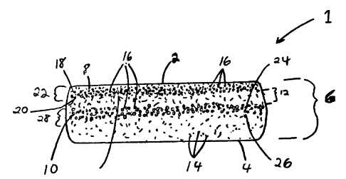
Figure 8 is a perspective view of a preferred
embodiment of an absorbent article of the invention,
more specifically this absorbent article is a sanitary
napkin. This figure illustrates one embodiment of the
positioning of densified channels 50 and the resulting
centrally located region 52.
A preferred apparatus for making the absorbent
structure of the invention is illustrated in Figure 9.
With reference to Figure 9, the absorbent element of the
present invention may be prepared according to the
following method. While any of the absorbent fibers as
previously discussed may be used to form the absorbent
element, for purposes of illustration, wood pulp fibers
are used to describe the preferred apparatus. The wood
pulp of the absorbent element is supplied in raw
material form as a compressed sheet, or pulp board 150,
that is wound on a roll. The pulp unwind 151 allows the
board to be fed into a pulp mill 152, where a high speed
hammer rotor opens the board into substantially
individual wood pulp fibers of about 2.5 mm average
length, commonly known as pulp fluff or ground wood
pulp. Air is pulled through the pulp mill and the
PPC-730
CA 02329389 2000-12-21
- 32 -
adjacent forming chamber 153 by a forming wheel vacuum
154. This air conveys the pulp fluff to a forming wheel
155 and into a mold 156. The molds 156 are cavities in
the forming wheel surface spaced around the
circumference of the forming wheel 155. The bottom of
the molds comprises a porous screen to allow the air to
be pulled through the molds, leaving the pulp fluff
deposited on the screen.
The molds are mounted on the forming wheel which
rotates clockwise. When the molds first enter the
forming chamber at position A, they are empty. In the
Initial Fiber Deposition Zone 157, 100% pulp fibers are
deposited on the bottom of the molds 156. The thickness
of pulp deposited in the Initial Fiber Deposition Zone
comprises 5% to 25% of the final thickness of the
absorbent element, and it acts as a filter to hold the
granular superabsorbent polymer powder that will be
deposited in the mold. The boundaries of the Initial
Fiber Deposition Zone 157 are formed by the left side of
the forming chamber 153 and the left side of the seal
for the first Particle Application Zone 158.
The first Particle Application Zone 158 comprises a
rotary particle applicator valve 159 that dispenses a
predetermined amount of particles into the pulp fluff in
each mold. The particles are applied in a pattern that
is phased with the molds to form the first high
PPC-730
CA 02329389 2000-12-21
- 33 -
absorbency zone. Although the first high absorbency zone
shown in this embodiment is generally rectangular, the
shape of the first high absorbency zone is not limited
to rectangular. Any shape of first high absorbency zone
may be used and one of ordinary skill in the art will
discern that varying first high absorbency zone shapes
may be desirable or even preferable for varying shapes
and types of absorbent elements.
The molds then enter an Intermediate Fiber
Deposition Zone 160 wherein additional pulp covers the
first high absorbency zone.
The second Particle Application Zone 158' is
similar to the first Particle Application Zone 158 as it
comprises a second rotary particle applicator valve 159'
that dispenses a predetermined amount of particles onto
the pulp fluff applied in each mold in the Intermediate
Fiber Deposition Zone 160. The particles are applied in
a pattern that is phased with the molds to form the
second high absorbency zone, and in this embodiment,
such that the second high absorbency zone is
substantially centered in the mold. Preferably, the
second high absorbency zone is spaced at least 3 mm
inwardly from the peripheral edges of the mold. Most
preferably, the second high absorbency zone is spaced at
least 7 mm inwardly from the peripheral edges of the
mold, and therefore, also at least 7 mm from the
PPC-730
CA 02329389 2000-12-21
- 34 -
peripheral edges of the absorbent element contained
therein. Although the second high absorbency zone shown
in this embodiment is generally rectangular, the shape
of the second high absorbency zone is not limited to
rectangular nor is it limited to the same shape as the
first high absorbency zone. Any shape of second high
absorbency zone may be used and one of ordinary skill in
the art will discern that varying second high absorbency
zone shapes may be desirable or even preferable for
varying shapes and types of absorbent elements.
The molds then enter the Final Fiber Deposition
Zone 161 wherein additional pulp covers the second high
absorbency zone thereby forming an integral absorbent
element. The molds are slightly overfilled with pulp,
and two scarfing brushes 162 are used to make the pulp
even with the top of the mold. The absorbent elements
are then vacuum transferred out of the molds onto the
Vacuum Transfer Drum 163, from which they may then be
transferred to another forming station for incorporation
into absorbent products.
Figures 10A, lOB, 11A, 11B, and 12, illustrate the
operation of the first and second Rotary Particle
Application Valves 159 and 159' in greater detail. Since
the first and second Rotary Particle Application Valves
159 and 159' are substantially identical in operation,
detailed reference will be made to the first Rotary
PPC-730
= CA 02329389 2000-12-21
- 35 -
Particle Application Valve 159 as it operates in the
first Particle Application Zone 158. It will be
understood that the second Rotary Particle Application
Valve 159' in the second Particle Application Zone 158'
will function in the same manner as the first Rotary
Particle Application Valve 159.
Figures 10A and 10B show an axial view and a side
view respectively of first Rotary Particle Application
Valve 159 in the particle application phase. In order to
achieve a precise pattern of particles on each mold 156,
first Rotary Particle Application Valve 159 is used as a
means to start and stop the flow of particles to the
molds 156. Particles are delivered to the first Rotary
Particle Application Valve 159, in the first Particle
Application Zone 158. Preferably, the particles are
delivered via a first gravimetric feeder, such as a
loss-in-weight (LIW) screw feeder 170 to accurately
control the particle weight applied to each mold 156.
The first particle supply source 172 is located outside
of the first Particle Application Zone. The discharge
end of the screw feeder 170 is located within a
stationary funnel 174 of the first Rotary Particle
Application Valve. The stationary funnel is housed
within the rotor 176 of the first Rotary Particle
Application Va1ve. The rotor 176 comprises at least one
rotor slot opening 178. The widths of the stationary
funnel 174, the rotor slot opening 178, and the
PPC-730
CA 02329389 2000-12-21
- 36-
discharge end of the screw feeder 170 are matched to the
width of the desired pattern of particles to be formed
on each mold, which determines the shape of the first
high absorbency zone. As the rotor 176 turns, and the
rotor slot opening 178 aligns with the discharge end of
the screw feeder 170, the superabsorbent polymer
particles 16 contained in the stationary funnel drop by
gravity onto the mold 156. The forming wheel vacuum 154
assists with the drawing of the particles downward onto
the mold 156. Preferably, a portion of the screen bottom
of each mold 156 is also masked such that an opening
remains having the desired pattern shape. This
selective masking of the pulp molds enhances the
accurate and precise placement of the particles within
the pulp mold. The length of the rotor slot 178 dictates
the length of the pattern of particle forming the first
high absorbency zone 8 of the absorbent element 1.
Figures 11A and 11B show an axial view and a side
view respectively of the first Rotary Particle
Application Valve 159 in the recycle phase. In Figures
11A and 11B, the forming wheel 155 is shown in a
position such that the first Rotary Particle Application
Valve 159 is located over a portion of the wheel between
two molds 156. It is desired to prevent the deposition
of particles over this portion of the wheel, since any
particles dispensed in this position are essentially
wasted and serve only to contaminate the area
PPC-730
CA 02329389 2000-12-21
- 37 -
surrounding the apparatus. The recycle phase shown in
Figures 11A and 11B prevents the problems associated
with unwanted disposition of particles by recycling the
particles. When the first Rotary Particle Application
Valve 159 is in the recycle phase as shown, the position
of the rotor 176 under the stationary funnel 174
prevents the passage of particles; i.e., the rotor slot
178 is in a closed position. Particles exiting the first
screw feeder 170 hit the inside diameter of the rotor. A
rotor vacuum port 180 in the side of the rotor opens to
the rotor inside diameter through a series of recycle
holes 182 in the rotor and pulls the particles out of
the rotor and into a recycling tube 184. As shown in
Figure 12, the particles are then conveyed by air
through the recycling tube 184 to a recycle receiver 202
that will eventually provide the particles back to the
first screw feeder 170 for reuse. Also shown in Figure
12 is a detailed view of the first particle supply
source 172, including both the virgin supply reservoir
204 and the recycle receiver 202.
Likewise, the second Rotary Particle Applicator
Valve 159' in the second particle Application Zone 158'
functions similarly. Third and fourth and more rotary
particle applicator valves may also be added in a
similar manner to produce absorbent elements with more
than two high absorbency zones separated from one
PPC-730
CA 02329389 2000-12-21
- 38 -
another throughout the thickness of the absorbent
element.
The specification and embodiments above are
presented to aid in the complete and non-limiting
understanding of the invention disclosed herein. Since
many variations and embodiments of the invention can be
made without departing from its spirit and scope, the
invention resides in the claims hereinafter appended.
PPC-730