Note: Descriptions are shown in the official language in which they were submitted.
CA 02329566 2000-12-22
Apparatus for growing thin films
The present invention relates to an apparatus according to the preamble of
claim 1
for producing thin films on the surface of a substrate by subjecting the
substrate to
alternately repeated surface reactions of vapor-phase reactants.
This kind of apparatus comprises at least one process chamber having a tightly
sealable construction, at least one into the interior of said process chamber
adaptable
reaction chamber including a reaction space of which at least a portion is
movable,
to infeecl means connected to the reaction space for feeding reactants into
the reaction
space and outfeed means connected to the reaction space for discharging excess
reactants and reaction gases from the reaction space, and at least one
substrate
adapted into said reaction space.
t5 Conventionally, thin-films are grown using vacuum evaporation deposition,
the
Molecular Beam Epitaxy (MBE) and other similar vacuum deposition methods,
different variants of the Chemical Vapor Deposition (CVD) method (including
low-
pressure and organometallic CVD and plasma-enhanced CVD) or a deposition
method of alternately repeated surface reactions called the Atomic Layer
Epitaxy
2o method, or in short, ALE or ALCVD. In addition to other process variables,
the thin
film growth rate in the MBE and CVD methods is also determined by the
concentrations of the starting material inflows. To achieve a uniform
thickness of the
layers deposited by these methods, the concentrations and rcactivities of
starting
materials must be carefully kept constant on different surface areas of the
substrate.
25 If the different starting materials are allowed to mix with each other
prior to reaching
the substrate surface as is the case in the <:VD method, for instance, a
chance of their
mutual reaction arises. Then, a risk of microparlicle formation already within
the
infeed channels of the gaseous reactants is imminent. Such microparticles
generally
have a deteriorating effect on the quality of the deposited thin film.
Therefore, the
3o possibility of premature reactions in MBE and CVD reactors, for instance,
is avoided
by heating the starting materials not earlier than at the substrate surfaces.
In addition
to heating, the desired reaction can be initiated using, e.g., a plasma
discharge or
CA 02329566 2000-12-22
other similar activating means.
In the MBE and CVD processes, the growth of thin films is primarily adjusted
by
controlling the infeed rates of starting materials impinging on the substrate.
In con-
s trast, the growth rate in the ALE process is controlled by the substrate
surface
qualities, rather than the starting material concentrations or flow variables.
The only
prerequisite in the ALE process is that the starting material is available in
sufficient
concentration for film formation on the surface of the substrate. The AL,E
method is
described, e.g., in FI patent publications 52,359 and 57,975 and in U.S.
patent
to publications 4,058,430 and 4,389,973. Furthermore, equipment constructions
suited
to implement this method are disclosed in patent publications US 5,855,680 and
FI 100,409. Apparatuses for growing thin films are also described in the
following
publications: Material Science Report 4(7) (1989), p. 261, and Tyhjiotekniikka
(Finnish publication for vacuum techniques), ISBN 951-794-422-5, pp. 253-261.
In the ALE growth method described in FI Pat. No. 57,975, the reactant atoms
or
molecules are arranged to sweep over the substrates thus impinging on their
surface
until a fully saturated molecular layer is formed thereon. Next, the excess
reactant
and the gaseous reaction products are removed from the substrates with the
help of
2o inert gas pulses passed over the substrates or, alternatively, by pumping
the reaction
space to a vacuum before the next gaseous pulse of a different reactant is
admitted.
The succession of the different gaseous reactant pulses and the diffusion
barriers
formed by the separating inert gas pulses or cycles of vacuum pumping result
in a
thin film growth controlled by the individual surface-chemical reactions of
all these
components. If necessary, the effect of the vacuum pumping cycle may be
augmented by the inert gas flow. For the function of the process, it is
irrelevant
whether the gaseous reactants or the substrates are kept in motion; it only
matters to
keep the different reactants of the successive reactions separate from each
other and
to have them sweep successively over the substrate.
Most vacuum evaporators operate on the so-called "single-shot" principle.
Hereby, a
vaporised atom or molecule can impinge on the substrate only once. Ifno
reaction
CA 02329566 2000-12-22
with the substrate surface occurs, the atom/molecule is rebound or revaporized
so as
to hit the apparatus walls or the vacuum pump undergoing condensation therein.
In
hot-walled reactors, an atom or molecule that collides with the process
chamber wall
or the substrate can undergo revaporization and, hence, repeated impingements
on
the substrate. When applied to ALE process chambers, this "multi-shot"
principle can
offer a number of benefits including improved efficiency of material
consumption.
ALE reactions operating on the "multi-shot" principle generally are designed
for the
use of a cassette unit in which a plurality of substrates can be taken
simultaneously
~o into the process chamber or, alternatively, the substrates can be placed
unmountedly
into the process space formed by the pressure vessel, whereby the process
space also
serves as the reaction chamber wherein the vapor-phase reactants are reacted
with the
substrate surface in order to grow thin film structures. If a cassette unit
designed for
holding several substrates is employed, the reaction chamber is formed in the
interior
15 of the cassette unit. Use of a cassette unit shortens the growth time per
substrate in
respect to single-substrate cycling, whereby a higher production throughput is
attained. Furthermore, a cassette unit arranged to be movable into and out
from the
process chamber can be dismantled and cleaned without interrupting the
production
flow because one cassette unit can be used in the process chamber while
another one
2o is being cleaned.
Batch processing is preferred in conventional ALE thin film processes because
of the
relatively slow production pace of the ALE method in regard to other thin film
growth techniques. Furthermore, the overall growth time per substrate of a
thin film
25 structure can be reduced in a batch process to a more competitive level.
For the same
reason, also larger substrate sues are preferred.
In the deposition of thin films, the goal is to keep the process chambers
continually
running under controlled process conditions as to the temperature, pressure
and other
so process parameters, whereby particulate matter of the ambient air and other
chemical
impurities cannot reach the substrates. Additionally, this arrangement
eliminates the
heating/cooling cycles that impair the reliability of process chambers and are
time-
CA 02329566 2000-12-22
4
consuming. Generally, a separate loading chamber is employed that is
continually
kept under a vacuum and to which the reactors are connected. Substrate loading
thereto and unloading therefrom is accomplished by taking both the process
chamber
and the loading chamber to a vacuum, after which a valve between both chambers
is
opened and a robotic arm adapted into the loading chamber removes the
processed
substrate and loads a new substrate into the process chamber. Subsequently,
the
valve is closed and the process may be started after the substrate and the
process
chamber have attained the proper process conditions. Next, the processed
substrate is
moved via another controllable valve from the loading chamber to an air lock
to pumped to a vacuum, after which the valve is closed. Subsequently, the air
lock can
he pressurized, whereby the substrate can be removed from the system via a
third
valve opening into the ambient space. The new substrate to be processed is
taken in
the same fashion via the loading chamber into the process chamber.
Currently, process apparatuses equipped with this type of a loading chamber
are
available for single substrates only and they are not suited for accommodating
heavy
substrate cassette units. Depending on the batch and substrate size, such
cassette
units may weigh up to 200 kg, whereby devices designed for their handling must
have a sturdy construction. Moreover, the lubrication of bearings and other
similar
2o components of the transfer means is problematic, because the lubricant
required
herein may affect the structure of the thin film to be grown.
The large cassette units used in conventional ALE deposition processes are
assembled outside the process apparatus, after which the process chamber is
opened
and the cassette units are transferred as assembled entities into the process
chamber.
In the process chamber, the cassette unit is heated typically for 1-4 hours,
processed
for 2-4 hours and cooled up to ten hours depending on the cassette unit size.
Furthermore, the assembly/disassembly of the cassette unit is a time-consuming
operation. The ratio of the processing time vs. the work time required for
other
operations becomes even more disadvantageous when thin films of extremely
shallow thickness (e.g., in the range I-50 nm) are to be grown, whereby the
growth
period rnay take from one minute to a few minutes. Under these circumstances,
a
CA 02329566 2000-12-22
major portion of the overall process cycle time in regard to the actual thin
film
growth period is lost in heating/cooling the reaction chamber structures,
pressurizing
the reactor, disassembling and reassembling the reaction chamber, pumping to a
vacuum and repeating the system.
It is an object of the present invention to provide an entirely novel type of
ALE
apparatus equipped with a loading chamber and suited for the use of
automatically
movable cassette units.
to The goal of the invention is achieved by equipping the process chamber with
a
separate loading chamber that can be pressurized independently from the
process
chamber and even so that the loading of the cassette unit into the process
chamber
can be carried out under a vacuum or a low-pressure inert gas atmosphere. This
kind
of loading chamber used in silicon thin-film production equipment is generally
called
t5 a platform. The loading chamber can be complemented with prehcating/cooling
stations to shorten the overall processing cycle time. Optionally, a plurality
of
process chambers can be connected each loading chamber. For moving the
cassette
unit, the reactor is provided with a transfer mechanism capable of accurately
and
sealably placing the cassette unit into its proper position in the process
chamber and
2n removing the same therefrom.
More specifically the apparatus according to the invention is characterized by
what is
stated in the characterizing part of claim 1.
25 The invention offers significant benefits.
With the help of the loading chamber, the cassette unit can be moved into the
process
chamber and out therefrom so that the process chamber is at all times kept
under
stabilized process conditions. Hence, the steps of heating, pressurizing and
pumping
3o to a vacuum need not be carried out for the entire process chamber, but
instead, for
the substrates only, thus improving the efficiency of process chamber use
vastly.
Owing to the use of the loading chamber, the interior parts of the process
chamber
CA 02329566 2000-12-22
are isolated from a direct connection to the ambient air, whereby the number
of
detrimental particles in the process chamber is reduced. The transfer
mechanism
employed in the embodiment of the invention is capable of moving relatively
heavy
cassette unit constructions and locating them accurately in a desired position
within
the process chamber. A single loading chamber can be connected to a plurality
of
process chambers adapted to produce different kinds of thin film structures,
whereby
onto the substrates may be grown a plurality of thin-film layers without the
need for
intermediate transfer of the cassette units to ambient air atmosphere, whereby
the risk
of possible contamination and the required number of thermal cycles are
reduced.
In the following, the invention will be described in greater detail with the
help of
exemplifying embodiments illustrated in the appended drawings, in which
FTG. 1 is a partially sectional view of an embodiment of the apparatus
according to
the invention; and
FTG. 2 is a layout diagram of another embodiment of the apparatus according to
the
invention.
In the context of the present invention, the term "reactant" refers to a gas
or a
vaporizable solid or liquid starting material capable of reacting with the
surface of
the substrate. The ALE method conventionally uses reactants selected from two
separate groups. The term "metallic reactants" is used of metallic compounds
which
may even be elemental metals. Suitable metallic reactants are the halogenides
of
metals including chlorides and bromides, for instance, and organometallic com-
pounds such as the thd complex compounds. As examples of metallic reactants
may
be mentioned Zn, ZnClz, Ca(thd)z, (CH3)3A1 and CpzMg. The term "nonmetallic
reactants" is used for compounds and elements capable of reacting with
metallic
compounds. The latter group is appropriately represented by water, sulfur,
hydrogen
3o sulfide and ammonia.
In the present context, the term "protective gas" is used when reference is
made to a
CA 02329566 2000-12-22
gas which is admitted into the reaction space and is capable of preventing
undesired
reacti~ms related to the reactants and, correspondingly, the substrate. Such
reactions
include e.g. the reactions of reactants and the substrate with possible
impurities. The
protective gas also serves to prevent reactions between substances of
different
,5 reactant groups in, e.g., the infeed piping. In the method according to the
invention,
the protective gas is also advantageously used as the carrier gas of the vapor-
phase
pulses of the reactants. According to a preferred embodiment, in which
reactants of
different reactant groups are admitted via separate infeed manifolds into the
reaction
space, the vapor-phase reactant pulse is admitted from one infeed channel
while the
protective gas is admitted from another infeed channel thus preventing
admitted
reactants from entering the reactant infeed channel of another reactant group.
Examples of suitable protective gases are inert gases such as nitrogen and
noble
gases, e.g., argon. The protective gas may also be an inherently reactive gas
such as
hydrogen gas selected to prevent undesirable reactions (e.g., oxidization
reactions)
15 from occurring on the substrate surface.
According to the invention, the term "reaction chamber" includes both the
reaction
space in which the substrate is located and in which the vapor-phase reactants
are
allowed to react with the substrate in order to grow thin films as well as the
gas
2o infeedloutfeed channels communicating immediately with the reaction space,
said
channels serving to admit the reactants into the reaction space (infeed
channels) or to
remove the gaseous reaction products and excess reactants of the thin-film
growth
process from the reaction space (outfeed channels). A substrate located in
this kind
of reaction chamber is subjected to alternately repeated surface reactions of
at least
z5 two different reactants used for producing a thin film. The vapor-phase
reactants are
admitted repetitively and alternatingly, each reactant being fed separately
from its
own source into the reaction chamber, where they are allowed to react with the
substrate surface for the purpose of forming a solid-state thin film product
on the
substrate. Reaction products which have not adhered onto the substrate and any
3o possible excess reactant are removed from the reaction chamber in the vapor
phase.
Herein, the term "substrate surface" is used to denote that surface of the
substrate
CA 02329566 2000-12-22
onto which the vapor-phase reactant flowing into the reaction chamber
impinges. In
practice, said surface, during the first cycle of the thin-film growing
process is
constituted by the surface of a substrate such as glass, for instance, or some
other
starting surface; during the second cycle the surface is constituted by the
layer
formed during the first cycle and comprising the solid-state reaction product
which is
deposited by the reaction between the reactants and is adhered to the
substrate, etc.
The term "process chamber" is used when reference is made to the space in
which
the thin tilrn growth process is carried out and which is isolated from its
environment
in a tightly sealable manner. The reaction chamber is located in the process
chamber
and, further, a single process chamber may incorporate a plurality of reaction
chambers.
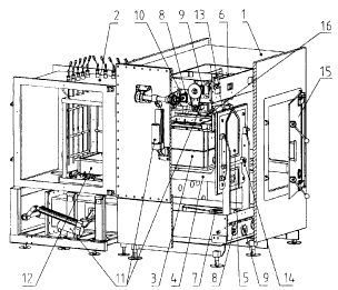
Now referring to F1G. 1, the apparatus construction illustrated therein
includes a
is Inading chamber 1, also serving as a loading gate, whose wall is partially
sectioned
in the diagram to elucidate the interior of the chamber, transfer means
adapted into
the loading chamber 1 and a cold-walled process chamber 2, whose one wall is
partially sectioned in the diagram to elucidate the interior of the chamber. A
cassette
unit 3 containing substrates and acting as the process space is shown resting
on forks
20 4 mounted ~n the door 5 separating the loading chamber 1 from the process
chamber
2. Above the cassette unit 3 is adapted a sprayhead 16 containing the reactant
infeed
channels. Into the process chamber 2 is permanently mounted a suction box 12
above
which the cassette unit 3 and the sprayhead 16 can be located and which houses
the
outfeed means of reaction gases and excess reactants. The cassette unit 3, the
25 sprayhead 16 and the suction hox l2 together form the reaction chamber.
Door .5 that also serves as the gate valve between the loading chamber l and
the
process chamber 2 is adapted movable by means of an actuator mechanism 7. A
lateral transfer mechanism 6 of the cassette unit 3 is located above the
cassette unit 3
30 and is adapted to grip the cassette unit 3 during the lifting thereof by
means of hooks.
Both the actuator mechanism 7 and the top-side lateral transfer mechanism 6 of
the
door 5 can use an eccentric cam 8 for actuating the lift movement and a ball
screw 9
CA 02329566 2000-12-22
9
for actuating the horizontal movement. One advantage of these arrangements is
a
reliably tightly sealed implementation of rotary motion feedthroughs 10. The
electrical actuators 11 of the transfer means 6, 7, 8, 9 can be located
outside the
loading chamber 1 and the process chambers 2, thus avoiding subjecting the
elec-
trical actuators 11 to breakthrough problems that may occur under a vacuum.
Moreover, this arrangement makes the maintenance of the actuators 11 easier.
T'he cassette unit 3 with the substrates placed therein, together with the
sprayhead 16
located thereabove, is transferred via the door 15 into the loading chamber 1,
after
~o which the door l5 is closed. As the steps of the ALE process are typically
earned out
at a pressure of about 0.1 - 30 mbar, the loading chamber 1 after the door 15
is
closed must be pumped to a pressure lower than the process pressure. For this
purpose, the loading chamber 1 is advantageously equipped with a separate
vacuum
pump dedicated to this task. After vacuum pumping, the door 5 separating the
loading chamber 1 from the process chamber 2 is opened with the help of the
door
actuator mechanism 7. The door 5 is arranged to move in the interior of the
loading
chamber in a direction essentially orthogonal to its seal surface. The lateral
transfer
mechanism 6 locks to the top of the cassette unit 3 by means of hooks and
transfers
the cassette unit 3 with the sprayhead 16 onto vertically movable lift means
such as
zo forks 4 mounted on that side of the door 5 facing the process chamber 2.
Subsequently, the hooks of the lateral transfer mechanism 6 are detached from
the
cassette unit 3, whereby the door 5 can he controlled to close. The cassette
unit 3
with the sprayhead 16 resting on the forks 4 can be lowered onto a suction box
12 at
a distance of about 10 -20 mm from the closed position of the door 5, whereby
the
z5 forks 4 mounted on the door 5 will be released before the end of the
downward
motion as the cassette unit 3 remains resting on the suction box 12. This
arrangement
relieves the door 5 from additional load at its closing instant, whereby it
can easier
mate with its seat surface and thus impose a uniform linear pressure on the
seal 13 as
required for an efficient seal. The seating step can be eased by a pivoting
mount 14
30 of the door.
After the processing steps are completed, the cassette unit 3 with the above-
lying
CA 02329566 2000-12-22
1~
sprayhead 16 is lifted off from above the suction box 12 by means of the forks
4.
Next, the door 5 is opened and the cassette unit 3 is moved on the forks 4
into the
loading chamber 1. With the help of its hooks, the lateral transfer mechanism
6 grips
the cassette unit 3 at its top and transfers the cassette unit 3 with the
above-lying
sprayhcad 16 from the forks 4 to in front of the door 15 of the loading
chamber 1.
Alter the door 5 is closed, the loading chamber 1 can be pressurized and the
cassette
unit 3 removed from the loading chamber 1. Removal of the cassette unit 3 from
the
lading chamber 1 and loading of a new cassette unit into the loading chamber 1
can
be performed using, e.g., a carriage equipped with a fork lift mechanism.
to
'Thermal expansion movements of the suction box 12 and the cassette unit 3 may
impose thermal stresses on the suction box 12 if it is supported to the
process
chamber 2 by its edges, for instance. The magnitude of such then al expansion
movements may mount up to several millimeters. These dimensional changes may
~5 complicate some process steps, e.g., the positioning of the cassette unit 3
in the
process chamber 2 during the automated unload/load steps. Hence, the suction
box
12 is advantageously supported to the wall structures of the process chamber 2
so
that the center of the support point coincides at least substantially with the
center
pOlllt of the suction box 12, whereby the suction box 12 has a greater degree
of
2o freedom to expand outward from its support point and the positioning
accuracy of the
cassette unit 3 is improved.
In the embodiment shown in FIG. 2, the loading chamber 1 is made wider in its
lateral dimension so as to provide the loading chamber 1 with additional
cassette
2s unload sites by extending the reach of the lateral transfer mechanism 6.
Thus, a
single loading chamber 1 can be connected to a plurality of process chambers
2.
Herein, the process chambers Z may be adapted to produce, e.g., different
types of
thin-film structures or to run the different steps of a given thin-film growth
process.
The use of the expanded loading chamber 1 offers a shorter processing time per
3o substrate and other salient benefits.
1n addition to those described above, the invention may have alternative
CA 02329566 2000-12-22
11
embodiments.
A single process chamber 2 may be adapted to house a plurality of reaction
chambers. Furthermore, the loading chamber 1 may be complemented with an
s intermediate station serving to heat the cassette unit 3 prior to its
transfer into the
process chamber 2 and/or to cool the cassette unit 3 prior to its transfer of
out from
loading chamber 1, whereby the throughput capacity of the process chamber 2 is
improved. Moreover, the cassette unit 3 can be advantageously transferred from
the
ambient air atmosphere into loading chambers 1 having a plurality of unload
to positions for cassette units 3 and respectively out therefrom via a
separate
pressurizing chamber, whereby there is no need for pressurizing the large-
volume
loading chamber 1 in conjunction with the transfer of the cassette unit 3.
In lieu of the door 5, the scaling between the process chamber 2 and the
loading
~ 5 chamber 1 can be implemented using a gate valve, for instance.
Furthermore, the cas-
sette unit 3 acting as the reaction space need not have a construction that
must be
moved as an entity. The interior of the cassette unit 3 may be provided, e.g.,
with a
holder into which the substrates are placed and in which they are moved via
the
loading chamber 1 into the pxocess chamber 2 and then away from the process
2o chamber 2.