Note: Descriptions are shown in the official language in which they were submitted.
CA 02329625 2000-12-27
Title
WATERPROOF BOAT-LIKE SHELL FOR FOOTWEAR MADE BY
CEMENT LASTING PROCESS
Scope of the Invention
This invention relates to footwear and, particularly, boots having a
preferably waterproof boat-like shell.
Background of the Invention
Footwear and particularly boots are known which have a one-piece boat-
like shell comprising the sole, vamp and heel counter injection-molded as from
rubber or
plastic compounds and to which an upper may be attached. The one-piece boat-
like shell
effectively provides a waterproof lower-most portion of the boot which extends
across
the top of the toes upwardly to at least partially overlie the ball of a
user's foot, preferably
to the instep and rearwardly to about the heel. Such boots have been well
received in the
marketplace. However, they suffer the disadvantage that the same material is
used for the
sole as for the vamp and the heel and must be formed by the same process. A
disadvantage of such boots as appreciated by the present inventor is that they
do not
permit the advantageous use of different materials for the sole, vamp and heel
counter
and do not permit use of different processes for manufacture and treating of
the materials
for these various portions of the boot.
Summary of the Invention
To at least partially overcome these disadvantages of previously known
devices, the present invention provides a construction for a footwear boat-
like shell
having an injection-molded sole of preferably lightweight rubber formed by
injection-
molding and to which an upper including a water impermeable vamp and heel
counter
formed to an insole board by a cement lasting process.
CA 02329625 2005-08-19
An object of the present invention is to provide a substitute for a
conventional one-piece boat-like shell for footwear.
Another object is to provide a waterproof construction for footwear
formed by a cement lasting.
Another object is to provide a boat-like shell for footwear formed with an
injection-molded sole and a vamp and a heel counter of plastic, preferably
vinyl, material
carrying decorative markings thereon.
Another objective is to provide an improved method for construction of a
waterproof boat-like shell for footwear.
In one aspect, the present invention provides an article of footwear
comprising a sole, a vamp, a heel counter and an insole board,
the sole comprising a water impermeable unitary member formed by
injection molding,
the vamp and heel counter each having an interior surface and an exterior
surface with the exterior surface formed by a sheet of water impermeable
plastic material,
the insole board having a lower surface and a perimeter thereabout,
the vamp and heel counter secured to the insole board to extend upwardly
from the perimeter of the insole board and with flange portions of each of the
vamp and
heel counter folded to extend under the insole board, to an inner peripheral
edge of the
flange portions and with the interior surfaces of the flange portions secured
to the lower
surface of the insole board,
a continuous layer of water impermeable sealant over the exterior surfaces
of the flange portions under the insole board and over the lower surface of
the insole
board inwardly of the flange portions to seal the lower surface of the insole
board and
junctures between the insole board and the inner peripheral edge of the flange
portions
against water penetration,
the sole having a continuous circumferential upper rim in engagement
with and encircling the vamp and counter,
a continuous joint of water impermeable adhesive joining the upper rim of
2
CA 02329625 2005-08-19
the sole to the exterior surfaces of the vamp and heel counter continuously
circumferentially about the rim,
the vamp having a toe portion extending over the toes and upper portion of
the foot to enclose toes and an upper portion of a foot received in the
footwear rearwardly
from the toes at least rearward to above a ball of the foot.
In another aspect, preferably, the continuous layer of water impermeable
sealant covers the exterior surfaces of the vamp and heel counter laterally
from the
exterior surfaces of the flange portion under the insole board to the upper
rim.
Brief Description of the Drawings
Further aspects and advantages of the present invention will become
apparent from the following description taken together with the accompanying
drawings
in which:
Figure 1 is a pictorial view of a first preferred embodiment of a boot in
accordance with the present invention;
Figure 2 is a schematic exploded side view showing selected components
of the boot of Figure 1;
Figure 3 is a side view of an assembly of the insole board, vamp and heel
counter;
Figure 4 is a cross-sectional view along line 4-4' of Figure 3;
Figure 5 is a cross-sectional view along line 5-5' in Figure 3;
Figure 6 is a top view of the assembly shown in Figure 3;
Figure 7 is a bottom view of the assembly shown in Figure 3, however,
with the filler 14 shown in place;
Figure 8 is a schematic cross-section of a segment of the vamp shown in
Figure 4;
Figure 9 is a side view of an assembly of a boat-like shell; and
Figure 10 is a cross-sectional view along line X-X' in Figure 9.
2a
CA 02329625 2000-12-27
Detailed Description of the Drawings
Reference is made first to Figure 1 which shows an assembled boot 10 in
accordance with the first embodiment of the present invention.
Figure 2 shows in a schematic exploded view various components of the
boot. These components include a sole 12, a filler 14, an insole board 16, a
vamp 18, a
heel counter 20 and an upper generally indicated 22.
The vamp 18 comprises a sheet member which is formed into a generally
U-shape as seen in Figure 6 extending from one rear edge 30 to a second rear
edge 32 on
opposite sides. An upper edge 34 is of a U-shape and defines a major portion
of an
opening to receive a user's foot therethrough. As best seen in Figures 4, 5
and 7, a lower
edge 36 of the vamp 18 wraps underneath the lower surface 38 of the insole
board 16 and
is secured thereto. The vamp 18 thus has a lasting allowance flange 40 which
is provided
underneath the insole board 16 and extends about the periphery of the insole
board from
one rear edge 30 to the other rear edge 32 of the vamp.
The vamp is shown to have a toe portion 42 which extends from the front
toe 44 of the vamp over an upper portion of a foot of a user to the upper edge
34. At the
forwardmost portion of the upper edge 34, the vamp preferably extends
sufficiently high
so that the toe portion 42 extends rearwardly to provide continuous cover and
preferably
waterproofing over the toe at least rearward of a ball of a foot and
preferably rearward to
proximate where an instep commences.
The heel counter 20 comprises a sheet material which, as seen in Figure 6,
extends in a general U-shape from a front edge 46 on one side to a front edge
48 on the
other side. The heel counter 20 extends upwardly to an upper edge 50 and
downwardly
to a lower edge 52. The lower edge 52 is underneath the insole board 16 and a
lasting
allowance flange 54 is provided as part of the heel counter which extends
underneath the
insole board 16 and is bonded thereto.
On each side of the assembly shown in Figure 3, the vamp 18 is secured to
the heel counter 20 as along a stitched line shown at 56 in Figure 3. This
stitched line
CA 02329625 2005-08-19
preferably is formed by stitching the materials together and applying sealants
preferably
to an inside of the stitching sufficient to waterproof the seam and its
stitching.
Each of the vamp 18 and heel counter 20 are preferably formed with a
sheet-like material forming their exterior surface, which sheet-like material
can
permanently carry surface contours such as deformations therein or ridges
thereon which
provide a pleasing, decorative appearance. In this regard, as best seen in
Figure 5, the
vamp is provided with a series of shallow grooves therein which provide a
pleasing
appearance. In the particular embodiment shown in the grooves include a groove
58
which delineates an imitation toe counter portion 60. Further, a plurality of
decorative
grooves 62 extend radially inwardly from the groove 58 to the upper edge 34 to
provide a
decorative appearance.
In a somewhat similar manner, the exterior surface of the heel counter 20
carries an oval depression 63 and raised lettering therein representing a
trade mark of the
boot manufacture provide the manner of grooves and/or a relief permanently
formed in
the exterior surface of the heel counter.
Each of the vamp 18 and heel counter 20 preferably has an outer sheet
which comprises a plastic material. The plastic material may be selected from
vinyl,
urethane, rubber and other plastic materials and composites and copolymers
thereof. The
plastic material preferably is waterproof in the sense of preventing water and
moisture to
pass therethrough and not retaining water therein. Preferred of such materials
is vinyl.
The surface of the outer sheet, preferably vinyl material, is preferably
treated by being
passed through a roller which removes a previously existing surface from the
vinyl
material so as to provide an altered surface, preferably an embossed surface.
The surface
is preferably selected to have a surface similar to that of leather or suede-
like material
with slight indentations and giving a slightly distressed look similar to that
of suede or
leather. Preferably the surface is not shiny. The outer sheet preferably must
be selected
such that after treating the surface, the material is waterproof.
Grooves 58 and 62 are preferably permanently imprinted using a high
frequency welding technique under which high frequency sound waves are
directed into
4
CA 02329625 2005-08-19
the vinyl at a time when the vinyl is being deformed by a printing plate or
roller so as to
permanently deform the outer vinyl layer with the groove, surface detail
etchings,
patterns, relief, embroidering and the like. As well, decorative features such
as false
stitching lines or joining seams may be formed. Other decorative features can
be
provided such as raised areas and ribs and the like.
Each of the vamp 18 and heel counter 20 preferably comprise a laminate
having a preferred outer layer of vinyl material. Preferably, inner layers of
reinforcement
and/or insulation materials may be provided secured as an inner layer of the
vamp and
heel counter. Figure 8 shows an enlarged cross-section of the vamp showing an
outer
layer of vinyl material 68 and an inner layer of backing material 70.
In accordance with the present invention, the vamp 18 and heel counter 20
are formed to have preferred grooves and surface texture. In a cement lasting
process,
the insole board 16 is placed on a last and the vamp 18 and heel counter 20
are secured to
the insole board 16 as by adhering the flanges 40 and 54 to the under surface
38 of the
insole board 16. Subsequently, an assembly including the insole board 16, vamp
18 and
heel counter 20 are placed on the sole 12 sandwiching the filler 14
therebetween.
The insole board 16 and filler 14 are preferably secured to the sole 12 by a
double bonding process in which a layer of water impermeable sealing and/or
adhesive
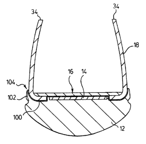
compound is provided as a continuous layer schematically shown as 100 in
Figure 10
over the entire lower surface of the lasting allowance flanges 40 and 54 of
the vamp and
counter and over the entirety of the lower surface 38 of the insole board 16
so as, for
example, to provide a impermeable seal against water passing through the
composite
structure formed by the insole board 16, vamp 18 and heel counter 20. In
addition,
additional cementing is provided as a continuous secondary seal area, bead or
joint 102
about the periphery of the sole 12 where an upper rim 104 of the sole 12
merges with the
vamp 18 and heel counter 20 circumferentially about the sole 12 as seen in
Figure 10.
Figure 9 shows a resultant assembly comprising a boat-like shell 72 which
may be produced as a composite of the sole 12, filler 14, insole board 16,
vamp 18 and
heel counter 20. While the insole board 16, vamp 18 and heel counter 20 are
joined by a
CA 02329625 2000-12-27
cement lasting process by the use of a water impermeable injected rubber sole
12, a water
impermeable vinyl sheeting for each of the vamp 18 and heel counter 20 and
with
providing for water impermeable joining of the vamp 18 to the heel counter 20
and water
impermeable joining of the vamp 18 and heel counter 20 to the sole 12 as well
as the
preferred undercoating of the flange portions of the vamp and heel counter and
the under
surfaces of the insole board 16 with waterproof surface coating adhesives, the
boat-like
shell comprises effectively a waterproof vessel made by the cement lasting
process. This
waterproof boat-like shell may preferably comprise a lower portion of a
footwear which
may adopt and have varying uppers which may be laced or slide on or may be of
varying
heights. The boat-like shell will be used with a shaft or collar which extends
upwardly as
in a manner of the boot shown or may be very shallow as in the manner of
providing a
slipper or the like.
The novel selection of the particular elements of construction, namely, the
relatively lightweight injection-molded sole, the vinyl vamp and vinyl heel
counter
carrying a decorative surface and decorative grooves therein provide for a
novel
construction which is relatively inexpensive to manufacture yet can be
perfectly
waterproof and has the appearance of the well known accepted one-piece boat-
like shells.
While the vamp 18 is shown as one piece as is preferred to reduce seams
which must be waterproofed, the vamp 18 may comprise a number of pieces of
sheet
material as with a separate toe counter or pieces between.
Many modifications and variations of the invention will now occur to
persons skilled in the art. For a definition of the invention, reference is
made to the
appended claims.
6