Note: Descriptions are shown in the official language in which they were submitted.
CA 02330137 2000-10-23
1
METHOD FOR SEPARATING A C4 HYDROCARBON MIXTURE
The present invention relates to a process for separating a
C4-hydrocarbon mixture essentially containing 1,3-butadiene,
butenes, butanes and other C4-hydrocarbons into at least 4
fractions,
a) the fraction (a) essentially comprising 1,3-butadiene,
b) the fraction (b) essentially comprising butenes,
c) the fraction (c) essentially comprising butanes and
d) one or more fractions (d) essentially comprising [lacuna] the
other C4-hydrocarbons,
by extractive distillation by means of
N-methyl-2-pyrrolidinone or an aqueous solution of
N-methyl-2-pyrrolidinone (NMP),
wherein
1. the gaseous C4-hydrocarbon mixture is first brought into
contact with NMP in an extraction zone (I), the 1,3-butadiene
and the other C4-hydrocarbons being essentially completely
absorbed by the NMP but the butenes and butanes remaining
essentially in the gas phase;
2. the unabsorbed butenes and butanes (gas stream bc) and the
extraction solution formed in step 1 (extraction solution ad)
are removed from the extraction zone (I);
3. the extraction solution (ad) is transferred to a desorption
zone (I) at a lower pressure and/or higher temperature than
the extraction zone (I) and 1,3-butadiene is desorbed from
the extraction solution (ad), the main part of the other
C4-hydrocarbons remaining in the liquid phase;
4. the extraction solution formed in stage 3 (extraction
solution d) and the desorbed 1,3-butadiene (fraction a) are
removed separately from the desorption zone (I) and, if
CA 02330137 2000-10-23
t
' 0050/48979
2
required, a part of the fraction (a) is returned to the
extraction zone I;
5. the extraction solution (d) is transferred to a second
desorption zone (II) at a lower pressure and/or higher
temperature than the desorption zone (I) and having a
pressure and/or temperature gradient, and the other
C4-hydrocarbons and the 1,3-butadiene still remaining therein
are fractionally desorbed from the extraction solution (d) as
at least two separate fractions (d), with the content of the
other C4-hydrocarbons being at least 10 times higher in at
least one of the fractions (fractions d) than in the
extraction solution (d), based on the content of all
C4-hydrocarbons, and the content of the other C4-hydrocarbons
being correspondingly lower in at least one of the fractions
(fractions dR) than in the fractions (d), based on the
content of all CQ-hydrocarbons,
6. the NMP, formed in the desorption zone (II) and essentially
free of C4-hydrocarbons, and the fractions (d) and (dR) are
removed separately from the desorption zone II, and one or
more fractions (dR) are returned to the desorption zone (I),
7. the gas stream (bc) is first brought into contact with the
NMP formed in step 6 in an extraction zone (II), the butenes
being essentially completely absorbed by the NMP but the
butanes remaining essentially in the gas phase;
8. the unabsorbed butanes (fraction c) and the extraction
solution formed in step 1 (extraction solution b) are removed
from the extraction zone (II);
9. the extraction solution (b) is transferred to a desorption
zone (III) at a lower pressure and/or higher temperature than
the extraction zone (II) and the butenes are desorbed from
the extraction solution (b);
10. the NMP, formed in step 9 and essentially free of
C4-hydrocarbons, and the desorbed butenes (fraction b) are
removed from the desorption zone (III);
11. the NMP formed in step 9 is recycled to one of the extraction
zones.
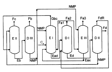
This process is shown schematically in Fig. 1.
CA 02330137 2000-10-23
0050/48979
3
A process for separating 1,3-butadiene from a C4-hydrocarbon
mixture is disclosed, for example, in DE-A-2724365. Briefly, a
butane/butene mixed fraction, a 1,3-butadiene fraction and a
fraction which contains the other C4-hydrocarbons are obtained in
this process from a C4-hydrocarbon mixture which contains butanes,
butenes, 1,3-butadiene and other C4-hydrocarbons, by extractive
distillation with NMP as absorbent over various absorption and
desorption stages. In the entire process, the NMP required passes
through a closed circulation. NMP which no longer contains any
C4-hydrocarbons (unladen NMP) is first laden with the
C4-hydrocarbon mixture at the beginning of a cycle, passes through
the various absorption and desorption stages until, at the end of
a cycle, unladen NMP is provided by completely desorbing the
C4-hydrocarbons. The process is distinguished by the fact that the
individual stages are particularly advantageously coupled via
indirect heat exchange processes.
The separation of 1,3-butadiene and 2-butenes into separate
fractions and the separation of 1,3-butadiene and acetylenes into
separate fractions from C4-hydrocarbon mixtures have been
described by V. A. Gorshkov et al. in the publication The Soviet
Chemical Industry, No. 11, November 1971.
EP-A-141356 likewise relates to the separation of a 1,3-butadiene
fraction from a C4-hydrocarbon mixture by means of extractive
distillation using NMP. The use of columns in which absorption
and desorption zone are integrated in a single column in each
case make this process particularly economical.
EP-A-5788 discloses a process for separating a 1,3-butadiene
fraction and a butyne fraction from a C4-hydrocarbon mixture by
means of extractive distillation using NMP.
EP-A-9630 relates to a process for separately removing styrene
and 1,3-butadiene from a mixture which otherwise contains
C4-hydrocarbons, the styrene first being separated from the
mixture by distillation and 1,3-butadiene being separated from
the remaining mixture by means of extractive distillation.
US 5242550 discloses the separation of a butene/butane mixture by
means of extractive distillation using NMP as absorbent.
It is an object of the present invention to provide a process
which permits the separation of a C4-hydrocarbon mixture into a
butane fraction, butene fraction, 1,3-butadiene fraction and a
fraction which contains the other C4-hydrocarbons in a
particularly efficient and economical manner. In particular, the
CA 02330137 2000-10-23
' ' 0050/48979
4
required quantities of energy and the capital costs should be
particularly low in this process.
We have found that this object is achieved by the process
5 described at the outset.
The process can be applied to C4-hydrocarbon mixtures which
contain 1,3-butadiene, butenes, butanes and other C4-hydrocarbons
plus very small amounts of C3- and C5-hydrocarbon impurities.
Such C4-hydrocarbon mixtures are obtained, for example, as C4
fractions in the production of ethylene and/or propylene by
thermal cleavage of a petroleum fraction, for example of
liquefied petroleum gas (LPG), naphtha, gas oil or the like as
hydrocarbon fraction. Furthermore, such C4 fractions are obtained
in the catalytic dehydrogenation of n-butane and/or n-butene. The
C4 fractions obtain [sic], as a rule, butanes, n-butene,
isobutene, 1,2 butadiene, vinylacetylene, ethylacetylene and
1,2-butadiene [sic) and may contain small amounts of
C5-hydrocarbons, the 1,3-butadiene content being in general from
10 to 80, preferably from 20 to 70, in particular from 30 to 60,
percent by weight while the content of vinylacetylenes,
ethylacetylene and 1,2-butadiene (referred to below as other
hydrocarbons) together in the C4 fractions generally does not
exceed 5 percent by weight.
The novel process can advantageously be employed in particular to
those C4-hydrocarbon mixtures which contain
- from 10 to 80~ by weight of 1,3-butadiene;
- from 10 to 60~ by weight of butenes;
- from 5 to 40~ by weight of butanes;
- from 0.1 to 5~ by weight of other C4-hydrocarbons and
- from 0 to at most 5~ by weight of C3- and C5-hydrocarbons.
The n-methyl-2-pyrrolidinone or its aqueous solution employed as
selective solvent (N-methyl-2-pyrrolidinone and its aqueous
solution abbreviated to "NMP" for short hereinafter) is generally
a conventional industrial product which may contain up to 15g by
weight of water.
CA 02330137 2000-10-23
0050/48979
a 5
The extraction zones are preferably in the form of columns
through which the gas streams are passed countercurrently to the
NMP.
In step 1, the C4-hydrocarbon mixture to be separated is first fed
in gaseous form with NMP into an extraction zone (I) and brought
into contact with one another there, the 1,3-butadiene and the
other C4-hydrocarbons being essentially completely absorbed by the
NMP but the butenes and butanes remaining essentially in the gas
phase. In the NMP and C4-hydrocarbon mixture fed in, the ratio of
NMP to C4-hydrocarbon mixture is from 5 . 1 to 20 : 1 in the
extraction zone (I).
The generally known extraction methods are suitable for this
extraction step.
From the extraction zone (I), in general a gas stream which
[lacuna] in particular unabsorbed butanes and butenes and, if
C3- and C5-hydrocarbons are present as impurity in the CQ mixture,
also propane, propene and propadiene plus traces of
C5-hydrocarbons (gas stream bc) is removed at the top of column
and the extraction solution (extraction solution ad) is removed
from the bottom of the column.
The extraction solution (ad) contains in general only from 0 to
2% by weight of butenes and butanes, plus, if present, propyne
and/or almost the total amount of C5-hydrocarbons.
The gas stream (bc) contains, in addition to the butenes and
butanes, in general only from 0 to 1% by weight of the
1,3-butadiene originally present in the C4-hydrocarbon mixture and
of the other C4-hydrocarbons.
The extraction zone (I) is generally in the form of a scrubbing
column with plates, dumped packings or structured packings as
internals. These preferably have from 40 to 80 theoretical
plates. The column pressure depends on the temperature of the
cooling medium (well water, river water, sea water, refrigerants
such as liquid propylene, liquid ammonia or brine). It is between
2 and 6 bar, preferably 4.5 bar. The temperature profile in the
extraction zone is determined by the temperature of the NMP. It
is advantageous to lower the temperature profile by partial
condensation of the fraction (bc) because the separation
efficiency is improved at lower temperature. A typical value for
the condensation is 20%. This results in a temperature of from 40
to 60 C at the top of the column.
CA 02330137 2000-10-23
0050/48979
6
For the desorption of the 1,3-butadiene from the extraction
solution (ad), the latter is transferred to a desorption zone (I)
at a lower pressure and/or higher temperature than the extraction
zone (I) and 1,3-butadiene (1,3-butadiene fraction a) is desorbed
from the extraction solution (ad), the main part of the other
C4-hydrocarbons, propyne and C5-hydrocarbons remaining in the
liquid phase.
Preferably, the pressure in the desorption zone (I) is the same
as that in the extraction zone (I) and the temperature is from 20
to 25°C higher than in the extraction zone (I).
The 1,3-butadiene fraction (a) removed from the desorption zone
(I) usually has a purity of from 95 to 99% by weight.
The extraction solution (d) formed by desorption of 1,3-butadiene
in the desorption zone (I) is then removed from the desorption
zone (I) and transferred to a second desorption zone (II) at a
lower pressure and/or higher temperature than the desorption zone
(I). During transfer of the extraction solution (d) from
desorption zone (I) to (II) it advantageously passes through a
heat exchanger zone in which a part of the hydrocarbons in the
extraction solution (d) evaporates, and this gas stream is
directly fed back into the bottom of desorption zone (I).
Pressure and temperature are chosen so that virtually all
C4-hydrocarbons still remaining in the NMP are desorbed; they are
in general 1.5 bar and 150°C.
In desorption zone II there is fractional desorption from the
extraction solution (d) of 1,3-butadiene still present therein
and of the other C4-hydrocarbons plus, where appropriate, [lacuna]
and C5-hydrocarbons still present therein as at least two separate
fractions (d), with the content of other C4-hydrocarbons being at
least 10 times, in general from 10 to 100 times, preferably from
20 to 80 times, higher in at least one of the fractions (fraction
d) than in the extraction solution (d), based on the content of
all C4-hydrocarbons, and the content of the other C4-hydrocarbons
being lower in at least one of the fractions (fractions dR) than
in the fractions (d), based on the content of all C4-hydrocarbons.
The hydrocarbons in the extraction solution (d) are preferably
fractionated in the desorption zone (II) into a fraction (d) and
a fraction (dR), where fraction (d) preferably comprises
essentially at least 20~ by weight, particularly preferably from
20 to 40~ by weight, of other C4-hydrocarbons and otherwise
butadiene, and fraction (dR) comprises essentially more than 80~
CA 02330137 2000-10-23
0050/48979
7
by weight, particularly preferably from 85 to 95% by weight, of
butadiene and otherwise other C4-hydrocarbons.
The NMP formed in the desorption zone (II) and essentially free
of C4-hydrocarbons, and fractions (d) and (dR) are removed
separately from the desorption zone II, and one or more of the
fractions (dR) are returned to the desorption zone (I), e.g. to
the bottom of the scrubbing column.
The pressure gradient in this case is preferably overcome by
means of a compressor. The fraction (d) is normally treated
countercurrently with water (condensate) in order to absorb most
of the NMP present therein.
In general, the ratio by weight of the fractions returned to the
desorption zone (I) to those removed from the system is from 20:1
to 80:1.
The desorption zone (II) consists in general of a main column
with a side column. Both are designed as scrubbing columns. The
main column generally contains packings because the low pressure
drop thereof has particularly beneficial effects here. The main
column should have from 10 to 15 theoretical plates. The side
column generally has 10 practical plates. The pressure is
generally from 1.5 to 1.6 bar; the temperature at the bottom of
the main column is from 140 to 150 C and at the top thereof is
from 80 to 100°C. While the fractions (d) are removed as
sidestream preferably at from 130 to 140°C, the fractions (dR) are
normally taken off overhead.
If a 1,3-butadiene fraction having a particularly high purity is
desired, the following procedure is preferably adopted:
- The 1,3-butadiene fraction (a) which is removed from the
desorption zone (I) is divided into two part streams of
fraction (al) and (a2), and fraction (al) is returned to the
extraction zone I (is preferably passed to the bottom of the
extraction column I) and fraction (a2) is again brought into
contact, in an extraction zone (III), with NMP which was
recovered from the desorption zone (II) or (III), a part of
the fraction (a2) and the predominant part of other
CQ-hydrocarbons still contained as impurity in the fraction
(a2) being absorbed by the NMP (extraction solution ax).
CA 02330137 2000-10-23
0050/48979
15
8
- The unabsorbed part of the fraction (a2) (fraction a3) is
removed separately from the extraction zone, and the
extraction solution (ax) is returned to the extraction zone
(I).
This variant is illustrated in Fig. 2.
The ratio by weight of NMP to 1,3-butadiene fraction (a)
generally corresponds to from 1:3 to 1:7, depending on the
composition of the initial C4 mixture and the specifications for
fraction (a3).
The ratio of the material streams of fractions (al) and (a2) is
normally from 1:1 to 4:1.
The 1,3-butadiene fraction (a3) still contains impurities in
particular in the form of C3- and C5-hydrocarbons and
1,2-butadiene. These impurities are in general subsequently
removed in two conventional distillation columns.
Regarding the design of the extraction column and the parameters
of pressure and temperature, the same applies in general terms to
the extraction zone (III) as to the extraction zone (I). The
ratio of NMP fed in to the crude butadiene fraction (a2)
corresponds to from 1:3 to 1:7.
The unabsorbed 1,3-butadiene and the 1,3-butadiene taken off from
the extraction zone (III) normally has a purity of more than 98%
by weight.
The gas stream (bc), optionally with the addition of the external
added stream (gas stream Zbc is first brought into contact, in an
extraction zone (II), with the NMP recovered in the desorption
zone (II), the butenes being essentially completely absorbed by
the NMP but the butanes remaining essentially in the gas phase.
The extraction zone (II) is in general in the form of a scrubbing
column with plates, dumped packings or structured packings as
internals. These must have from 30 to 70 theoretical plates in
order to achieve a sufficiently good separation effect. The
pressure in the extraction zone (II) is chosen so that the gas
stream (bc) is able to pass from the extraction zone (I) without
further technical assistance into the extraction zone (II). It
also depends on the cooling medium available for condensing the
fraction (c). A typical value for the pressure is 4.0 bar,
provided water is used for cooling.
CA 02330137 2000-10-23
0050/48979
9
The scrubbing column is advantageously equipped in the top of the
column with a back-wash zone which comprises, for example, 4
theoretical plates. This back-wash zone serves for recovering the
NMP present in the gas phase by means of back-flow of liquid
hydrocarbon, for which purpose fraction (c) has previously been
condensed. It is possible at the same time to influence thereby
the temperature profile in the extraction zone (III). It also
applies in this case, as already mentioned in extraction zone
(I), that a lower temperature promotes the separation efficiency.
Typical temperatures at the top of the column are between 35 and
45°C.
The ratio by weight of NMP to gas stream (bc), including gas
stream Zbc where appropriate, in the feed to extraction zone (II)
is from 10:1 to 20:1, depending on the specifications for
fractions (b) and (c) and the composition of the initial C4
mixture and of the added stream Zbc.
In the extraction zone (II), a gaseous butane fraction (fraction
c) and an extraction solution (b) containing the butene fraction
(fraction b) are formed. If the extractive distillation is
carried out as described above, a fraction (b) which is
contaminated with up to 5~ by weight of butanes and a fraction
(c) which is contaminated with up to 15~ by weight of butenes are
obtained.
The extraction solution (b) is transferred to a desorption zone
(III) at a lower pressure and/or higher temperature than the
extraction zone (II), the butenes being desorbed from the
extraction solution (b). The desorption of the butenes and of any
other C4-hydrocarbons contained therein as impurity can in
principle be carried out similarly to the desorption of the other
C4-hydrocarbons in the desorption zone (II).
The desorption zone (III) may be, for example, in the form of a
scrubbing column which has from 5 to 15, preferably from 8 to 10,
theoretical plates and a back-wash zone with, for example, 4
theoretical plates. This back-wash zone serves for recovering the
NMP present in the gas phase by means of a back-flow of liquid
hydrocarbon, for which purpose the fraction (b) has previously
been condensed. It is advantageous to provide packing beds as
internals. The pressure at the top of the column is generally 1.5
and [sic] 1.6 bar. The temperature in the bottom of the column is
generally from 130 to 150°C.
CA 02330137 2000-10-23
0050/48979
The NMP recovered in the desorption zone (III) is returned to the
extraction zones (I), (II) and/or (III).
An additional advantage accrues when the NMP recovered in the
5 desorption zone (III) is fed back only into the extraction zones
(I) and (II), and the NMP recovered in the desorption zone (II)
is essentially fed back into the extraction zone (III).
The advantage derives from the fact that the removal of
10 butenes/butanes from a C4-hydrocarbon mixture using NMP takes
place more easily than the separation of a mixture of butenes and
butanes into two high-purity butene and butane fractions.
Moreover a single solvent circulation is maintained.
In contrast to the extraction zone (III), which requires high-
purity degassed NMP, the quality of the NMP for the extraction
zones (I) and (II) does not need to be so high. This signifies a
gain economically in that the degree of degassing of the NMP, and
thus the consumption of external steam for desorbing hydrocarbons
in the desorption zone (III), does not need to be so high. In
contrast to the NMP from the desorption zone (II), where from 0
to 10 ppm by weight of C4-hydrocarbons are desired, it is
perfectly possible for the NMP from the desorption zone (III) to
have 1000 or more ppm by weight. This does not impair the purity
of product fractions (b) and (c). On the other hand, however, a
content of hydrocarbons reduces the boiling point of the solvent.
Since the heat content of the NMP from the desorption zone (III)
is utilized, however, for reasons of economy, it is not possible
to continue reducing the boiling point by increasing the residual
content of hydrocarbons indefinitely. The bottom temperatures of
from 130 to 150 C indicated previously result for these reasons.
At a bottom temperature of 138°C, the resulting residual content
of hydrocarbons is about 800 ppm by weight.
The novel process can be carried out particularly economically if
the heat of the NMP which is obtained by boiling up the
extraction solutions (b) and (d) is fed to the desorption zone
(I), (II) and/or (III) by indirect heat exchange in a heat
exchange zone, and the desorption is effected in these desorption
zones by increasing the temperature in the desorption zone (I)
relative to that in the extraction zone (I), and increasing the
temperature in the desorption zone (II) relative to that in the
desorption zone (I) and increasing the temperature in the
desorption zone (III) relative to that in the extraction zone
(II).
CA 02330137 2000-10-23
0050/48979
11
The separation of the fraction (a) (butadiene) from the
C4-hydrocarbon mixture is preferably carried out as described in
DE-A-2724365. This part of the process is particularly preferably
carried out as described in Fig. 3.
According to this process variant, the following procedure is
adopted:
The extractive distillation is carried out in more than one
column, in general in two columns which together have more than
100 practical trays. When using two columns, the absorption stage
situated above the point at which the C4-hydrocarbon mixture is
fed into the extractive distillation zone is advantageously
located in the first column and the concentration stage situated
below the feed point of the hydrocarbon mixture is advantageously
located in the second column, i.e. the feed point for the
hydrocarbon mixture is at the top of the second column or
preferably at the bottom of the first column. Preferably, no
compression stage is located between absorption stage and
concentration stage, and instead the pressure conditions
maintained within the extractive distillation zone are those
automatically established in the extractive distillation zone in
the absence of compression and/or pressure reduction stages
within the extractive distillation zone, so that the pressure at
the bottom of the extractive distillation zone corresponds at
least to the pressure at the top of the extractive distillation
zone, in line with the usual pressure loss. As a rule, the
pressure difference between top and bottom of the extractive
distillation zone is from 0.1 to 3, preferably from 0.2 to 2,
bar.
In general, pressures of from 1 to 9, preferably from 2 to 8, in
particular from 3 to 7, bar are used in the extractive
distillation zone. The pressures in the lower third of the
extractive distillation zone, i.e. in the region which is
occupied by the lower trays of the extractive distillation zone,
which correspond to about a third of the total number of trays of
the extractive distillation zone, are as a rule from 1.5 to 9,
preferably from 2.5 to 8, in particular from 3.5 to 7, bar.
The extract taken off from the extractive distillation zones is
first brought to a higher pressure than the pressure in the
extraction distillation zone.
This can be effected, for example, by means of a liquid pump. In
general, this pressure increase is effected essentially
isothermally, i.e. the only temperature changes which occur, for
CA 02330137 2000-10-23
0050/48979
12
example a temperature increase up to 1~C, are those which are
caused by the measure leading to the pressure increase, for
example the pumping process. In general, the extract is brought
to pressures which are from 1 to 20, preferably from 2 to 18, in
particular from 3 to 15, bar above the pressure in the extractive
distillation zone, in particular above the pressure in the lower
third of the extractive distillation zone.
The extract under increased pressure is then heated in a heat
exchange zone by indirect heat exchange with the selective
solvent obtained as a bottom product from the solvent recovery
zone. The selective solvent is recycled to the extractive
distillation zone after the heat exchange. As a result of the
heat exchange with the selective solvent, the temperature of the
extract is generally increased by from 5 to 80~C, preferably 10 to
70~C, in particular from 15 to 60~C.
The heated extract is then let down by flash evaporation to a
pressure which corresponds at least to the pressure in the
extractive distillation zone, preferably at least to the pressure
in the lower third of the extractive distillation zone, and is
higher than the pressure in the downstream solvent recovery zone.
It is critical for the pressure reduction that the vapor fraction
of the extract, which fraction forms in the flash evaporation,
can be returned to the extractive distillation zone without a
compression stage. Accordingly, as a rule the pressure is let
down in the flash evaporation to pressures which are from 0.05 to
2.0, preferably from 0.1 to 1, bar above the pressure at the feed
point of the vapor fraction of the extract into the extractive
distillation zone. The flash evaporation is carried out, for
example, in an apparatus comprising a pressure reduction valve on
an adiabatic evaporator, if required a phase separation vessel
being provided downstream for better separation of the vapor and
liquid phases forming in the flash evaporation.
The combination of heat exchange zone for the heat exchange
between the extract from the extractive distillation zone and the
selective solvent recycled from the solvent recovery zone with
the downstream flash evaporation can be used in one stage.
However, it is also possible to use more than one such
combination, for example from 2 to 4, preferably 2 or 3, such
combinations, advantageously connected in series. By using more
than one of these heat exchange/flash evaporation stages and
recycling the part-streams thus obtained to different feed points
of the extractive distillation zone, the required separation
efficiency of the extractive distillation and the dimensions of
the extractive distillation column can be reduced. It is also
CA 02330137 2000-10-23
0050/48979
13
possible to connect a further heat exchange zone between the last
flash evaporation zone and the solvent recovery zone.
That vapor fraction of the extract which forms in the flash
evaporation zone or zones and generally comprises from 20 to 80,
preferably from 40 to 70, % by weight of the hydrocarbons in the
extract is returned to the extractive distillation zone. In
general, the returned vapor phase is passed into the lower third
of the extractive distillation zone, preferably at the bottom of
the extractive distillation zone, for example at a point which is
located roughly at the height of the lowermost column tray. In
the stepwise flash evaporation, vapor fractions contained in the
individual stages can be returned, separately or after their
combination, to the extractive distillation zone.
The liquid phase of the extract from the extractive distillation
zone, which phase remains after flash evaporation, is fed to a
solvent recovery zone which is operated at a lower pressure than
the pressure in the flash evaporation zone. The remaining liquid
extract phase is let down to the lower pressure in the solvent
recovery zone, advantageously by means of an intermediate
pressure reduction valve. In general, the pressure in the solvent
recovery zone is from 0.1 to 8, preferably from 0.5 to 7, in
particular from 1 to 6, bar lower than the pressure in the flash
evaporation zone or zones. The solvent recovery zone may be
operated, for example, as a gas expulsion zone or as a solvent
stripper. In general, heat is supplied to the solvent recovery
zone, for example via an indirect heat exchanger using steam
(reboiler).
The NMP obtained as a bottom product of the solvent recovery zone
and freed from the hydrocarbons is returned to the extraction
stages (I) and (III) via the heat exchange zone in which the heat
exchange with the extract from the extractive distillation zone
takes place.
The product which is obtained from the solvent recovery zone
contains the hydrocarbons and is in general taken off as a top
stream or as a top and side stream, passes partly or if necessary
completely initially through a compression stage and is fed to
the extractive distillation zone after the compression. In the
compression zone, the hydrocarbon stream is compressed to a
pressure which corresponds at least to the pressure in the
extractive distillation zone. In general, the hydrocarbon stream
is compressed to pressures which are from 0.05 to 2, preferably
from 0.1 to 1, bar above the pressure at the feed point of the
CA 02330137 2000-10-23
0050/48979
14
vapor fraction of the extract into the extractive distillation
zone.
Fig 3 is a schematic diagram of an embodiment of the preferred
variant. In this embodiment, 2 extractive distillation zones are
connected in series. The first extractive distillation zone is
formed by column 1 and the upper tapered column section 2, while
the second extractive distillation zone is formed by column 4 and
the lower column section 3. The NMP is fed to the upper part of
column 1 through line 5 and to the upper part of column 4 through
line 6. A C4-hydrocarbon mixture is fed to the bottom of column 1
via line 7.
The columns 2/3 and 4 are also directly connected. A gaseous part
stream is removed from the column 2 and washed countercurrently
with solvent through line 6.
At the top of the column 1, a refined product which consists
essentially of butenes and butanes is taken off through line 8.
At the top of the column 4, an essentially pure 1,3-butadiene is
taken off through line 9.
A gas stream containing essentially the other hydrocarbons and
other impurities is removed via the side take-off of the column
10 through line 11.
The pressure in the column section 3 is about 5 bar. The extract
taken off via line 12 is brought to 15 bar by a liquid pump 13
and then heated at from 70?C [sic) to 125?C [sic] in heat
exchanger 14 by means of the NMP taken off from gas expulsion
zone 10 via line 24 and essentially free of C4-hydrocarbons. The
heated extract is then passed through pressure reduction valve 15
and let down to a pressure slightly above 5 bar. While the
gaseous phase formed in the phase separation tank 16 is
immediately returned through line 22 and 23 to the column 3, the
liquid phase, obtained after the flash evaporation, of the
extract is fed through line 17 to another pressure reduction
valve 18 where the pressure falls to the level of pressure in the
column 10, normally 1.5 bar.
At the top of column 10, a hydrocarbon stream is taken off
through line 19 and, after compression in the compressor 20, also
fed through line 23 to the bottom of the column 3. It is
important, for safety reasons, in this connection that the gas
stream 19 is cooled by heat exchange (not depicted in Fig. 3)
before entering the compressor 20 so that the temperature of the
CA 02330137 2000-10-23
0050/48979
gas stream after emergence from the compressor does not exceed
110°C. The gas stream is normally cooled to 45°C.
The NMP which is virtually free of C4-hydrocarbons and is taken
5 off through line 24 and cooled in the heat exchanger 14 is fed
through line 25 to the heat exchanger 2. It then passes through
another heat exchanger (not depicted in Fig. 3) in which the
temperature of the solvent is adjusted to 38°C. The amount of
solvent arriving through line 26 is then divided into two part
10 streams: line 6 leads to the column 4, while line 27 terminates
in the additional extractive distillation zone (III) for
separating butenes and butanes. The solvent returns from there
through line 5.
15 In order to simplify the drawings, all the abovementioned
back-wash zones with the flows of liquid hydrocarbons back to
columns 1 and 4 have also been omitted. The abovementioned side
column on the main column 10 is also absent from Fig. 3.
Example
Compared with Fig. 3, the diagram of the process in the example
is considerably more extensive (Fig. 4), even though all the
pumps have been omitted from the figure in this case too. On the
25 other hand, all the heat exchangers are detailed besides the
columns because they are crucially involved in the economics of
the process. Likewise, all the phase separators have been
included in the diagram. The number assignment system is likewise
evident from Fig. 4.
The extraction zone (I) and the desorption zone (I) are concealed
behind column 120. Extraction zone (III) is column 130. The
desorption zone (II) is represented by the two columns 140 and
150. Extraction zone (II) is the column 100 and desorption zone
(III) is column 110. In addition, the two final distillation
columns 160 and 170, in which the crude butadiene is finally
brought up to specification, have been included, because they
belong to the overall process.
The process has 3 incoming streams:
Stream 10: Added stream Zbc, containing butenes and butanes
Stream 40: C4 feed
Stream 69: Condensate addition to reduce the NMP loss
CA 02330137 2000-10-23
0050/48979
16
Composition [% by weight] and quantity [kg/h] of stream 10:
n-Butane 26.0
i-Butane 9.5
n-Butene 42.0
trans-2-Butene 13.0
cis-2-Butene 9.5
Quantity = 4200.
Composition [% by weight] and quantity [kg/h] of stream 40:
Propane 0.1
Propene 0.1
15Propadiene 0.05
Propyne 0.15
n-Butane 7.3
i-Butane 4.0
n-Butene 14.0
20i-Butene 24.6
trans-2-Butene 4.5
cis-2-Butene 3.5
1,3-Butadiene 40.0
1,2-Butadiene 0.45
25Ethylacetylene 0.2
Vinylacetylene 0.75
i-Pentane 0.1
3-Methyl-2-butene 0.1
2-Methyl-2-butene 0.1
30
Quantity = 15,000.
Quantity for stream 69 [kg/h]:
35 Quantity = 1100.
Solvent required for the 3 extraction zones [kg/h] and
composition thereof [% by weight] . (HC = hydrocarbons)
40 (IExtr. zone) stream 42 = 165,000 withNMP91.63
water 8.29
Total HC 0.08
Extr. zone (III) stream 46 = 35,000 with NMP 91.7
45 Water 8.3
Total HC 1 ppm by wt.
CA 02330137 2000-10-23
0050/48979
17
Extr. zone (II) stream 12 = 100,000 with NMP 91.63
Water 8.29
Total HC 0.08
Stream 57 = 165,000 with NMP 91.7
Water 8.3
Total HC 1 ppm by wt.
Temperature: generally 38°C
In the following detailed description of the columns, the plate
numbers are generally counted from the top of the column.
Operating conditions for column 100:
Number of theoretical plates - 4 + 50 (including back-wash
zone)
HC back-flow to plate - 1
Solvent feed to plate = 5
HC feed to plate - 42
Added stream Zbc to plate - 42
Pressure at plate 1 - 4.0 bar
Temperature at plate 1 - 38.5°C
HC back-flow quantity - 5000 kg/h
Operating conditions for column 110:
Number of theoretical plates - 4 + 9 (including back-wash
zone)
HC back-flow to plate - 1
Extract feed to plate - 5
Pressure at plate 1 - 1.526 bar
Temperature at plate 1 - 6.7°C
HC back-flow quantity - 5000 kg/h
Energy required - 10,361 kW
Operating conditions for column 120:
Number of theoretical plates - 25 + 23 + 7 (in 2 columns)
HC back-flow to plate - 1
Solvent feed to plate - 1
HC take-off at plate - 49(to the extraction zone II)
HC feed to plate - 26
Pressure at plate 1 - 4.5 bar
CA 02330137 2000-10-23
0050/48979
18
Temperature at plate 1 - 41.5°C
HC back-flow quantity - 2094 kg/h
Operating conditions for column 130:
Number of theoretical plates - 4 + 30 (including back-wash
zone)
HC back-flow to plate - 1
Solvent feed to plate - 5
Pressure at plate 1 - 5.0 bar
Temperature at plate 1 - 45.3°C
HC back-flow quantity - 2120 kg/h
Operating conditions for column 140:
Number of theoretical plates - 10
Extract feed to plate - 1
HC take-off at plate - 6 (to column 150)
Pressure at plate 1 - 1.52 bar
Temperature at plate 1 - 104.6°C
Temperature at plate 10 - 146.1°C
HC back-flow quantity - 2120 kg/h
Energy required - 6773 kW
Operating conditions for column 150:
Number of theoretical plates - 2
water feed to plate - 1
Extract feed to plate - 1
Pressure at plate 1 - 1.52 bar
Temperature at plate 1 - 108°C
Operating conditions for column 160:
Number of theoretical plates - 46
HC back-flow to plate - 1
Extract feed to plate - 16
Pressure at plate 1 - 7 bar
Temperature at plate 1 - 46.6°C
HC back-flow quantity - 6130 kg/h
Energy required - 761 kw
Operating conditions for column 170:
Number of theoretical plates - 45
HC back-flow to plate - 1
Extract feed to plate - 23
CA 02330137 2000-10-23
0050/48979
19
Pressure at plate 1 - 4.2 bar
Temperature at plate 1 - 39.3°C
HC back-flow quantity - 11197 kg/h
Energy required - 1671 kW
The individual process steps are as follows:
The normally liquid C4 hydrocarbon mixture (stream 40) is
vaporized in the heat exchanger 240 and enters the extraction
zone (I) as vapor, approximately in the middle of column 120.
Solvent is passed via stream 42 countercurrently to the ascending
gases. This results in two new streams: a gaseous product (stream
43) containing essentially the major quantity of propane,
propene, propadiene, the butanes and the butenes, and an extract
(stream 53) containing the hydrocarbons dissolved in the solvent,
comprising 1,3-butadiene and the other hydrocarbons, including
the C5-hydrocarbons. The 1,3-butadiene content, an important
specification quantity for the separation requirement of the
exraction zone (I), is below 100 ppm by weight.
To lower the temperature profile in the column 120, 20% by weight
of the gas stream 43 are condensed in the heat exchanger 230.
A side stream leaves the column 120 via stream 51 and is washed
countercurrently with solvent (stream 46) in the extraction zone
(II), which is column 130. To lower the temperature profile and,
at the same time, to reduce the NMP loss, the column has a
black-flow of liquid hydrocarbons (stream 50). The solvent
quantity (stream 46) is adjusted so that the specifications
relating to ethylacetylene and vinylacetylene for the later pure
1,3-butadiene are met. The decanter 320 incorporated in the top
circulation serves for partial removal of water from the crude
butadiene.
The extract from the extraction zone (I), which is stream 53,
passes through a heat exchanger 255 and is then partially
desorbed under pressure in the flash tank 410, resulting in two
streams: a gaseous portion (stream 59) which is immediately
recycled via stream 67 to the column 120, and a liquid portion
(stream 60). The temperature of the stream 60, which is still
under the elevated flash pressure in the flash tank 410, is
raised by 5 C in another heat exchanger 260, before it is let
down by reducing the pressure in the column 140.
The extract, stream 61, is almost completely desorbed from the
C4-hydrocarbons in column 140 by input of external energy. The
resulting gas, stream 62, is cooled in the heat exchanger 265 to
CA 02330137 2000-10-23
0050/48979
the abovementioned 45 C and divided in the flash tank 420 into a
very small portion of liquid phase (stream 66) and the main part
of gas phase (stream 64). The gas stream 64 is compressed in the
compressor 500 and, after combining with the streams 59 and 66,
5 returned as stream 67 to the lower part of the column 120.
A gas stream 68 is removed from column 140 approximately in the
middle. Beside hydrocarbons, it contains water. This gas stream
is washed countercurrently with condensate in the column 150, and
10 the gaseous product (stream 70) is cooled in heat exchanger 270
and, after division into a gas phase and liquid phase (streams 72
and 73), discharged as product. The NMP content in stream 70 is
about 160 ppm by weight, which signifies an NMP loss of 0.19 kg/h
at this point.
The route taken by the almost completely desorbed solvent from
the column 140 passes successively through the heat exchangers
255 (heating of the extract from column 120), 250 (reboiler for
column 170), 240 (vaporization of the C4-hydrocarbon mixture) and
235 (final solvent cooler to adjust the solvent temperature). It
thus passes completely through the extraction zones (I) and (III)
and the desorption zones (I) and (II).
The top product from column 120 (stream 45) and the added stream
Zbc (stream 11) are fed into the lower third of the extraction
zone (II), i.e. column 100. The gases are passed together with
the gas stream resulting after heat exchange in the heat
exchanger 215 and subsequent flash decompression in the flash
tank 400 countercurrently to the solvent (streams 12 and 57).
This results in a high-purity butane fraction (stream 13) with
only 0.43 by weight of butenes. Like the top product from column
130, the gas stream 13 is also condensed (heat exchanger 200) and
then partly freed of water in the decanter 300 before it is
returned as liquid hydrocarbon back-flow (stream 16) to column
100 or is discharged as butane fraction (c), i.e. stream 17, as
product.
The extract, which has already been heated by heat exchange, from
the extraction zone (II), i.e. stream 20, is fed, after renewed
indirect heat exchange in the heat exchanger 220 and after
pressure reduction, to the desorption zone (III), i.e. column
110. The extract is very substantially freed of the
C4-hydrocarbons therein by input of external heat. The butene
fraction (b) thus resulting, stream 23, is likewise of high
purity and contains only 1.85 by weight of butanes. After
condensation in the heat exchanger 225 and partial removal of
water in the decanter 225, the butene fraction is partly fed in
CA 02330137 2000-10-23
0050/48979
21
liquid form as back-flow into column 110 (stream 26) and partly
discharged as product (stream 27).
The heat exchanger 225 requires a refrigerant because of the low
condensation temperature of the butene fraction. It is not
possible to increase the pressure level in column 110: on the one
hand, the bottom temperature of column 110 would exceed the limit
of 150 C, which would be equivalent to impermissible thermal
stress on the solvent and, on the other hand, the desorption of
the hydrocarbons would be impeded, which could be compensated
only by additional input of external energy.
The solvent desorbed in the column 110 passess successively
through the heat exchangers 220 (extract preheating), 215
(raising the temperature of the extract for the purpose of the
pressure flash), 210 (vaporizer of the added stream 10) and 205
(final cooler for adjusting the solvent temperature). Because of
the variety of tasks, certain temperature levels are preset, for
which reason the hydrocarbon content of stream 28 cannot be
indefinitely high. In the exemplary case, the concentration is
800 ppm by weight. This means that it also passes completely
through the absorption and desorption zones (III).
There only remains the area with the distillation columns 160 and
170 for final adjustment of the specifications of the
1,3-butadiene fraction (a). The crude butadiene (stream 80) is
fed into the upper third of column 160. The gaseous top product
(stream 81) is condensed and, after partial removal of water in a
decanter 330, both recycled as liquid hydrocarbon back-flow
(stream 84) to column 160, and discharged as product (stream 83).
It should be noted that stream 81 must not exceed a certain
propyne concentration for safety reasons. This limiting
concentration is pressure-dependent. Its value is 50% by volume
at a top pressure of 7 bar.
The almost anhydrous bottom discharge from the column 160 is fed
into column 170 approximately in the middle. The mixture is
fractionated therein to a high-purity 1,3-butadiene fraction
(stream 89) and a bottom product (stream 91), with stream 91
representing a mixture mainly of the hydrocarbons cis-2-butene,
1,3-butadiene, 1,2-butadiene and C5-hydrocarbons. The
1,3-butadiene yield can be influenced by the preset 1,3-butadiene
concentration. This is 25% by weight in the present example. The
product specification of fraction (a), i.e. the pure butadiene,
is as follows:
1,3-Butadiene = 99.6% by weight
CA 02330137 2000-10-23
0050/48979
22
Total butenes = 0.4~ by weight
Propyne - 10 ppm by weight
1,2-Butadiene = 50 ppm by weight
Total C4-acetylenes < 5 ppm by weight
Total CS-HC < 5 ppm by weight
In conclusion, the amounts of energy [kW] exchanged for
condensers and heat exchangers are listed below:
Heat exchanger 200 . 785
Heat exchanger 205 . 8991
Heat exchanger 210 . 482
Heat exchanger 215 . 3127
Heat exchanger 220 . 4000
Heat exchanger 225 . 1679
Heat exchanger 230 .
230
Heat exchanger 235 .
2945
Heat exchanger 240 .
1772
Heat exchanger 245 .
857
Heat exchanger 250 .
1671
Heat exchanger 255 .
7264
Heat exchanger 260 .
744
Heat exchanger 265 .
1729
Heat exchanger 270 .
572
Heat exchanger 275 .
693
Heat exchanger 280 .
1757
35
45