Note: Descriptions are shown in the official language in which they were submitted.
CA 02330194 2001-01-04
1
A POLE FOR AN ELECTRICAL CIRCUIT BREAKER, EQUIPPED WITH A
WIDE ARC EXTINGUISHING CHAMBER
BACKGROUND OF THE INVENTION
The invention relates to an arc extinguishing chamber of a low-voltage, high-
current
circuit breaker. For such circuit breakers, a particular difficulty is
encountered when a
eurrent is required to be broken in a relatively high voltage, about 600 Volts
rms single-
phase or 1000 Volts rms three-phase, with a fairly low intensity of about 5 to
10 times the
rated current of the circuit breaker.
The document EP 0,306,382 describes a multipole circuit breaker with a molded
insulating
case meeting this requirement, housing an operating mechanism coupled to a
switching bar
so as to perform opening and closing of all the poles of the circuit breaker.
Each pole
comprises a stationary contact means, a movable contact means and an arc
extinguishing
chamber. The stationary contact means comprise a fixed conducting current
input strip
supported by the back-plate of the case, stationary main contacts and a
stationary arcing
contact. The movable contact means comprise a fixed conducting current input
strip also
supported by the back-plate of the case, and a contact system having a
plurality of identical
main contacts arranged in two series of the same number on each side of a
movable arcing
contact extending longitudinally along the center axis of the pole, the length
of the
movable arcing contact being greater than the length of the movable main
contacts. The arc
extinguishing chamber is arranged above the first strip and comprises a stack
of separators
formed by metal arc deionization plates, each plate having a V-shaped notch. A
pair of
CA 02330194 2001-01-04
2
arcing horns, one lower and one upper, are located on each side of the stack
of plates of the
extinguishing chamber. The lower arcing horn is fixedly secured to the top
face of the first
strip, with an insulating shield arranged between these two elements, by means
of three
screws which ensure flow of the current between the arcing horn and the strip.
The three
screws are arranged at the apexes of an isosceles triangle, one of the screws
being arranged
along the center axis of the pole near to an edge of the insulating shield and
of a wall for
outlet of the breaking gases to the outside, and the other two screws being
located near to
the stationary main contacts. The width of the lower arcing horn decreases in
the direction
of migration of the arc towards the center screw, and the other two screws are
located on
i0 each side of the stationary arcing contact and near to the corresponding
stationary main
contacts. When opening of the contacts takes place, the arc arises in the
arcing contact
separation zone situated along the center axis of the pole and subsequently
develops in the
center zone of the chamber. The arc migrates to the center screw which
stabilizes the arc
root. At the end of opening travel, the distance between the arcing contacts
becomes
greater than the distance between the main contacts, causing a new breakdown
of the arc at
the level of the main contacts on one of the sides of the chamber. The arc
then develops on
a second different path along one of the sides of the chamber, recentering
progressively
and encountering along its path cold surfaces where efficient absorption
fostering
extinguishing of the arc takes place.
In such a device, a large part of the chamber is used for extinguishing the
arc. However, it
is observed that one of the sides of the chamber remains largely unused, as
after
breakdown of the arc, the arc only develops on one of the sides of the
chamber. The depth
of the chamber, i.e. its longitudinal dimension between the entrance of the
chamber and the
CA 02330194 2001-01-04
3
gas outlet wall, must be sufficient to cope with the volume of energy exchange
necessary
for arc extinguishing. It is however desirable, for a circuit breaker of given
performances,
that the depth of the chamber be reduced, while keeping the same width, which
is a
dimension imposed in practice by fitters' standards of user.
The document FR 2,604,026 furthermore describes a circuit breaker wherein the
lower
arcing horn broadens out from its front part near the contacts to its rear
part near the back-
plate of the arc extinguishing chamber. The broadened rear part constitutes a
collecting
part of smaller surface than the cross-section of an arc root for an arc
formed with a
t o constant electrical current density corresponding to the rated breakdown
current. The
objective here is to direct the arc onto the collecting part and to stabilize
it there. The
stabilized arc then develops essentially in the center part of the chamber.
Such a
configuration is only efficient if the longitudinal dimension of the chamber,
i.e. its depth
between the stationary contact zone and the rear wall of the chamber
performing removal
of the gases is large. The width of the chamber can be reduced as it is not
used for arc
extinguishing.
OBJECT OF THE INVENTION
2o The object of the invention is to improve the performances of a multipole
low-voltage,
high-current circuit breaker in particular a circuit breaker having to be
suitable for breaking
a rated current greater than 1000 amps rms, at high voltage of about 600 Volts
in rms value
per phase. Its object is notably to reduce the volume of the chamber necessary
to guarantee
breaking of a current at high voltage, by reducing the depth of the chamber
for a given
CA 02330194 2001-01-04
4
width. Its object is more precisely to use the volume of the chamber to the
full when the
chamber is wide and of small depth and/or reduced height.
According to the invention, this objective is achieved by means of a pole for
an electrical
circuit breaker comprising a case and an operating mechanism able to switch
from a closed
position to an open position, said pole comprising:
- a stationary contact means made of conducting material comprising a contact
zone,
- a movable contact means comprising one or more contact fingers made of
conducting material, the movable contact means being able to be coupled to
said mechanism and to switch from a closed position in which the contact
finger or fingers are in contact with the contact zone of the stationary
contact
means to an open position where the two contact means are separated,
- an arc extinguishing chamber comprising:
- two parallel side flanges made of insulating material situated at
equal distance from a geometric longitudinal mid-plane of the
chamber, the longitudinal mid-plane thus bounding two geometric
lateral half-spaces each containing one of the side flanges,
- a rear wall comprising one or more gas outlet orifices,
- separators formed by metal plates extending from one of the side
flanges to the other, appreciably perpendicularly to the longitudinal
mid-plane,
- a front opening situated near to the contact zone of the stationary
contact means and facing the rear wall,
CA 02330194 2001-01-04
- a lower arcing horn made of conducting material, electrically
connected to the stationary contact means, comprising:
- a rear part situated near to the rear wall and comprising an
edge,
5 - an intermediate part joining the contact zone and the rear part,
- a back-plate made of insulating material.
- an upper arcing horn made of conducting material, the separators
being situated between the lower arcing horn and the upper arcing
horn,
lo wherein:
- the rear part has a width, measured parallel to an axis perpendicular to the
longitudinal mid-plane, which is greater than the width of the intermediate
part
measured parallel to the same axis,
- in each of the lateral half-spaces, the rear part of the arcing horn has at
least
one point situated with respect to the side flange situated in the half-space
involved at a distance which is smaller than a quarter of the distance between
the two side flanges,
- the distance between the rear part and each of the side flanges is smaller
than
half the distance between each of the side flanges and the mid-plane,
- the back-plate comprises a periphery made of gas-generating material
interposed between the edge of the rear part and the side flanges.
With a device of this type, after a test involving breaking of a current less
than 10 times the
rated current with an AC voltage exceeding 600 Volts in single-phase rms
value, it is
CA 02330194 2001-01-04
6
observed that the lower arcing horn is solicited to the same extent on the two
most lateral
parts of the rear end zone. This makes it possible to affirm, although the
theoretical bases
of the explanation are still not very precise, that the two lateral parts of
the chamber have
contributed in very close proportions to absorption of the energy given off by
the arc, and
therefore to extinguishing of the arc. In fact it is difficult to say whether
the traces
observed are due to the existence of two arcs developing simultaneously in the
chamber or
whether they are due to a high-speed lateral oscillation of the arc from one
side of the rear
end zone of the arcing horn to the other. This arrangement does nevertheless
enable the
available width of the chamber to be used to the full, and therefore breaking
of a high
lo voltage arc, above 600 Volts rms for the phase involved, to be achieved
with a chamber of
small depth.
The invention finds a particularly effective application in terms of volume
reduction if, in
each part of the chamber bounded by the longitudinal mid-plane, said point is
also situated
with respect to the rear wall at a distance which is smaller than a quarter of
the distance
between each of the side flanges. This then assures that the arc will use the
volume of
material constituted by the separators to the full.
The invention applies preferably to a pole of relatively large width, in
particular a pole
wherein the distance between the contact zone of the stationary contact means
and the rear
wall of the chamber is smaller than the distance between the side flanges of
the chamber. It
also applies to a pole wherein the lower arcing horn has a length, measured in
the
longitudinal mid-plane, which is smaller than the largest width of the rear
part of the arcing
horn measured along an axis perpendicular to the longitudinal mid-plane.
CA 02330194 2001-01-04
7
The metal plates of the separators preferably have a front edge comprising a
dissymmetric
notch directed towards one or the other of the side flanges.
Preferably the periphery protrudes out towards the inside of the chamber with
respect to
the rear part of the arcing horn or is flush with the rear part of the arcing
horn. The
protruding periphery enables a considerable gas removal to be achieved, which
contributes
greatly to creating the effect sought for of development of two parallel arcs
or of an arc
oscillating from side to side in the two lateral parts of the chamber.
According to one embodiment of the invention, it is considered that:
- each lateral half-space comprises a part of the separators, this part of the
separators having a geometric barycenter,
- in each lateral half-space, the distance between the first end zone and the
side
flange contained in the half-space is smaller than the distance between the
barycenter situated in the same half-space and said side flange.
BRIEF DESCRIPTION OF THE DRAWINGS
Other advantages and features of the invention will become more clearly
apparent from the
following description of different embodiments of the invention given as non-
restrictive
examples only and represented in the accompanying drawings in which:
CA 02330194 2001-01-04
8
- figure 1 represents a view of a pole of a switchgear apparatus according to
a first
embodiment of the invention, in cross-section along a longitudinal mid-plane
of an arc
extinguishing chamber of this pole;
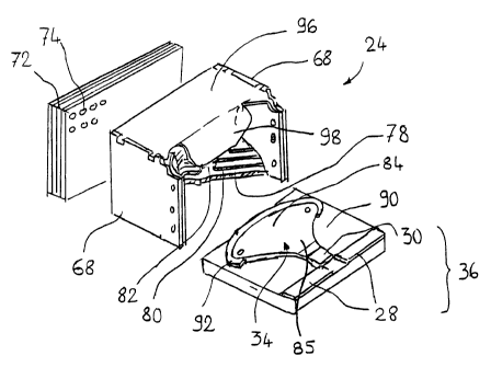
- figure 2 represents an exploded perspective view of a part of the pole of
figure 1,
showing in particular the arc extinguishing chamber;
- figure 3 represents a top view of the pole of figure 1;
- figure 4 represents a view of a pole of a switchgear apparatus according to
a second
embodiment of the invention, in cross-section along a longitudinal mid-plane
of an arc
extinguishing chamber of this pole;
-0 - figure 5 represents an exploded perspective view of a part of the pole of
figure 4,
showing in particular the arc extinguishing chamber;
- figure 6 represents a top view of the pole of figure 4.
DETAILED DESCRIPTION OF THE PREFERRED EMBODIMENTS
With reference to figures 1 to 3, a low-voltage multipole power circuit
breaker 10
comprises an insulating case 12 housing an operating mechanism 14 of known
type,
equipped with a transverse switching bar 16 common to all the poles, turning
in bearings
arranged in the case 12. Each pole comprises a stationary contact means 20, a
movable
contact means 22 and an arc extinguishing chamber 24 situated near to the
stationary
contact means 20.
The stationary contact means 20 comprise a current input strip 26 mounted on
the back-
plate of the case 12, partly under the arc extinguishing chamber 24. The
stationary contact
CA 02330194 2001-01-04
9
means 20 comprise in addition two main contact blocks 28 (figure 2) fixed
directly to the
current input strip 26 and a central arcing contact 30. The arcing contact 30
is fixed to the
current input strip 26 in an intermediate zone between the blocks 28 and the
chamber 24.
The arcing contact 30 is extended towards the inside of the chamber 24 by a
conducting
lower arcing horn 34 described in detail further on. The current input strip
26, blocks 28,
arcing contact 30 and arcing horn 34 are made of various conducting materials
and are at
the same potential. The arcing contact 30 and blocks 28 together form a
contact zone 36
designed to perform the electrical contact with the movable contact means 22.
The movable contact means 22 comprise for their part a fixed conducting
current input
strip 40, a support cage 42 pivotally mounted around an axis 44 fixed with
respect to the
case 12, and a plurality of main contact fingers 46 (figure 3) placed on each
side of a
central arcing contact finger 48. The contact fingers 46, 48 pivot around a
common
geometric axis 50, fixed with respect to the cage 42, and are biased towards
the stationary
contact means 20 by contact pressure springs 52. A connecting rod 54 performs
the
coupling between the cage 42 of the movable contact means 22 and a crank 56 of
the
switching bar 16 of the mechanism 14. Each main finger 46 comprises a contact
pad 58
designed to perform the contact with the corresponding contact block 28 of the
stationary
contact means 20 when the apparatus is in the closed position represented in
figure 1, and a
spigot 60 protruding out beyond the contact pad in the direction of the arc
extinguishing
chamber 24. The arcing contact finger for its part has a movable arcing
contact 62
designed to perform contact with the stationary arcing contact 30 of the
stationary contact
means 20 when the apparatus is in the closed position represented in figure 1,
and a spigot
64 protruding out beyond the contact pad in the direction of the arc
extinguishing chamber
CA 02330194 2001-01-04
24 with an identical shape to that of the spigots 60. The contact fingers 46,
48 are
electrically connected to the current input strip 40 by means of braids 49.
The arc extinguishing chamber 24 comprises two side flanges 68 made of
insulating
5 material, which are parallel to the cross-sectional plane of figure 1 and
situated at equal
distance on each side of the latter, so that the cross-sectional plane
constitutes a geometric
longitudinal mid-plane 70 of the chamber 24 and of the pole. A rear wall 72
for outlet of
the gases is arranged at the rear of the chamber, perpendicularly to the side
flanges 68.
This wall 72 comprises one or more orifices 74 for outlet of the breaking
gases. A front
10 opening 76 is arranged near to the contact zone 36, opposite from the rear
wall 72.
Separators 78 formed by flat metal plates extend perpendicularly to the
longitudinal mid-
plane 70 from the front opening 76 to the rear wall 72. The separators 78 are
arranged at a
distance from one another so as to leave the possibility of a gas flow between
the front
opening 76 and the rear wall 72. The separators are supported laterally by the
side flanges
68. Each plate 78 has an front electric arc pick-up edge 80 which presents a
curved
concave U-shape or V-shape approximately in the plane of the plate, with a
narrower
dissymmetric notch 82. The separators 78 are stacked so that the notches 82
are alternately
on one and the other lateral side of the chamber 24.
The lower arcing horn 34, designed to receive the arc root when the arc
extends from the
stationary arcing contact 30 towards the inside of the chamber 24, comprises a
rear part 84
situated inside the chamber, and an intermediate part 85 joining the rear part
to the
stationary arcing contact 30. The width of the rear part 84, i.e. its largest
dimension
measured along an axis perpendicular to the longitudinal mid-plane 70 of the
chamber, is
CA 02330194 2001-01-04
11
large whereas the intermediate part 85 constitutes a narrower section. The
rear part 84
presents two lateral surfaces forming receiving areas 86 for the root of an
electric arc
developing in the chamber 24.
The distance between the receiving area 86 and the side flange situated in the
same half-
space bounded by the longitudinal mid-plane 70 is smaller than half the
distance between
the flange 68 and the mid-plane 70, and therefore smaller than a quarter of
the width of the
chamber measured between the flanges 68. The receiving areas 86 are also
relatively near
to the rear wall 72 of the chamber. In other words, the lower arcing horn 34
comprises in
to its rear part 84 and on each lateral side of the chamber at least one point
situated, with
respect to the side flange situated on the same side of the chamber, at a
distance smaller
than a quarter of the width of the chamber 24 and situated, with respect to
the rear wall 72,
at a distance smaller than a third or a quarter of the width of the chamber
24.
The lower arcing horn 34 is fixed to a back-plate 90 made of insulating
material, in this
case 6-6 polyamide 30% charged with glass fiber. The part of the plate 90 not
covered by
the arcing horn extends up to the flanges 68 and the rear wall 72, and
presents a periphery
92 forming a sltoulder protruding out into the chamber and coming flush with
the
periphery of the rear part 84 of the arcing horn. Alternatively, the periphery
92 can
protrude towards the inside of the chamber up to a height greater than that of
the rear part
84 of the arcing horn. The periphery 92 has a rounded C-shape which has
exactly the same
shape as the edge of the rear part 84, and in particular of the receiving
areas 86, so as to
constitute a separation between the rear part 84 and the rear wall 72 of the
chamber on the
one hand, and between the rear part 84 and the side flanges 68 on the other
hand. The rear
CA 02330194 2001-01-04
12
part 84 of the arcing horn is electrically connected to the current input
strip 26 by means of
the arcing contact 30 only, and the plate 90 forms a continuous solid
insulator between the
rear part 84 and the strip 26.
An upper arcing horn 96, designed to receive the head of the arc at the end of
opening of
the movable contact means 22, is formed by a metal plate perpendicular to the
longitudinal
mid-plane 70, supported by the side flanges. The upper arcing horn 96 is
appreciably
parallel to the separators 78 in its rear part and comprises in its front part
a flap 98 which at
least partially encloses the separators 78 situated in the upper part of the
chamber.
Operation of the device according to the first embodiment is as follows:
In the closed position, the switching bar 16 is locked by the mechanism 14,
and keeps the
cage 42 in the position illustrated in figure 1. The springs 52 provide a
contact pressure
between the pads 58 of the main contact fingers 46 and the contact blocks 28,
and also
between the contact 62 of the arcing contact finger 48 and the stationary
arcing contact 30.
On detection of a weak fault current, an electronic trip device acts on the
mechanism 14
which causes opening. Rotation of the switching shaft 16 makes the cage 42
pivot around
its rotational axis 44. The main contact fingers 46 pivot very slightly around
the rotational
axis 50, counterclockwise in figure 1, due to the effect of the contact
pressure springs 52,
while remaining in contact with the blocks 28. They then come up against a
stop of the
cage 42 and are driven fixedly with the cage 42 in clockwise rotation around
the rotational
axis 44 so that they separate from the blocks 28. As far as the principle is
concerned, the
CA 02330194 2001-01-04
13
movement of the arcing contact finger 48 is similar, but staggered in time due
to the spatial
offset between the blocks 28 and the stationary arcing contact 30. Thus, when
separation of
the main contact fingers 46 takes place, the arcing contact finger 48 is still
in contact with
the stationary arcing contact 30. The whole of the current flowing between the
strips 26, 40
then flows via the arcing contacts 30, 62. In a second phase, the arcing
contact finger 48 in
turn comes up against a stop of the cage 42 which drives it fixedly with the
cage 42 in the
clockwise rotational movement of the latter around the rotational axis 44 of
the cage, so
that separation of the arcing contact finger 48 and of the stationary arcing
contact 30 takes
place. An arc then forms between the arcing contacts 30. On account of the
current loop
io formed in the strip 26 and the plate 32, the arc root quickly migrates to
the back of the
chamber 24, whereas the head of the arc remains on the spigot 64 of the
contact finger 48.
When the mechanism reaches the open position, the contact fingers 46, 48 are
located near
to the flap 98 of the upper arcing horn. The arc head then switches onto the
upper arcing
horn 96 and a secondary arc forms in series with the first arc, between the
flap 98 and the
spigot 94 of the arcing contact finger 48. On entering the chamber 24, the arc
divides more
or less on contact with the separators 78 into elemental arcs, each elemental
arc forming an
electrical serial connection between two adjacent separators 78 or between
each arcing
horn 34, 96 and the separator 78 facing it.
When the arc root reaches the rear part of the chamber 24, it tends to move
towards one or
the other of the lateral receiving areas 86 of the lower arcing horn. When it
is established
on one of the lateral receiving areas 86, the arc root causes ablation of the
edge of the
periphery 92 made of gas-generating material with a large emission of gas, in
particular
hydrogen. This gas emission in the immediate proximity of the arc root causes
a
CA 02330194 2001-01-04
14
constriction of the arc root and prevents the latter from stabilizing
definitively on the
lateral receiving area 86 involved.
The next phase of arc development and extinguishing is not perfectly known due
to the
fact that observation means are limited and that the theory does not allow a
complete
explication of the observed results to be given. It is in fact observed that
after the arc has
been extinguished the two lateral receiving areas 86 of the rear part 84 of
the arcing horn
bear similar traces, with a wear significantly greater than the wear of the
other parts of the
arcing horn 34. This makes it possible to affirm that the two lateral
receiving areas have
-o been exposed in privileged manner to an electric arc, in proportions very
close to one
another. Two hypotheses can be put forward: according to a first hypothesis,
the arc root
situated on one of the receiving areas 86 is expelled due to the gas emission
by the
periphery 92, and migrates laterally to the other receiving area 86 where the
same
phenomenon is reproduced, so that an oscillating movement of the arc root is
seen to take
-5 place between the two lateral receiving areas 86. According to another
hypothesis, the gas
emission causes a striction of the arc root such that a new breakdown takes
place at the
level of the other receiving area 86, the two arcs subsequently continuing to
exist in the
chamber. The presence of two simultaneous arcs in parallel in a chamber being
in general a
very unstable transient phenomenon which is resolved by extinguishing of one
of the two
20 arcs, we suggest that, in this instance, an oscillation in phase opposition
of the current
densities of the two arcs is exceptionally caused, notably due to the effect
of gas emission
close to each arc which would tend to constrain the arc of higher current
density to a
greater extent.
CA 02330194 2001-01-04
In fact, in the absence of visualization tests with an ultra-fast camera, it
is not possible to
determine with exactitude which of the two hypotheses is correct. The
determining fact is
that use of the whole of the chamber and a balanced energy distribution
between the two
lateral receiving areas 86 is obtained by the combination of the two lateral
receiving areas
5 86 and of a gas-generating periphery 92.
It should be emphasized that this phenomenon is only significant for breaking
of low
intensity currents in high voltage. When breaking high intensity currents in
low voltage is
involved, the arc invades the whole of the chamber in conventional manner.
With reference to figures 4 to 6 a circuit breaker pole according to a second
embodiment of
the invention is presented. For the sake of simplifying the description, the
reference signs
used in the description of the first embodiment are used again for similar
parts.
-5 The circuit breaker 10 is housed in a case 12 and comprises as previously a
mechanism 14
including a transverse switching bar 16 formed by a pivoting shaft common to
all the poles
of the circuit breaker. Each pole comprises a stationary contact means 20, a
movable
contact means 22 and an arc extinguishing chamber 24.
2o This circuit breaker differs essentially from the previous one by the
absence of arcing
contacts. The fixed current input strip 26 comprises a single contact block
36a which
operates in conjunction with contact fingers 46a, all of which are identical,
of the movable
contact means 40. The end of the contact fingers 46a situated near to the
rotational axis 50
comprises a cam 47 operating in conjunction with an elastic energy storage
means 52a
CA 02330194 2001-01-04
16
supported by the support cage 42 so as to form a bistable mechanism 53
designed to bias
the fingers 46a either towards the fixed strip 26, or opposite from this
strip. Operation of
the bistable device 53 is described in detail in the French Patent Application
bearing the
registration number FR 9,905,276. The contact fingers 46a are electrically
connected to the
current input strip 40 by means of a braid.
A lower arcing horn 34 formed by a conducting metal plate is fixed by a front
part to the
strip 26 of the stationary contact means 20. The front part 34a of the lower
arcing horn
situated near to the contact block 36a comprises a contact area for contact
with the current
lo input strip 26 and is affixed to the latter. The front part also comprises
a transverse edge
34b protruding slightly above the surface of the contact block 36 in the
direction of the
contact fingers 46a. The lower arcing horn 34 comprises in addition a rear
part 84,
extending inside the chamber, presenting a large width, the width being the
largest
dimension measured along an axis perpendicular to the longitudinal mid-plane
of the
chamber. The front part 34a and rear part 84 are joined by an intermediate
part 85 of a
width smaller than that of the rear part. As in the first embodiment, the rear
part 84
constitutes two lateral arc receiving areas 86.
The back-plate of the chamber is formed by a plate 90 made of insulating
material. The
plate comprises a mould corresponding to the shape of the lower arcing horn
and in which
the arcing horn 34 is housed. The part of the plate not covered by the arcing
horn
constitutes a periphery 92 protruding out with respect to the back of the
mould, which is
flush with the upper edge of the rear part 84 of the arcing horn 34. This
periphery is
interposed on the one hand between the edge of the arcing horn 3 4 and the
rear wall of the
CA 02330194 2001-01-04
17
chamber, and on the other hand between the edge of the arcing horn 34 and the
side
flanges of the chamber. The whole of the plate, and in particular the
periphery 92, is made
of a gas-generating material, in this case 6-6 polyamide 30% charged with
glass fiber.
Operation of the device according to the second embodiment of the invention is
as follows:
Separation of the contacts can take place either due to electromagnetic
repulsion of the
fingers 46a which pivot clockwise with respect to the cage 42 beyond the dead
point
position of the bistable mechanism 53 until they reach an end-of-travel
position, or
following an opening order which causes opening of the mechanism 14, pivoting
of its
switching bar 16 and, by means of the connecting rod 54, pivoting of the cage
42 around
its axis 44 in the clockwise direction in figure 1, which drives the fingers
46a.
The contact fingers 46a separate simultaneously with formation of an arc
between one of
the fingers 46a and the contact block 36a. Due to the electrodynamic current
loop effect in
the stationary contact means 20, the root of the arc migrates immediately onto
the edge 34b
of the front part of the lower arcing horn and then into the chamber 24. When
passing via
the narrowest intermediate part of the arcing horn, the root is recentered
with respect to the
mid-plane 70.
The subsequent stages of breaking are similar to those of the first
embodiment.
Each of the embodiments therefore enables us to observe the existence, after
breaking of a
current of high voltage and moderate intensity, of two traces of arc roots at
the level of the
CA 02330194 2001-01-04
18
lateral receiving areas of the rear part of the lower arcing horn, bearing
witness to the
presence of an arc in each lateral part of the chamber. Owing to the lack of a
theoretical
basis to explain the reproducible result obtained, characterization of the
shape of the rear
part of the lower arcing horn can only be empirical.
To situate the relative position of the rear part of the lower arcing horn and
of the
separators more precisely, the two side halves of the chamber each situated in
one of the
two half-spaces bounded by the longitudinal mid-plane have to be considered
separately. It
is then possible to define a center of gravity for each separator part
situated in the half-
lo space in question. Each of the centers of gravity involved is nearer to the
side flange
situated in the half-plane involved than to the longitudinal mid-plane, due to
the
indentation formed by the U-shaped edge of the separators. By joining the
centers of
gravity obtained in one half-chamber together, a broken line is obtained all
the points of
which line are nearer to the corresponding side flange than to the
longitudinal mid-plane.
By determining the center of gravity of the previous centers of gravity, in
other words the
barycenter of the points constituting the centers of gravity each ponderated
by the
corresponding mass of the separator, a barycenter or global center of gravity
of the
material sub-assembly formed by the part of the separators contained in the
half-space
involved is also obtained, nearer to the side flange than to the longitudinal
mid-plane.
To use a half of the chamber to the full, it is empirically sought to enable
the arc root to be
stabilized near to the previously defined broken line. Indeed, if the arc
encounters each
separator near to its center of gravity, it causes relatively uniform heating
of the separator,
and therefore results in a large thermal absorption.
CA 02330194 2001-01-04
19
The rear part of the arcing horn consequently comprises an arc root receiving
area formed
by a swelling situated approximately in the extension of the previously
defined imaginary
broken line. This result can be achieved by making a straight line, drawn from
the
previously defined global center of gravity and perpendicular to the plane of
the upper
surface of the end of the arcing horn, meet the arcing horn at the location of
the receiving
area.
In the same spirit, the condition can be imposed whereby the distance between
the
receiving area and the side flange situated in the half-space involved is
smaller than the
distance between the global center of gravity and the side flange. The
condition can also be
added whereby the distance between the receiving area and the rear wall of the
chamber is
greater than the distance between the global center of gravity and the rear
wall.
Empirically, a good positioning of the receiving areas is obtained by imposing
the
condition that the distance between the receiving area and the side flange
situated in the
half-space involved be smaller than half the distance between the flange and
the mid-plane,
and therefore less than a quarter of the width of the chamber measured between
the
flanges. In other words, the lower arcing horn comprises, for each lateral
half of the
chamber, at least one point situated, with respect to the flange situated in
the half chamber
involved, at a distance less than a quarter of the width of the chamber. It
can be added that
this point is also situated, with respect to the rear wall of the chamber, at
a distance less
than a third or a quarter of the width of the chamber, to characterize the
fact that the rear
CA 02330194 2001-01-04
part of the arcing horn is really involved. However, the distance between the
lower arcing
horn and the rear wall of the chamber is in itself less critical.
Furthermore, it is necessary to emphasize the role of the narrow intermediate
part 85 of the
5 lower arcing horn, which enables the arc root to be centered when the arc
migrates to the
back of the chamber and which, once the arc root has reached the rear part 84,
tends to
prevent the arc root from returning to the contact zone.
Naturally, various modifications are possible.
In the embodiments presented, the arc always arises at the level of the
contact zones, and
then migrates onto the arcing horns. However, the invention also applies to a
circuit
breaker arranged in such a way that the arc arises directly between the lower
arcing horn
and the end of the contact fingers.
In the embodiments presented, the back-plate of the chamber and the gas-
generating
periphery constitute a single part made of gas-generating material. It can
however also be
envisaged to fit a separate periphery made of gas-generating material onto a
non gas-
generating insulating back-plate. The periphery can be flush with the edge of
the rear part
of the lower arcing horn or protrude slightly above the edge of the rear part
of the lower
arcing horn.
CA 02330194 2001-01-04
21
The invention also applies to non-limiting circuit breakers in which there is
no articulation
between a support cage and contact fingers, but a contact assembly forming an
undeformable solid coupled to the mechanism.
The invention applies to both single-pole circuit breakers and multipole
circuit breakers.
The mechanism can be of any shape, with or without a switching bar. The bar,
if it exists,
can pivot around its longitudinal axis or around a distant geometric axis.