Note: Descriptions are shown in the official language in which they were submitted.
CA 02330199 2001-O1-04
SOUND ABSORBING PANEL
FIELD OF THE INVENTION
The present invention relates to a sound absorbing panel with
sound absorbing barrels. The panel is formed with a plurality of
adjacent tapered holes. The wave of noise is guided into the sound
absorbing barrels in the frame through the small tapered holes on
the panel, and thus remained therein without being dispersed.
Thus, the noise is reduced. The sound absorbing panel can be
conveniently and easily assembled to have a larger area with a
lower cost.
BACKGROUND OF THE INVENTION
In the prior art, the sound absorbing structure is formed by a
plurality of sound removing strips which are alternatively
arranged longitudinally and transversally. The surface of the strip
is formed with many aluminum holes for reflecting sound. Two
sides of the strip are covered by cloth with dense fiber holes
thereon. Then, surface layers with shielding holes enclose the
strip. However, a sound absorbing chamber formed by this prior
art design has a sound removing effect on the material itself, but
has no the function of guiding the sound wave so that the sound
removing effect is low. Moreover, it is difficult to be formed as a
sound absorbing panel of a large area.
CA 02330199 2001-O1-04
SUMMARY OF THE INVENTION
Accordingly, the primary object of the present invention is to
provide a sound absorbing panel, wherein a plurality of sound
absorbing panel with sound absorbing barrels having cambered
shapes can be assembled as a sound absorbing panel wall with a
larger area. A plurality of small tapered holes are covered thereon.
The wave of noise is guided into the sound absorbing barrels in the
frame through the small tapered holes on the panel, and thus
remained therein without being dispersed. Thus, the noise is
reduced.
Another object of the present invention is to provide a sound
absorbing panel, wherein the frame is formed by lateral plates,
and the plurality of large and small sound absorbing barrels are
formed by small molds so as to be mass-produced. Then, the sound
absorbing barrels can be arranged in the frame spaced in an equal
distance. Then, they are welded by high frequency welding. Then
the panel is covered and is welded by high frequency welding.
Therefore, a sound absorbing panel with a large area is achieved.
Therefore, it can be manufactured easily and conveniently
without any extra devices. .
Another object of the present invention is to provide a sound
absorbing panel, wherein sound absorbing barrels with different
diameters are integral formed as a unit, and it is assembled with
the bottom plate, panel, and lateral frame so as to be formed as a
2
CA 02330199 2001-O1-04
sound absorbing panel with a larger area.
The various objects and advantages of the present invention
will be more readily understood from the following detailed
description when reading in conjunction with the appended
drawing.
BRIEF DESCRIPTION OF THE DRAWINGS
Fig. 1 is a perspective view of the frame in the present
invention.
Fig 1A is a cross section view along tine A-A of Fig. 1.
Fig. 1B is a cross section view along line B-B of Fig. 1.
Fig. 2A, 2B, 2C and 2D are cross sectional perspective views
of the sound absorbing barrel in the present invention.
Fig. 3 is a perspective view of the panel in the present
invention.
Fig. 3A is a cross section view of the panel in the present
invention.
Fig 3B is a partial enlarged view of part B in Fig. 3A.
Fig. 4 is a perspective view of the sound absorbing panel in
the present invention.
Fig. 5 is a perspective view of the sound absorbing panel in
the present invention.
Fig. 6 is an exploded perspective view in the present
invention.
Fig. 7A is a cross sectional view of line A-A of Fig. 6 in the
3
CA 02330199 2001-O1-04
present invention.
Fig. 7B is a cross sectional view of line B-B of Fig. 6 in the
present invention.
Fig. 7C is a partial enlarged view of the part C in Fig. 7A.
Fig. 8 is a schematic view of the embodiment in the present
invention.
Fig. 9 is an exploded perspective view of another embodiment
in the present invention.
Fig. 9A is a partial enlarged view of part A of Fig. 9 in the
present invention.
Fig. 10 is a perspective view showing the sound absorbing
barrel in another embodiment of the present invention.
Fig. 11 is a perspective view showing the sound absorbing
panel in another embodiment of the present invention.
Fig 12 is a schematic view showing another embodiment of
the present invention.
Fig. 13 is a schematic view showing another embodiment in
the present invention.
DETAILED DESCRIPTION OF THE PREFERRED
EMB ODIMENTS
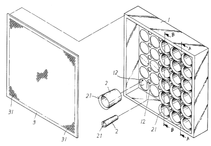
With reference to Figs. 4, 5, 6, 7A, 7B and 7C the sound
absorbing panel of the present invention is illustrated. The sound
absorbing panel 100 is formed by a frame l, a panel 3 and a
plurality of large and small sound absorbing barrels 2.
4
CA 02330199 2001-O1-04
The frame 1 (referring to Fig. l, 1A and 1B) is a rectangular
frame. The periphery of bottom plate of the frame is formed by
lateral plates connected as a rectangular frame. The outer edge of
each lateral plate is formed with a groove 11. A plurality of
concave seats 12 are installed at the interior of the bottom plate.
The panel 3 (see Fig. 3, 3A and 3B) is a rectangular plate for
matching to the frame 1. Many adjacent small tapered holes 31 are
formed thereon. The small tapered holes 31 have respective tilt
portions 32 at the surface of the panel 3.
The plurality of larger and smaller sound absorbing barrels 2
(see Fig. 2A, 2B, 2C and 2D) have round taper shapes (or any
camber shape without any tip portions, or straight barrel shapes).
The height thereof is suitable for the height of the lateral plates of
the frame 1. The diameter of the bottom thereof is suitable for the
concave seats 12 at the bottom plate of the frame 1, and the inner
edge at the top thereof has a tilt portion 21 . The bottom thereof is
formed with a smooth convex portion 22.
By aforesaid structure, a plurality of large and small sound
absorbing panels 2 are arranged in the frame and then is covered
by the panel 3 so as to be formed as an sound absorbing panel 100
so that the wave of noise is guided into the sound absorbing
barrels 2 in the frame 1 through the small tapered holes 31 on the
panel 3, and thus remained therein circularly without being
dispersed and therefore, the noise is reduced.
As shown in Fig. 8, a plurality of the sound absorbing panels
s
CA 02330199 2001-O1-04
can be assembled by a grid structure 4 from the grooves 11 at the
outer edges of the frame 1 so as to be formed as a larger sound
absorbing panel 100 for absorbing sound more effectively.
Furthermore, as the unit of a sound absorbing panel 100 has
a larger area, it can not be shaped by a single module. Therefore,
the present invention provides a simple way for assembly the
sound absorbing panel 100, which is convenient, and practical,
and thus the cost can be decreased. The frame 1 and panel 3 can be
machined individually. Moreover, the frame 1 is formed by lateral
plates, and the plurality of large and small sound absorbing
barrels 2 are formed by small molds so as to be mass-produced.
Then, the sound absorbing barrels can be arranged in the frame 1
spaced in an equal distance. Then, they are welded by high
frequency welding. Then the panel 3 is covered and is welded by
high frequency welding. Therefore, a sound absorbing panel 100
with a large area is achieved. Therefore, it can be manufactured
easily and conveniently without any extra devices.
With reference to Fig. 9 and 9A, another embodiment of the
present invention is illustrated. In the embodiment, a sound
absorbing barrel set 25, further referring to Figs. 10 and 1, is
formed by a plurality of sound absorbing barrel having different
diameters. Then a frame 1 with a predetermined size and the panel
3 are formed as an assembled frame. Thereby, the sound absorbing
barrel sets 25 can be placed in the bottom plate 15 in the frame 1
and thus, the assembly work is complete.
6
CA 02330199 2001-O1-04
Therefore, as shown in Fig. 12, by the steel frame in the
ceiling, the sound absorbing panels can be assembled therein. As
shown in Fig. 13, by installing a preset retaining frame, the sound
absorbing panels can be assembled one by one (such as sound
absorbing walls at two sides of a load) to achieve a desired effect.
Furthermore, the shape of the sound absorbing barrels may be
other shapes, such as smooth cambered shape, other than the round
shape shown in the specification.
Although the present invention has been described with
reference to the preferred embodiments, it will be understood that
the invention is not limited to the details described thereof.
Various substitutions and modifications have been suggested in
the foregoing description, and others will occur to those of
ordinary skill in the art. Therefore, all such substitutions and
modifications are intended to be embraced within the scope of the
invention as defined in the appended claims.