Note: Descriptions are shown in the official language in which they were submitted.
SHIELI?~D GRBLC AND METHOD OF MAKING SAME
Field of ~ho Invention
The invention re7.ates to a shielded cable and
moxo particularly, to a r_on-br,aidod dxop cable for the
transmission of. RF si~lnals .
s
BoCk rou d o~ha Ir~y ion
zn the tranr~missi.on of RF sigr_als such as
cable television signals, a drop cable is generally
used as the final, link in bringire the signals from a
:.riulk and distribution cable d~.reetly into a
subsr_riber's home. Co~'lventi.r_,nal drop cables include an.
insulated cEU:ter conductor that carries Zhe signal and
a conductive shioZd gurrousiding the center conc9urtQ= to
prevent signal. leakage and :interference from outside
J.S signals. Tn addition, the dx'op cable generally
includes a prot:eetive outer jaelcet to prevent moisture
fxom entering the cable. One cc~nunon construction for
drop Cable inclutjeB do in8ulated center con duetor, a
lalriindtpd tape formed of metal d.Ixd polymer layers
2a surrounding the center conductor, a layer of braided
metallic wires, and an outer protective jarkQt.
One p.rablem with eonventiona7 braided drop
ea~ale is that it is difficu.'.t to ar_t$ch to standard
connectors. In particular, the braided shield is
25 difficult to cut and attach to a standard connector and
normally must be folded back ovor the cable jacket
during connectoriZdtion of the cai~le, As a result, the
metal braid :increases installation time and costs.
Furthermore, forming the metal braid is genera.Ily a
30 time intensive process a_~d 3.imi.ts the rate at which the
cable can be ,produced. There~ore, there have been
attempt9 in the industry to eliminate the braid from
conv~ntior_al drop cable.
8U9$TITUTE HHEET
CA 02330299 2000-10-26
Put examp::e, tl.S patent Nos. 5,321,202;
, 414 , 213 ; arid 5 , 521, 3 3I to Hi. l lburn teach replacing
the outer braided shield of the eorivQrltional
conetruetion wish a metall~_c f_uil shlel.d Qr laminated
3 metallic tape shield and adding a plastic layer between
this shield and thG inner shielding tape. Although
this con:tructian elimiriate~ mar..al braids, is oreates
other connacCorization problems. Specifically, when
connectors are attached to theGe cablds. a speca.al
io coring or trirtaning roof is required to prepare the
cable for the connector to be attached tn the cable.
This rec~uix-es additional time duxing ttte
eonr~ectorization of these cables. fiu.rthermore, the
corm actor pull-off forc2 of the braidle3s cable, i.E.,
thp force neEded to pull thp connector off of the
cable, is undesirably reduced as compared to braided
cables.
C3erman applications D~ 3931'741A and DE
3141fi36A descxibe alternal.ive cable cortstni.ctions. Iri
1o particular, ,pD 3331?dIA describes a table that includes
an inner conductive core, insulation aurroundina the
inner Cond.uCtiVe Core. and an outer conduCtGr
surroa~nding the insulation. The outer conductor
compri6es two unilaterally metaili.zed films with
~'S condwetive wires exxanged ti~ereY~eLtween. nE 3241636A
describes a cable that includes a copper conductor, a
plastic covering Surrounding the copper conductor, a
copper mesh euz~roundiag the plastic as an inner shield,
side-hy-aide arranged wires t-_hat surround the inner
30 shield, a metal foil that 8urround.s the wires, and a
second copper mesh surrounding the metal foil as an
outer shield.
S~mrnary of fihe ~v~ntion
35 The present inVent~on provides a non.-bra:~ded
drop cable that can be easily attached to a cor_nector
8t188TZTUTB 8HE8T
CA 02330299 2000-10-26
08-05-2000
- 3 ~-
and l:hat eon properly anchor s connector to prevent
connector pull-off once the cable is connectori~ed.
Furthermore, the present-. i:nVcntiGn provide, a Chop
cable with sufficient shielding to prevent, signal
leakage arid interference .from extraneou , Signals .
Tre9e features are provided. by a non--braided
shielded cable that includes a cable care comprising a
centex conductor and a die~eetric layer surrounding the
center conductor, a fi.r.st electrically conductive
l0 shield surrounding the cable core and bonded thereto, a
second electrically conductive shield surrounding the
first Shield, and a cable jacket surrou.ndi.ng the seco:~d
Shield rnd bonded thEreta. According to the invention,
an in~aretitial layer i.g located bQtwcen the first and
1S second srield~ and ie composed of elengate strands
disposed between said First and second shields so as to
be freely displaceable axia113r while also serving to
space the first and second shields apart f-rom one
another.
3o Tn a preferred embodiment of the invention,
the first and second shields ucpd in the cables are
bonded metal-polymer-metal laminate tapes extend~.ng
longitudinally of the cable and hz~virg overlapping
long.iLudln3l edges to produce 100$ shielding coverage
25 of the center conductor. Preferably, the first
shielding tape is an aluminum-polyolefin-aluminum
laminate tape and the second shielding tape ig an
aluminurn,polyeeter-aluminum laminate tape. The strands
of the inter3titidl layer axe typically helically wound
around the first shielding tape and are formed of metal
wires and/or textile yarns. Preferably, these strands
are metal wires covering less than 30 percent of the
surface o; the underlying first shielding tape. The
motel wires can be provided as more than one laye~
35 having different orientations such as two layers have
opposite helical orientations (e. g., countercioekwise
8U88TITI1TE SHEET
08-05-2000
--4-
and clockwise). ~rha yarns tax Lhe interstitial layer
typically saver leES than 50 percent of the surface of
the first shielding tape and are se7.eeted from !she
group coneistirg of polyester, cotton and aram~id yams
s arid bJ.ends l.hereof. The interstitial layex can includs
both yarns and metal wires disposed alongside the
yarns, and can also 3.nclude a water blocking material.
The present invention also provides a method
of making a shielded cables. In the manufacture of
f0 these cables, a cable core comprising a center
conductor and a dielectric layer surrounding th.e center
conductor~~is advanced and a first electrically
conductive shielding tape is longitudinally wrapped or
"cigarette-wrapped~ around the cable core. The
~s interstitial layer is app7.ied to the first shielding
cable typ_i.cally by helically wrapping the strands
around the first shielding tape. A second shielding
tape is then longitudinally wrapped over the
interstitial Iayer and a cables jacket extruded over the
second shielding tape to produce the cable.
Preferably, the method further evmprises bonding the
first shielding tape to the cable core and bonding the
second shielding tape to the jacket. The shielding
tapes are preferably bonded metal-polymer-metal
25 laminate tapes having longitudinal edges that are
positioned in an overlapping relationship. These
laminate tapes also preferably include an adhesive on
one surface thereof, witr. the first shielding tape
including an adhesive on the inwardly facing surface
adjacent the e3Y~le core-and the second shielding tape
including an adhesive on the outwardly facing surface
over which the outer jaekAt is extruded to provide the
desired bonds in the shielded cable.
The shielded cables of the invention are easy
~5 to attach to standard connectors. Specifically,
because the shielded cable is not braided, the problems
SV88TITTJTE SHEET
CA 02330299 2003-07-03
...
associated with braids azwe n<,~t: experir~nced during
connectorization of the shie:l.ded cab:l~=~ of: the ir~ve:ntic:m,
In addition, th~~ int.ersti_t:i.al. layer :in the cable of the
invention is composed of st.rancls ttia~~ are axially
displaceable and thus do r~.ot requ:i r-e ~::ri.mming pr i.or tc:~
connectorization, ~'urthEaz,mo:re tr~e~~e ;zxi.ally displaceable
strands assist in anchoring .r..he ~co~zne~.;t.oz- to the cable,
thus increasing the pull--off resisr:ar~~w of the cable,
Accords ng to or~c> aspect ~f t.he1 present
invent: ion, there is provided a shi~:~lclead cable ccrnp:risi.ng:
a cab.LE~ care cc~mpr.i.:~irrg a~ cf::aruter conductor and
a dielectric layer surrounc~:irrg the cknrt:er con.ducto:r;
a first: electri..ca:li.y cc~n~..lu~::t.i..ve shield
comprising a '.bonded metal-po:Ly~mer---net.<:o.l. laminate tape
extending lon~~ir_,zdin.ally of t:.he c:able,, surrounding said
cable core and bonded thEret~.s, tl~;~ bcm~ded metal-polymer--
metal laminate t:~pe having ov~erlappimc~ Longi.tudina:l edges
surrounding said cable care and b~,~ndc~c~ thereto;
a second elect.r i.ca:l l y c°,:~Yiduc::t..i~,re shielr~
surrounding said first shield corrzpr~is:ar~g a bonded metal-
polymer-metal laminate tape e~xt~end~.ng longitudinally of
the cable and having over:l.ap~~~i.ng L~:~rac~e..tud.inal edges;
a c;~b_LF~ jacket aurr~c~ur~dir~,g ~:yaid second shield
and banded therE=_t a; and
an int~~~rst it iai. Lawyer 1.~~~::.at~cd between said
first and second shields, :~aa.d int.~~=r~t:i.tial layer being
composed of elongate strands disposed between said first
and second sh.ie:Lds so as to t:~e= fx:~ely displaceable
axp_ally while a:Lso servir~.r~ tc~~ spa~:~.~ said first arZd second
shields apart f rom ene ar~ot:hr~,r .
According to ar~othc=_:r asps~ct: of the present
invention, there is provided a method of making a.
shielded cable comprisi~y t.t~E~~ ste,~:::~ ~~>i'r
CA 02330299 2003-07-03
~, a _.
advancing a cable ~e:c~e compui.sing a center
conductor and a die:l a ctr:ic.~ l;~~ye~v s~.~r:r~~unding the' center
conductor;
Longitudinally wra~>p:irrg a f:.rst: bonded metal-
poiyrner-metal iae~lir a;~e sr .~I,..ii.~ng ;=:~pfv around the cable
core and overlapping Ionc~itucii_nal edgr~ s of the e;hielding
tape;
bonding the. first ~hield:i.n<~ tape t:o tr,e cable
core;
applying a~n int::.ers't:itial layer composed of
axially displaceable elongate 5tx;~zd::~ around t:he first
shielding tape;
longitudinally w:rappirrc~ a second bonded metal-
polymer-metal larnin~.te sr:aield.ing t,~~pe around the
interstitia:L layer a.nd overlapping longitudinal edges of
the shielding tape;
extruding a cak>le j a<~iCet art~urrd the second
shielding tape; and
bonding the cak>Ie j ackF:t to the second.
shielding tape.
Brief Dt~scriv::tior:~ of the Drawings
Other features ar-fd advamttac~~~:; of the present
invent;ic>n will becon~E~ apparerut from tam following
detailed descript~ior. of t_Lne :i.ruver~t~:i.~~rz taken in at:.~cordance
with the drawirags, in which;
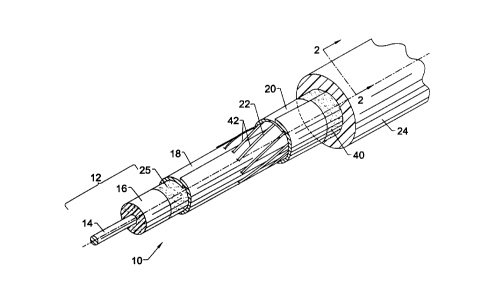
Figure 1 is a ~.7erspect.irre ~r.~ew of a sh.ieldec~
cable accordi:rrg to the ir~vent.iorz lnavimg pardons thereof
partially removed for purposes of i.:Ll~.rstratio:n;
Figure 2 is a part i.al cr-:ass--sectional view of
the shielded cable of Figure l t.aknan ar7_clng :Line :z-2;
Figar_E= 3 is a ::c°harroat~..c~ i.l::L,.~stration cf' a
method of making a =~hielcz.ed cable <~cc~:arding to t:he
CA 02330299 2003-07-03
cy~ ~}
invention;
Figure 4 a..s a ~>erspect i Ve v Lew of a sl-~ielded
cable according to the ir~vent:~_on attached t.o a ~;tandard
one-piece connector and wat:h parti:~n5 k>x~oken away for
purposes of illustration; anu
Figure 5 i.s a longitudinal <:ross-sectional ~.riew
of the connectorized cab_i.e: ofFigure <:E taken along line
5-5.
Detailed Description of the ~axeferred Embodiments
Referring now t:c~ Fi.c~ure~~s 1 :.~rx~~~ 2, th.eze is
shown a shielded cable 1(i.n a~~c>e-:~a~u.:e with the present
invention. The shiesLded cable 1.C) is ~~enerally
,,,
1:.
QS-05-2000
r
known as a drop caLle and is used in the transmission
of RF signals such as eabie television signals.
Typically, Lhe over-Che-jacket diameter of the cable 10
is between about 0.2~ inches (0.61 cm) and 0.11 inches
s ( 1, O4 crif
The cable ~.0 includes a cable core l~
comprising an elongate center conductor 14 and a
dielectric layer 1.6 surrounding the center conductor.
A first shield preferably farmed of. a first shielding
tape 18 surrounds the cable core 1~ and ie bonded
thereto. A second shield preferably formed of a second
shielding tape s0 surrounds the first shielding tape.
The Lirst and second shielding tapes 18 and 20 prevent
leakage of the signals being transmitted by the center
:5 conductor 1.4 and interference from outside signals. An
interstitial layer 22 is located between the shielding
Lapes 18 and 20 and spaces the shielding tapes apart
frorl one another. A cable jacJcQt 24 surrounds the
second shielda.ng tape ZO to protect the cable from
34 moa.sture arid othex environmental effects and is bonded
to the second shielding tape.
Ae mentioned above, the center conductor 14
in the shielded cable 10 of tho invention is generally
used in the transmission of RF signals such as cablo
25 television signals, The center conductor 14 is
preferably formed of copper Clad steel wire but other
conductive wire (e.g. copper) can also be used, the
dielectric layer 16 carr be formed of either a foamed or
a solid dielectric material. Preferably, the
o dielectric layer 16 is a material that reduces
attenuation and maximizes signal propagation such as a
foamed polyethylene. In addition, solid polyethylene
may be used.
The cab7.e 10 :Further includes a first or
35 :.prier shielding taps 18 surrounding the cable core 13
SUS&TITOTE 8138ET
CA 02330299 2000-10-26
PCT; US99i08465
08-05-2000
and bonded to the cable core by an adhesive layer 25.
The longitudir_al edges of the first shielding tape 18
a.re typically overlappea so that 100$ shielding
coverage is provided by the first shielding tape. The
first shielding tape 18 includes at least one
conductive layer such as a thin metallic foil layer,
Preferably, the first shielding tape 1A is a bonded
laminate tape including a polymer layer 26 with metal
layers a8 and 30 bonded to opposite sides of the
polymer layer. The polymer layer Z6 is typically a
polyolefiri (e. g. polypropylenes or a polyester f_ilcr~.
ThQ metal layers 29 and 30 are typically thin aluminum
foil layers. To prevant cracking of the aluminum in
bending, the aluminum foi_1 layers can be formed of an
aluminum alloy having generally the same tensile and
elongation properties as the polymer layer. Tapes
having this construction are available under the HYDRAe
trademark from Nept.co, zn addition, the first
shield=ng tape 18 preferably also includes an adlze$ive
2p on one surface thereof to provide the adhosive layer 25
between the first shielding tape and the cable care 12.
The adhesive is typically formed of an ethylene-ac=~ylic
acid (EAA), ethylene-vinyl acetate (EVA>, or ethylene
methylacrylate (EMA) copolymer or other suitable
35 adhesive. Preferably, the first shielding tape 18 is
formed of a bonded aluminum-polypropylene-aluminum
laminate tape with an EAA copolymer adhesive.
A second or outer shielding tape zQ surrounds
the first shielding tape 19 and also provides shielding
30 of the center conductor id. The longitudinal edges of
the second shielding taQe 20 are typically overlapped
and the second shielding tape is preferably bonded to
the cable jacket aa. The second shielding tape 30
includes at least one conductive layer such as a thin
35 metallic foil layer and is preferably a bonded laminate
8U8BTITUTE BHEBT
CA 02330299 2000-10-26
08-05-2000 PCT!US99%084
-8-
l:ape including a polymer J.ayer 3d with metal layers 36
and 38 bonded to opposite aides of the polymer layEr-as
described above. However, to provide adde3 strength
and connector retention to the shielded cable 10, the
second shielding tape ZO is preferably a bonded
alumir_urn-polyester-aluminum laminated tape, In
addition, to prevent cracking of the aluminum in
bending, the second shielding tape 20 can include
aluminum alloy foil layers having generally the same
14 tei~SiJ.e and elongation properties as the polyester such
as described above with respect to the first shielding
tape 18. The second shielding tape 20 tyQieally also
inca.udes an adhQSive on one surface thereof that forms
an adhesive layer 4Q to provide a bond between the
~5 second shielding tape and the cable jaclcet 24.
Preferably, the adhesive is an EAR copolymer for
polyethylene jackets and an >aVA copolymer for polyvinyl
chloxide jackets.
In between the first shielding tape 1A and
2o the second shielding tape 20 is provided an
interstitial lay~r ~2 that spaces the shielding tapes
apart from one another. The intezscitial layer 22 is
composed of elongate strands da disposed be=wean the
first shielding tape Z8 and the second shielding tape
20. T;:e elongate strands 42 are positioned and
arranged between the tapes 18 and 20 in such a way that
they are freely displaceable axially, As described in
more detail below, this allows the strands is to be
displaced when the cable 10 is attached to a standard
3o connector. zn the illustrated embodiment, this is
achieved by the strands being loosely arranged between
the tapes 18 and 20 without any bonding to one another
or to the tapes. Alts=natively, a binding agent or
adhesive could be utilized to si:abiliae the strands
35 during manufacture, so long as the bond is relatively
&QSSTITZJTE ~JEET
CA 02330299 2000-10-26
w a .r. ne-vrr~ rm ,rrr
08-05-2000 PCT- U S99-'08465
_g_
weak and permits axial displacement of the atrands
during connectorization.
The scrams ~2 foriring the interstitial layer
as are preferably hel.ica7.ly arranged about the first
shie7.ding tape 20. PreFerably, the stx'arids 42 are
metal wires or textile yarns. Metal wires are
especially preferred because they impart morn strength,
provide a conductive bridge between the shielding
layers, and increase the atren,gth of the attachment
t0 between the cable arid connector. Exemplary wires
include copper or aluminum wires having a generally
circular cross-section and a diameter of up to about
0.01 inch (0.025 cm). The metal wires can be applied
a.n one layer having a predetermined helical orientation
!5 or in more than one layer (e. g. two layers) with each
layer having alternating opposite helica:L orientations.
For example, a first laS~er of wires can be applied in a.
clockwise orientation and a second layer of wires
applied in a counterclockwise orientation. In any
?o event, the metal wi.z~ss are applied such that they are
freely d~.splaceab~.e axially and thus are not interlaced
in the manner used to make braided wires. To that end,
the metal wires preferably cover less than 30 percent
of the surface of the underlying shielding tape 18, arid
25 more preferably between about 10 and 20 percent of one
surFace of the underlying shielding tape.
As mentioned above, the str$nds 42 can also
be composed of textile yarns. Exemplary yarns inc7.ude
polyester, aramid and cotton yarns, and blends thereof.
3o Preferably, the yarns are continaoua multifilarnent
polyester yaxns. The yarns can also be semiconductive
cc contain conductive filaments or fibers to provide a
con3uctive bridge between the shielding tapes 1.8 and
20. The yarns can suitably provide less than 50
35 percent coverage of the underly,.:ng shielding tape 18
and, for example, r.~ay cover between 20 and ~D percent
BUH~TITI?TL SF~ET
CA 02330299 2000-10-26
03-05-2000 PCTi U S99!08~
-1G-
of the surface of the First shielding tape. The yarns
are preferably helically arranged about the f.irat
shielding tape 16 and can be used alone to form the
interstitial layer ~Z or can be combined with metal
s wires, Fox example, the yarns and metal wires can be
disposed alongside one another to form the interstitial
layer a7 or in separate layers as described above.
The interstitial layer ZZ can also incJ.ude a
water blocking material to trap dry moisture that may
1o enter the cable 10 and prevent corrosion of the metal
layers in the cable. The water blocking material can,
for example, include a water swellable powder such as a
polyacrylate salt (e. g. sodium polyacrylate). This
water blocking powder can be provided in the yams used
~S as strands 42 in the interstitial layer 22, applied to
the strands in the interstitial layer, or provided on
the surface of the first or second shielding tape 1B or
20 adjacent the interstitial layer.
As shown in rr~igures 1 and 2, the cable 10
?o generally also includes a protective jacket Z4
surrounding the second shielding tape 20. The jacket
24 is preferably formed of a non-conductive material
such as polyethylene or polyvinyl chloride.
Alternatively, a low smoke insulation such as a
25 fluorinated polymer can be used if the cable 10 is to
be installed in air plenums requiring compliance with
the requirements of UL91~.
Figure 3 illustrates a preferred method of
:raking the shielded cable 1.0 of the invention. As
3o shown in Figure 3, the cable core 12 comprising a
center conductor 14 and surrounding dielectric layer. 16
is advanced from a reel 50. As ~he cable core 12 is
advanced, a first shielding tape 18 is supplied from a
reel 52 and longitudinally wrapped ox "cigarette-
wrapped" around she cable core. As mentioned above,
$U88TITUTR SHEET
CA 02330299 2000-10-26
08-05-2000 PCTiUS99~0846;
-~1-
the First shielding tape 18 is preferably a bonded
metal-polymer-metal laminate tape having an ad?~esive'on
one surface thereof. The first shielding tape 1B is
applied with the adhesive surface positioned adjacent
s tine underlying cable core la. IC an adhesive layer is
not already included on the first shielding tape 18, an
adhESive layer can be applied by suitable means such as
extrusion prior to longitudinally wrapping the firs
shielding tape around the core 12. One or more guiding
rolls 54 direct the drat shielding tape 1B around the
cable core with longitudinal edges of the first
shielding tape overlapping to provide 100 shielding
coverage of the cable core 12.
The wrapped cable core is next advanced to a
t5 creel 56 that helically winds or 'serves" the strands
4~ around the first shielding tape 18 to form the
interstitial layer ZZ. The creel S6 preferably
includes only as many spools 5B as are necessary to
provide the desired coverage of the first shielding
tape 1B described above. The creel BB rotates in
either a clockwise or counterclockwise direction to
provide helical winding of the strands ~2. Additional
creels (not shown) can also be included to produce more
than one layer of strands dZ in the interstitial layer
35 ZZ. In addition, if a water blocking material is not
provided in the strands 4Z or on the surface of the
first or second shie7.d~_ng tapes 18 or 30, a water
swellable powder can be applied to the interstitial
layer. 22 by suitable means (not shown) to prevent the
3o migration of moisture in the cable 10.
Once the interstitial layer 22 has been
applied, a second shielding tape ZO is provided from a
reel 60 and longitudinally wrapped around the
interstitial layer. As mentioned above, the second
35 shielding tape 20 is preferably a bonded metal-polymer-
SU88TITUTB BJ3E8T
CA 02330299 2000-10-26
n n ~rW nCn c~LJCCT
08-05-2000 PCT; US99'08465
-i2-
metal la~rinate tap~ having an adl:ssive layer on one
surface thereon. The second shielding tape 20 is
applied with the adhesive layar facing outwardly away
from the interstitial layer Z2, i.e, adjacent the cable
jacket a4. One or more guiding rolls 6a direct the
second s~~.i_elding tape 20 around t;~e interstitial layer
2Z with longitudinal edges of the second shielding tape
overlapping to provide 1fl0~ shielding coverage.
The cable is then advanced to an extxuder
14 apparatus 64 and a polymer melt is extruded at an
elevated temperature around the second shielding tape
ZO to form the cable jacket 2d. If the second
shielding tape 20 does not already include an adhesive,
an adhesive layer 40 can be applied to the second
shielding tape by suitable means such as coating or
extrusion, or it can be coextruded with the cable
jacket 24. The heat from the extruded malt generally
activates the adhesive layers 25 and 40 to provide a
bond between the cable core 12 and first shielding taps
1A, and betinreen the second shielding tape 20 and the
jacket Zd. Once the protective jacket Z4 has been
applied, the cable is quenched in a cooling trough ~6
to harden the jacket and the cable is taken up on a
reel 68.
figures 4 and 5 illustrate the shielded cable
10 of the invention attached to a standard connector
70. The cormector 70 shown in Figures g and 5 is a
threaded one-piec~ connector of the type conventionally
used in the cable television industry. However, other
types of connectors such as two-piece compression
connectors could also be used in accordance with the
invention.
The standard one-piece connector 70 typically
incudes an inner sleeve or bushing 72 and ar_ outer
:~5 slee~~e 74. As slzown in Figure 5, to attach the
HQHBTITOTF SF3EET
CA 02330299 2000-10-26
.. l 1 , 1.",: V'J 1.'111.11 1 ~ l"l :LuJ . 1~. L' ! .\U
1 .. _ n
08-05-2000 PCT;'US99~ 0846
-13-
shielded cable 10 of the invention to the connector 70,
the shielded cable is typically prepared by cutting
away a portion of the die~.ectric 16 and first shielding
tape 18 to expose a short length (e. g. 1/4 of an inch
s (0.69, cm)) of the center conductor 14 protruding from
the dielectric. The second shielding tape 20 and
jacket 24 are stripped away an additional short length
(e. g. 1/4 of an inch (x.69 cm)) exposing the dielectric
16 a.nd first shielding tape 1B. The connector 7~0 is
!o then attached to the cable 10 by inserting the bushing
72 between the shielding tapes 18 and 20 and inserting
the outer sleeve 74 around the jacket 24. The outer_
sleeve 74 is then crimped down onto the cable 10 using
a suitable crimping tool to complete connectorization
is of the cable. Hecausa the strands 42 forming the
interstitial layer Za are freely moveable between the
two shielding tapes 18 and 20, the strands axe pushed
back axially as the connector bushing 7Z is inserted.
Insertion of the connector does not require special
2o preparation ox use of a coring tool, As best shown, in
Figure 5, a portion of the axially displaced strands 42
become lodged or tucked between the connector bushing
7~ and 'the second shielding tape 20. These strands 42
serve to help anchoz~ the connector bushing 72 in the
35 cable 10 and thus increase the pull-off resistance of
the cable, i.e., the force necessary to pull the
connector 70 off of the cable.
':he benefits of the invention can be
demonstrated by determining the pull-off force between
3o cables and standard connectors using the test method
described in Society of Cable Telecommunications
Engineers (SCT.E) Documer~t IPS-TP-401, issued January
17, 1991 and entitled "Test Method for Axial Pull
Connector/Cable.° Using this method, RG5 cables raving
35 an over the jacket diameter of 0.272 inch (0.691 cm)
8UH8TITUTB $H$ET
CA 02330299 2000-10-26
08-05-2000 PCT/US99'08465
_1g_
were compared. Cable A was constructed using metal
wires according to tile invention and Cable B was
constructed using a foamed polyvinyl chloride layer
between wielding tapes. The results are provided in
Table 1 and demonstrate the increased pull-off
resistance of the cables according to the invention.
TAHT.~S 1
Connector/Cable Connector
Pull-Off
Force
One Piece Cr~.mpConnector;
Cable A 64 lbt (280N)
Cable H 30 l.b~(130Lv1)
Two I?iece Compression
Corulector;
Cable A 61 lb~ (270N)
Cable B 3~ lbf (160N)
Jo
In audition to providing ease of
connectorizat~.cr. and enhanced connector pull-oft
resistance, the shielded cable 10 of the invention can
be produced at a better rate than conventional braided
Js cables and at lower cost. Furthermore, the shielded
cable sufficiently shields the RF si.gnals carried by
the center conducCor~ accordingly, the shielded cable
of the invention overcomes many of the problems
associated with prior art cables.
SBHSTTTUTF SHEET
CA 02330299 2000-10-26