Note: Descriptions are shown in the official language in which they were submitted.
CA 02330474 2000-10-27
24-03-2000 PCT/DE99/01262
GR 98 P 1635 P
PCT/DE 99/01262
- Description
Bidirectional module for multichannel use
The invention relates to a transmission and reception
module for bidirectional optical message and signal
transmission according to the precharacterizing clause
of Patent Claim 1.
For many years, it has been prior art in fiber-optic
message transmission to transmit at least one channel
in each case, bidirectionally, using the full-duplex or
half-duplex method. By way of example, EP-A-0 463 214
discloses a transmission and reception module, which is
known as a BIDI module, for bidirectional optical
message and signal transmission. In this module, the
two active components {the light transmitter and the
light receiver) are installed as autonomous components,
encapsulated such that they are hermetically sealed, in
a common module housing, in whose hollow interior a
beam splitter and lens coupling optics are arranged,
and which has a fiber connection for a common optical
fiber. The transmitter injects an optical signal into
the attached glass fiber, while another optical signal
can be received from the same fiber, at the same time,
or else at a different time. The two signals are
separated by the beam splitter, which may also contain
a WDM (wavelength division multiplexing) filter, in
which one specific wavelength can be reflected, and
another can be passed.
If, apart from the respective one channel in each
direction, it is intended to transmit a further channel
in at least one direction, then an external fiber
AMENDED SHEET
CA 02330474 2000-10-27
24-03-2000 - la - PCT/DE99/01262
GR 98 P 1635 P
PCT/DE 99/01262
splitter or an external WDM filter can be installed in
the supplying glass fiber, for example upstream of the
module. However, this represents a relatively
impracticable solution. On the other hand, a so-called
multichannel transceiver module is proposed in German
Patent Application No. 93 114 859.7,
AMENDED SHEET
CA 02330474 2000-10-27
24-03-2000 - 2 - PCT/DE99/01262
GR 98 P 1635 P
PCT/DE 99/01262
in which at least one further light transmitter and/or
light receiver with associated lens coupling optics and
at least one further beam splatter are provided in the
common housing of a conventional BIDI module as
described above. The further light transmitter or
transmitters and/or light receiver or receivers is or
are in this case designed in particular in the form of
the so-called TO (transistor outline) standard
construction, as has also been described, for example,
in German Patent Application No. 93 120 733.6. However,
this solution has the disadvantage that bidirectional
transmission of a further channel makes it necessary to
install two TO modules, namely a transmission module
and a reception module, in the common housing.
EP 0 644 668 A1 discloses a transmission and reception
module for bidirectional optical multichannel
transmission having a light transmitter, a light
receiver, a fiber connection for a common optical
fiber, lens coupling optics and a beam splatter, which
is positioned at an intermediate point in the beam
path, and is arranged in a common housing. At least one
further light transmitter and/or light receiver, with
associated lens coupling optics, and at least one
further beam splatter are provided in the common
housing. In the illustrated exemplary embodiments, the
beam splatters are arranged one behind the other in the
beam path, and parallel to one another, inclined at an
angle of 45° to the beam path, between the fiber
connection and the opposite light transmitter, in the
axial direction of the optical fibers in the housing.
EP 0 487 391 A1 relates to an optical bidirectional
transmission and reception module having a common fiber
connection opening, a plurality of transmitters, a
plurality of receivers and a corresponding plurality of
AMENDED SHEET
CA 02330474 2000-10-27
24-03-2000 - 2a - PCT/DE99/01262
GR 98 P 1635 P
PCT/DE 99/01262
light paths. Beam splatters are in each case arranged
upstream of the transmitters and receivers in two
mutually parallel levels, the object of which beam
splatters is to allow light at a wavelength
corresponding to the respective transmitter or receiver
to pass, and to reflect light at all other wavelengths.
A compact bidirectional transmission and reception
device is disclosed in U.S. 5,416,624, which has a
planar convex lens with a beam-splitting wavelength
filter arranged on its planar surface. This lens is
positioned between a transmitter and a receiver, so
that this arrangement produces a compact transmission
and reception device. In addition, in Figure 4, this
document describes a linear array of such lenses, by
means of which radiation beams from such a linear
arrangement of transmitters can be injected into such a
linear arrangement of optical fibers.
Accordingly, the present invention is based on the
object of specifying a transmission and reception
module having a multichannel capability for
bidirectional optical message and signal transmission,
which is designed such that it is space-saving and
which can be expanded by adding further bidirectional
channels in as simple a manner as possible.
This object is achieved by the characterizing features
of Patent Claim 1.
The invention described further below with reference to
exemplary embodiments achieves this object in such a
way that it describes a compact module in which at
least one transmitter and at least one receiver are
combined in a transmission/reception unit which is
installed in the common housing, and
AMENDED SHEET
CA 02330474 2000-10-27
98 P 1635 - 3 -
at least one further such transmission/reception unit
or at least one transmission unit or one reception unit
- are provided in the common housing.
In one preferred embodiment of the present invention,
the transmission/reception unit is designed in
accordance with a bidirectional transceiver module
which is described in German Patent Application
No. 93 120 733.5 and is also referred to as a TO-BIDI
module. Furthermore, the at least one transmission unit
or the at least one reception unit is preferably
designed as TO modules [sic]. The invention thus
describes a compact module which combines the
assemblies of the known BIDI module and those of the
TO-BIDI module, with their characteristics.
The multichannel BIDI produced in this way is thus also
able to transmit one channel, or more than one channel,
in the respective directions simultaneously, in
addition to the normal bidirectional function on two
bidirectional channels.
A conventional BIDI module having 2 bidirectional
channels, that is to say one transmission channel and
one reception channel, thus becomes a module with
3 channels by the use of a TO transmission or reception
module by means of a TO-BIDI having the same external
dimensions. If one TO transmission module is replaced
by a TO-BIDI, this results in one transmission and
reception channel, and a second reception channel. If
one TO reception module is replaced by a TO-BIDI, this
correspondingly results in 2 transmission channels and
one reception channel. Finally, if a TO laser and TO
receiver are each replaced by TO-BIDIs, then this
results in 2 transmission and 2 reception channels,
that is to say 4 channels. This can, of course, also be
expanded to the module arrangement having 3 TO
components, resulting in modules with 5 and 6
CA 02330474 2000-10-27
98 P 1635 - 3a -
channels. The corresponding expansion to even more
channels can be achieved by appropriate lengthening of
- the module
CA 02330474 2000-10-27
98 P 1635 - 4 -
by simultaneous outputting by means of additional
filters in the optical beam path to the corresponding
additional TO components. In optical terms, this can be
done in a particularly simple manner if the optics of
the TO components are designed for one collimated beam
in the module. The maximum possible number of channels
is thus twice as great as the number of connected
TO-BIDIs, or is correspondingly less if a single TO
transmission or reception component is used instead of
a TO-BIDI.
A further major advantage of the arrangement according
to the invention is that the optical channel
separations in the TO-BIDI and BIDI module may be of a
different type, or else of the same type. If, for
example, a WDM filter is used for virtually no-loss
separation of 2 wavelengths in the module, then not
only can the separation in the TO-BIDI be carried out
in the same way once again, using a WDM filter to 2
further wavelengths, but a 3dB-beam splitter can also
be used to split the. intensity of one wavelength
between in each case one reception channel and one
transmission channel.
This means that the use of TO-BIDIs as TO components in
the multichannel BTDI makes it possible to operate each
individual channel bidirectionally, particularly in the
case of WDM systems having a number of discrete
wavelengths (for example in accordance with the ITU
Standard, 4 wavelengths or even more), so-called HD-WDM
systems. In comparison with multichannel HD-WDM systems
as normally used until now, and which are operated only
unidirectionally, this results in full bidirectional
functionality on each WDM channel. This means that, for
relatively recent multichannel WDM transmission on
individual glass fibers, the arrangement according to
CA 02330474 2000-10-27
98 P 1635 - 4a-
the invention allows the transmission capacity of the
fibers to be doubled by means of bidirectional
operation.
CA 02330474 2000-10-27
98 P 1635 - 5 -
Thus, using the arrangement according to the invention,
two bidirectional module types with different optics
are skillfully combined such that a new module type is
produced whose functional characteristics are
considerably better than the intrinsic functions of the
individual module types. Thus, using the arrangement
according to the invention, it is not just possible to
produce any desired multichannel modules, but also to
operate one-directional multichannel HD-WDM
transmission systems fully bidirectionally. The
wavelength stabilization which is required, for example
by means of temperature stabilization, can in this case
be carried out by appropriate temperature stabilization
of the entire module, as described, for example, in
German Patent Application No. 93 114 860.5.
The invention will be explained in more detail in the
following text with reference to exemplary embodiments
and in conjunction with Figures 1 to 4, in which:
Figure 1 shows a basic embodiment of the present
invention;
Figures 2a, 2b show further embodiments of the present
invention with 3 TO components;
Figures 3a, 3b, 3c show further embodiments of the
present invention with 5 TO components;
Figure 4 shows a further varied embodiment of the
present invention with n TO-BIDIs;
Figure 5 shows a transmission/reception unit in the
form of a TO-BIDI.
CA 02330474 2000-10-27
98 P 1635 - 6 -
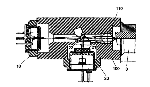
Figure 1 shows a basic embodiment of the present
invention. The basic version of a multichannel BIDI is
formed from the common housing body 100, 2
subcomponents 10 and 20 and the common SM (single mode)
connecting fiber_ 0. The lens coupling optic 110 for the
common optical fiber 0 is arranged in the vicinity of
the end of the optical fiber 0 in the form of a
spherical lens, although this may also be omitted if
the overall coupling optics are appropriately designed.
The subcomponent 10, which is fitted on the module
axis, is a transmission/reception unit which contains a
transmitter and a receiver. This transmission/reception
unit may, for example, be a TO-BIDI module as mentioned
above, that is to say it may be a bidirectional
transmission/reception unit produced using the standard
TO construction mentioned above and as described in
German Patent Application No. 93120733.6, which has a
full bidirectional function for a reception channel A,
for example for 1480 nm, and a transmission channel,
for example for 1300 nm. The subcomponent 20 which is
installed in the common housing 100 is a TO-PIN diode
in the illustrated exemplary embodiment, that is to say
a diode receiver, which is likewise produced using the
standard TO construction mentioned above, for a further
reception channel B which, for example, is set to a
wavelength of 1550 nm. The fully selective-wavelength
channel separation with an efficiency of >95o in each
case is carried out for the further reception channel B
using an appropriate WDM filter, which is contained in
the beam splitter 22, on the beam axis, using
conventional BIDI technology. A stop filter 21 can also
be placed upstream of the TO housing of the
subcomponent 20, in order to mask out undesirable
wavelengths.
The corresponding channel separation for the
transmission channel and the reception channel A within
the subcomponent 10 can be
CA 02330474 2000-10-27
98 P 1635 - 7 -
provided using the known TO-BIDI technology described,
for example, in German Patent Application
No. 93120733.6, mentioned above.
The essential elements of this construction will be
described once again here, with reference to Figure 5
in order to assist understanding. Figure 5 shows a
bidirectional transmission and reception module using
TO construction (TO-BIDI module), which can be used as
the subcomponent 10. The transmission and reception
module essentially comprises a laser chip 1, which has
lens coupling optics 6, as a light transmitter, a light
receiver 8 and a beam splitter 9 which is arranged at
an intermediate point in the beam path and is at least
partially surrounded by a housing 7 on to which a light
inlet and outlet window 11 is glazed. The laser chip 1
is arranged on a common substrate 2, which is
preferably composed of silicon and, as a submount, can
be mounted, for example, on a baseplate 19 of a TO
housing. The laser chip 1 is arranged on the common
substrate between two substrate parts 3, 4, whose side
surfaces which are adjacent to the optical resonator
surfaces of the laser chip 1 are provided with mirror
layers 5 and are inclined at an angle of approximately
45° to the resonator ~urf,aces, so that the coherent
radiation emitted from the laser chip 1 is deflected
upwards, virtually at right angles to the surface of
the common substrate 2, as a divergent light beam onto
the lens coupling optics 6, which are arranged above
the laser chip 1. The two substrate parts 3, 4 are
preferably composed of glass or, like the substrate 2,
of silicon, and have a trapezoidal profile. The lens
coupling optics 6 are arranged and mounted on at least
one substrate part, in this exemplary embodiment on the
substrate part 3, such that the radiation emitted from
the laser chip 1 strikes it virtually at right angles.
CA 02330474 2000-10-27
98 P 1635 - 8 -
The mirror layer 5 which is adjacent to the front face
of the laser chip 1 is provided with a beam splitter 9
which reflects the radiation emitted from the laser
chip 1 and passes the radiation injected from the
exterior via the lens coupling optics 6. The light
receiver 8 or an optical coupling for the light
receiver 8 is provided underneath the beam splitter 9,
on the bottom face of the common substrate 2.
The beam splitter 9 forms an optical separating device
for different light wavelengths or for the same light
wavelengths. A separation of greater than 95 percent
can be achieved for different light wavelengths in the
transmission path and reception path, that is to say
when the beam splitter is operated on a selective-
wavelength basis. 50 percent separation, for example,
or some other separation, can be set if the wavelength
in the two paths is the same. In order to achieve
bidirectional transmission, only the mirror layer 5
which is adjacent to the front face of the laser chip 1
and is mounted on the substrate part 3 need be provided
with a filter layer as a beam splitter 9, which
reflects the laser light at a wavelength emitted from
the laser and passes the light at a different
wavelength, which is incident from the exterior.
Silicon is transparent to light at a wavelength of more
than 1.1 Vim, and it is sufficient to fit a suitable
light receiver 8 or a suitable optical coupling for an
external light receiver at the point where the light
emerges on the bottom face of the common substrate 2,
which is preferably composed of silicon.
Such a TO-BIDI module, which is described in Figure 5,
may be used in the transmission/reception module
according to the invention as the
transmission/reception unit or as the subcomponent 10
as shown in Figure 1. However, any other conceivable
CA 02330474 2000-10-27
98 P 1635 - 8a -
configuration of a transmission/reception unit may also
be used as the subcomponent
CA 02330474 2000-10-27
98 P 1635 - 9 -
10.
The beam splitter 22 may also carry out the separation
of the reception channel B without any wavelength
selectivity. In this case, it would be expedient to use
an approximately 5dB beam splitter as the beam splitter
22 in the main beam path, which extracts approximately
30% for the subcomponent 20 and passes 60% which is
then split, for example, with 3dB in the TO-BIDI module
10.
For the module arrangement according to the invention
and as shown in Figure l, this results in the following
1st possible directional operatincr condition range for
3 transmission channels:
la.) If 3 wavelengths are used (for example 1300 nm:
1480 nm; 1550 nm), full-duplex operation on 3 channels
with >95% efficiency for the individual channels and
>35 dB channel separation.
lb.) If 2 wavelengths are used (for example 1300 nm and
1550 nm), full-duplex operation on one reception
channel and one transmission channel with >95%
efficiency and >SO dB channel separation for the
reception channel (for example at 1550 nm), and half-
duplex operatian in each case for the 2nd reception
channel and the transmission channel, in each case at
an efficiency of, for example, approximately 50% (for
example at 1300 nm).
lc.) If one wavelength is used (for example 1300 nm, or
1550 nm) , half-duplex operation on all 3 channels (for
example 2 reception channels and one transmission
channel), for example at an efficiency of approximately
30%, distributed uniformly between all the channels, or
with the capability to split this in any other ratio.
The 2nd range of application or operation options for 3
channels is provided in the arrangement according to the
CA 02330474 2000-10-27
98 P 1635 - 9a -
invention if the TO component arranged at the side of
the module body is
CA 02330474 2000-10-27
98 P 1635 - 10 -
a TO laser instead of a TO-PIN diode, and whose
emission characteristic is matched to the module
optics. The options may be derived in a corresponding
manner from la), b), c).
The 3rd range of application and operating options for
even 4 channels is obtained in the arrangement
according to the invention and as shown in Figure 1 if
both the TO components arranged on the module housing
(on the side and on the axis) are TO-BIDIs. In this
case, 2 double channels are then respectively separated
by one beam splitter on the optical beam axis and one
beam splitter i_n each of the TO-BIDIs. The variation
options can in this case once again be derived
analogously to the pattern specified above, expanded by
one channel. The option of full-duplex transmission on
4 channels (for example 1280 nm; 1380 nm; 1480 nm;
1560 nm) should be stressed in particular in this case.
Figures 2a and 2b show further exemplary embodiments of
the arrangement according to the invention having 3 TO
components 10, 20 and 30 and an SM connecting fiber 0
on the common module housing. The TO component 10 is a
TO-BIDI, and the two other TO components 20 and 30 are
either TO lasers and/or TO-PIN diodes or else TO-BIDIs.
The additional beam splitter 32 allows at least a
portion of the radiation coming from the connecting
fiber 0 to be deflected in the direction of the TO
component 30. This beam splitter may also contain a
selective-wavelength filter. The range of operating and
application options described with reference to
Figure 1 thus results in 3 to 6 possible transmission
channels.
In Figure 2a, both the subcomponents 20 and 30 are TO
receivers. Stop filters 21 and 32 can be connected
upstream of the TO housings of both subcomponents.
CA 02330474 2000-10-27
98 P 1635 - 11 -
In Figure 2b, the two subcomponents 10 and 30 are
illustrated as TO-BIDIs.
Figures 3a, b, c show exemplary embodiments of the
arrangement according to the invention with 5 TO
components 10, 20, 30, 40 and 50 and one SM connecting
fiber 0 on the common module housing 100. The beam
splatters 42 and 52 produce at least partial beam
deflection in the direction of the subcomponents 40 and
50. At least one of the TO components is a TO-BIDI or,
in the same sense any desired variants of transmitters,
receivers or TO-BIDIs. This thus results in an overall
maximum of 10 bidirectional transmission channels if
fully equipped with TO-BIDIs. The following variants
should be stressed as being particularly important in
this version:
I) In the first variant, 4 TO receivers are arranged
at the side and one TO-BIDI is arranged in the axial
direction. In this case, for example, the HDWDM
filters, matched to the ITU grid, can separate the 4
reception channels in the 1550 nm window, and the
module can thus receive 4 channels. The TO-BIDI,
arranged in the axial direction, can in this case
operate the monitoring channel in the 1300 nm window,
or bidirectional.ly at 1480 nm (Figure 3a).
II) In the second variant, 4 TO transmitters are
arranged at the side, and one TO-BIDI is arranged in
the axial direction as a corresponding HDWDM
transmitter, as the inverse of I) (Figure 3b).
III) In the third variant, 4 TO-BIDIs are arranged at
the side and one TO-BIDI is arranged in the axial
direction for the monitoring channel, as a fully
bidirectional HDWDM multichannel transmission/reception
component using the ITU grid (Figure 3c).
CA 02330474 2000-10-27
98 P 1635 - lla -
Figure 4 shows the option according to the invention
for expanding the "bidirectional multichannel module"
with n TO components for n >_
CA 02330474 2000-10-27
98 P 1635 - 12 -
2 to a worthwhile n to 2n channels by alternate
addition of further TO components, each with matched
optics. A collimated beam on the optical module axis is
particularly worthwhile in this case. According to the
invention, the TO components may be TO-BIDIs, TO lasers
or TO-PIN diodes. The range of combinations is once
again evident from the above description in this case.
The variant illustrated in Figure 4, in which all the
TO components are TO-BIDIs should be stressed in
particular here. In this case, it is possible to use,
for example, an HDWDM channel allocation in accordance
with the ITU Standard of, for example, 8 or more
channels in the full-duplex or half-duplex mode.
CA 02330474 2000-10-27
98 P 1635 - 13 -
List of reference symbols
0 Connecting fiber
1 Laser chip
2 Substrate
3 Substrate part
4 Substrate part
Mirror layers
6 Lens coupling optics
7 Housing cap
9 Beam splitter
Transmissian/reception unit
11 Light inlet. and outlet window
19 Housing base
Second subcomponent
21 Stop filter
22 Beam splitterr
Third subcomponent
31 Stop filter
32 Beam splitter
Fourth subcomponent
41 Stop filter
42 Beam splitter
Fifth subcomponent
51 Stop filter
52 Beam splitt.er
100 Common housing body
110 Lens coupling optics
CA 02330474 2000-10-27
98 P 1635 - 14 -
(n+1) (n+1)th subcomponent
(n+2) (n+2)th subcomponent
(2n+1) (2n+1)th subcomponent
(n+1)2 (n+1)2nd beam splitter
(n+2)2 (n+2)2nd beam splitter
(2n+1)2 (2n+1)2nd beam splitter