Note: Descriptions are shown in the official language in which they were submitted.
CA 02330554 2000-10-30
98822 (PCT/JP99/00986)
SPECIFICATION
INSERT-BONDED CYLINDRICAL ARTICLES, AND
A MOLDING METHOD AND A MOLDING APPARATUS THEREFOR
TECHNICAL FIELD TO WHICH THE INVENTION PERTAINS
Technical field of the invention
The present invention relates to insert-bonded cylindrical articles
each comprising a cylindrical molded body made from a synthetic resin and a
sheet-shaped insert integrally bonded to an outer peripheral surface of the
cylindrical molded body, a molding method and a molding apparatus therefor.
In particular, the present invention relates to insert-bonded cylindrical
articles
each obtained by placing an insert such as a label in a molding space of a
molding mold and then injecting a molten resin into the molding space, and
also to a molding method and a molding apparatus therefor.
Background art
In order to produce articles in which a sheet-shaped label is bonded
to the surface of a molded body made of a synthetic resin, a method has been
widely and generally used, which comprises forming molded body by
injection molding or blow molding, opening a molding mold to remove the
molded body, and manually bonding adhesive-applied labels to outer
peripheral surfaces of thus obtained molded bodies one by one or
automatically bonding the labels to them by a label-bonding machine.
However, the former manually label-bonding method has the
problems in that the manually label-bonding makes the workability worse, and
is likely to cause variations in the bonding precision depending upon working
persons. As compared with the former manual working, the latter automatic-
ally bonding method with the bonding machine has improved workability and
the bonding precision can be enhanced by diminishing variations. However,
CA 02330554 2000-10-30
98822 (PCT/JP99/00986)
the latter method is disadvantageous from the standpoint of the cost in that
the
machine is of a large scale, and needs a large machine cost. Further, since
the labels are bonded in both of these bonding methods after the synthetic
resin-molded bodies are molded, the bonding work itself unfavorably becomes
troublesome.
Under these circumferences, JP-A 63-242,613 and JP-A 4-14,420
disclose methods in which label bonding is effected simultaneously with
molding the synthetic resin during the molding step, while the troublesome
work of forming the above molded body and then bonding label to the surface
of the molded body is omitted. According to these publications, a so-called
insert molding is effected, which preliminarily placing a label or the like in
a
molding mold, blow-molding or injection molding a resin and integrating the
molded body and the label or the like.
However, although no great problem occurs in the production of the
insert molded body by the blow molding as in the former JP-A 63-242,613,
close attention is needed when the insert molded body is produced by the
injection molding as in the latter JP-A 4-14,420, because the molten resin
oozes out to the surface side of the label, and the label is wrinkled.
When an insert molded body is to be produced by injection molding,
an insert 50 such as a label or the like is inserted into a predetermined
position
of an inner surface 51 of an outer mold 51 as shown in Fig. 8(a) in the state
that a molding mold units 51 and 52 are opened, the label is fixed by suction
or the like, and injecting the molten resin into a molding cavity of a mold by
an injection molding machine 53 after the molding mold units 51 and 52 are
closed as shown in Fig. 8(b).
When t:he molten resin is to be injected into the molding space
inside the molding mold, the molten resin is generally injected into the
molding cavity through a gate portion 54 provided at an end portion of the
-2-
CA 02330554 2000-10-30
98822 (PCT/JP99/00986)
molding space. In this case, the molten resin may flow to the surface of the
label owing to various factors such as the label 50 being not closely attached
the shape of the end portion of the label, the shape of the end portions of
the
label, the relationship among the flow, the pressure, etc. of the resin.
Fig. 9 is a sectional view of an apparatus for producing a conven-
tional label-bonded cylindrical molded article, which is used for effecting
the
insert label molding for a cylindrical molded body by injection molding.
In the figure, 61 is a molding mold end disc, 62 a mouth portion-molding mold
unit for forming a mouth portion of the cylindrical molded body, 63 a barrel
portion-molding mold unit, 66 a core, 67 a molding cavity, 67 a mold cavity,
68 a knock-out pin, and 69 an injection nozzle. As shown in Fig. 9, a molten
resin is injected through the injection nozzle 69 and an upper end portion of
the molding space, it is likely that the molten resin enters between the
surface
of the label 60 and the barrel portion-molding mold unit 63 and the molten
resin pushes down the label 60. Consequently, unacceptable products were
often produced.
As countermeasures for removing causes resulting in occurrence of
such unacceptable products, the insert is prevented from being deformed or
moved by imparting a force resisting the flow of the molten resin through
increasing the thickness of the insert such as label or by firmly closely
attaching the insert to the inner surface of the molding cavity with the
provision of a vacuum sucking means in the molding mold as shown in
Figs. 8(a) and 8(b).
However, if the insert is made thicker, the cost of the material
becomes higher. On the other hand, when the molding mold is provided with
the vacuum sucking means to suck the insert 50, 60 such as the label to the
inner surface of the molding cavity, the molding apparatus becomes
complicated. Therefore, each of these cases results in the increased cost of
-3-
CA 02330554 2000-10-30
98822 (PCT/JP99/00986)
the products.
In order to simplify the structure of the molding mold to be used for
the above insert molding, outer molds of a split mold structure are generally
used. However, if molding is effected with such a molding mold, a parting
line of the molding mold can not be prevented from being formed at the
surface of the molded body.
Problems to be solved by the invention
The present invention is to provide an injection molding method
and a molding apparatus therefor, which prevent the molten resin from
entering between the surface of the sheet-shaped insert such as a label
including a printed film or the like and the surface of the outer mold unit
and
also prevent the insert from being deviated from a predetermined position at
the inner surface of the outer mold unit or from being wrinkled by pushing
down the insert with the molten resin, when the insert is bonded to the insert-
bonded synthetic resin molded body is injection molded by the insert molding.
Further, the present invention also relates to the insert-bonded cylindrical
article obtained by the above injection molding method.
Countermeasures for solving the problems
The insert-bonded cylindrical article according to the present
invention is an sheet-shaped insert-bonded cylindrical article molded by
insertion molding, comprising a cylindrical molded body, and an insert bonded
to an outer peripheral surface of a barrel portion of the cylindrical molded
body on molding, wherein a mark of an injection gate opening is positioned at
an inner peripheral surface of the cylindrical molded body while being
inwardly apart from an upper end of the insert in an axial direction and at a
position corresponding to an inner portion of the insert as viewed in width
directions from opposite sides of the insert. In the present invention, the
"sheet-shaped insert" means a label or the like, and "bonded" means that the
-4-
CA 02330554 2000-10-30
98822 (PCT/JP99/00986)
insert is integrated to the outer peripheral surface of the barrel portion of
the
cylindrical molded body through molding.
According to the method for producing the insert-bonded
cylindrical article of the present invention comprising a cylindrical molded
body and an insert integrally bonded to the outer peripheral surface of a
barrel
portion of the cylindrical molded body, is a method for insert molding an
insert-bonded cylindrical article by insertion molding with use of an insert
injection molding mold comprising an outer mold unit having a pull-out mold
unit and defining a core-inserting space therein, and a core to be inserted
and
fitted into the outer molding unit, said method comprising fitting, closely
attaching and holding an insert along an inner peripheral surface of the outer
molding unit in a molding cavity defined between the outer mold unit and the
core inside the injection molding mold, injecting a molten resin, through an
injection gate opening provided in the core, toward an inner peripheral
surface
of the molded body at a position inwardly apart from an upper end of the
insert in an axial direction and corresponding to an inner portion as viewed
in
width directions from opposite sides of the insert, curing and forming the
cylindrical molded body while pushing the insert onto the inner peripheral
surface of the outer molding unit with the molten resin, and thereby producing
the insert-bonded cylindrical article comprising the molded body and the
insert
integrally bonded to an outer peripheral surface of a barrel portion of the
cylindrical molded body. In order to uniformly and rapidly charge the molten
resin into the molding cavity, preferably a plurality of the gate openings are
radially provided.
The apparatus according to the present invention for molding an
insert-bonded cylindrical article comprising a cylindrical molded body and an
insert integrally bonded to an outer peripheral surface of a barrel body of
the
cylindrical molded body, said apparatus comprising an outer mold unit having
-5-
CA 02330554 2000-10-30
98822 (PCT/JP99/00986)
a pull-out mold unit and defining a core-inserting space, a core to be
inserted
into the core-inserting space of the outer molding unit from one end thereof
and to define a molding cavity between an inner peripheral surface of the core-
molding space, and a releasing tool for releasing the shaped insert-bonded
cylindrical article from the mold, the outer molding unit comprising a barrel
portion-molding mold unit having said core-inserting space and an end
portion-molding mold unit to be engaged with the barrel portion-molding
mold unit at the other end of the outer mold unit, having a molten resin-
injecting opening and being capable of moving outside from an end portion,
and the core having a gate hole communicating with the molten resin-injecting
opening at one end, having the other end that is at the outer peripheral
surface
of the core and axially inwardly from the end portions of the insert fitted
along
the outer peripheral surface of the core-inserting space and at an inner
portion
of the insert located inwardly from both width sides of the insert.
According to a preferred embodiment of the insert-bonded
cylindrical article of the present invention, the insert is bonded to a
circumferentially entire outer peripheral surface of the cylindrical molded
body, and the mark of the injection gate opening is located in a position
avoiding a butted portion of both side portions of the insert.
Following are recited as preferred embodiments of the method for
molding the insert-bonded cylindrical article of the present invention.
Features of any combination of the following (1) to (3) are considered to be
preferred embodiments of the molding method according to the present
invention, so long as no contradiction occurs.
(1) The insert is fitted, closely attached and held along a circumferentially
entire inner peripheral surface of the cavity of the outer molding unit, and
the
molten resin is injected toward a position avoiding a butted portion of both
side portions of the insert.
-G-
CA 02330554 2000-10-30
98822 (PCT/JP99/00986)
(2) A knock-out pin is provided in the core, and the method further comprises
upwardly pulling out the pull-out mold unit of the outer mold unit after the
insertion molding, cutting connection between the cured resin inside the
injection gate opening and the cylindrical molded body by raising the knock-
out pin, and removing the cylindrical article from the core by pushing a
bottom portion of the cylindrical molded body. More preferably, the connec-
tion between the cured resin in the injection gate opening and the cylindrical
molded body is cut by raising the knock-out pin, and simultaneously the
cylindrical molded body is removed from the core by pushing up the bottom
of the cylindrical article.
(3) The insert is fitted, closely attached and held in a cylindrical shape
along
the inner peripheral surface of the outer mold unit in the molding cavity
inside
the injection molding mold by partially fitting the insert in a cylindrical
shape
into the outer mold unit of the mold in a state that the core of the injection
molding mold is pulled out from the outer mold unit and the molding cavity is
opened, forwardly moving the core into the outer mold unit, and applying a
contact frictional force between the core and the insert.
Following are recited as preferred embodiments of the molding
apparatus according to the present invention. Features of any combination of
the following (1) to (4) are considered to be preferred embodiments of the
molding method according to the present invention, so long as no
contradiction occurs.
(1) The insert-bonded cylindrical article has a mouth portion, and the end
portion-molding mold unit comprises a molding mold end disc, as the pull-out
mold unit, having a molten resin-injecting opening, and a mouth portion mold
unit to be engaged with the mold end disc and form the mouth portion of the
cylindrical article.
(2) Radial molten resin runner grooves are formed at a joint face between one
CA 02330554 2004-04-28
64881-491
end of the core and the end portion-molding mold unit, and
one end opening of the gate hole is to communicate with end
portions of the running grooves.
(3) The outer mold comprising a stopper mold movable axially
and adapted to form the other end of the cylindrical molded
body, and the releasing tool is said stopper mold.
(4) The releasing tool further comprises a knock-out pin
provided movably forwardly and rearwardly in a central
portion of the core, and connection between the cured resin
inside the injecting gate opening and the cylindrical molded
body is cut by raising the knock-out pin.
In accordance with an aspect of the present
invention, there is provided an insertion-molded cylindrical
article, comprising a cylindrical molded body having an
inner surface, a mark of an injection gate opening
positioned on said inner surface, and a barrel portion
having an outer surface, and a sheet-shaped insert having an
upper end; wherein said insert is bonded to said outer
surface of said barrel portion, and wherein said mark is
positioned at said inner surface of the cylindrical molded
body while being inwardly apart from said upper end of said
insert in an axial direction and at a position corresponding
to a position on said inner surface that is covered by said
insert.
In accordance with another aspect of the present
invention, there is provided a method for making an
insertion-molded cylindrical article using an insertion
injection molding mold, said insertion-molded article
comprising a cylindrical molded body having a molded body
inner surface, a bottom portion, a barrel portion having an
outer surface, and an insert having an upper end; said
_g_
CA 02330554 2004-04-28
64881-491
insertion injection molding mold comprising an outer mold
unit having an inner surface and a pull-out mold unit and
defining a core-inserting space therein, a core having and
injection gate opening and shaped to be inserted and fitted
into the outer molding unit, and a molding cavity defined
between said outer mold unit and said core inside the
injection molding mold, said method comprising fitting,
attaching and holding said insert along said inner surface
of the outer molding unit in said molding cavity, injecting
a molten resin through said injection gate opening toward
said molded body inner surface at a position inwardly apart
from said upper end of the insert in an axial direction and
at a position corresponding to a position on said molded
body inner surface that is covered by said insert, and
curing and forming the cylindrical molded body while pushing
the insert onto the inner surface of the outer molding unit
with the molten resin; wherein said insert is integrally
bonded to said outer surface of said barrel portion of the
cylindrical molded body.
In accordance with another aspect of the present
invention, there is provided an apparatus for molding an
insert-bonded cylindrical article comprising a cylindrical
molded body and an insert integrally bonded to an outer
peripheral surface of a barrel body of the cylindrical
molded body, said apparatus comprising an outer mold unit
having a cylindrical pull-out mold unit and defining a core-
inserting space therein, a core to be inserted into the
core-inserting space of the outer molding unit from one end
thereof and to define a molding cavity between an inner
peripheral surface of the core-molding space, and a
releasing tool for releasing the shaped insert-bonded
cylindrical article from the mold, the outer molding unit
comprising a barrel portion-molding mold unit having said
-8a-
CA 02330554 2004-04-28
64881-491
core-inserting space and an end portion-molding mold unit to
be engaged with the barrel portion-molding mold unit at the
other end of the outer mold unit, having a molten resin-
injecting opening and being capable of moving outside from
an end portion, and the core having a gate hole
communicating with the molten resin-injecting opening at one
end, having the other end that is at the outer peripheral
surface of the core and axially inwardly from the end
portions of the insert fitted along the outer peripheral
surface of the core-inserting space and at an inner portion
of the insert located inwardly from both width sides of the
insert; wherein the insert-bonded cylindrical article has a
mouth portion, and the end portion-molding mold unit
comprises a molding mold end disc, as the pull-out mold
unit, having a molten resin-injecting opening, and a mouth
portion mold unit to be engaged with the mold end disc and
form the mouth portion of the cylindrical article; wherein
radial molten resin runner grooves are formed at a joint
face between one end of the core and the end portion-molding
mold unit, and one end opening of the gate hole is to
communicate with end portions of the running grooves.
In accordance with another aspect of the present
invention, there is provided an apparatus for molding an
insert-bonded cylindrical article comprising a cylindrical
molded body and an insert integrally bonded to an outer
peripheral surface of a barrel body of the cylindrical
molded body, said apparatus comprising an outer mold unit
having a cylindrical pull-out mold unit and defining a core-
inserting space therein, a core to be inserted into the
core-inserting space of the outer molding unit from one end
thereof and to define a molding cavity between an inner
peripheral surface of the core-molding space, and a
releasing tool for releasing the shaped insert-bonded
-8b-
CA 02330554 2004-04-28
64881-491
cylindrical article from the mold, the outer molding unit
comprising a barrel portion-molding mold unit having said
core-inserting space and an end portion-molding mold unit to
be engaged with the barrel portion-molding mold unit at the
other end of the outer mold unit, having a molten resin-
injecting opening and being capable of moving outside from
an end portion, and the core having a gate hole
communicating with the molten resin-injecting opening at one
end, having the other end that is at the outer peripheral
surface of the core and axially inwardly from the end
portions of the insert fitted along the outer peripheral
surface of the core-inserting space and at an inner portion
of the insert located inwardly from both width sides of the
insert; wherein the insert-bonded cylindrical article has a
mouth portion, and the end portion-molding mold unit
comprises a molding mold end disc, as the pull-out mold
unit, having a molten resin-injecting opening, and a mouth
portion mold unit to be engaged with the mold end disc and
form the mouth portion of the cylindrical article; wherein
the outer mold comprising a stopper mold movable axially and
adapted to form the other end of the cylindrical molded
body, and the releasing tool is said stopper mold.
In accordance with another aspect of the present
invention, there is provided an apparatus for molding an
insert-bonded cylindrical article comprising a cylindrical
molded body and an insert integrally bonded to an outer
peripheral surface of a barrel body of the cylindrical
molded body, said apparatus comprising an outer mold unit
having a cylindrical pull-out mold unit and defining a core-
inserting space therein, a core to be inserted into the
core-inserting space of the outer molding unit from one end
thereof and to define a molding cavity between an inner
peripheral surface of the core-molding space, and a
-8c-
CA 02330554 2004-04-28
64881-491
releasing tool for releasing the shaped insert-bonded
cylindrical article from the mold, the outer molding unit
comprising a barrel portion-molding mold unit having said
core-inserting space and an end portion-molding mold unit to
be engaged with the barrel portion-molding mold unit at the
other end of the outer mold unit, having a molten resin-
injecting opening and being capable of moving outside from
an end portion, and the core having a gate hole
communicating with the molten resin-injecting opening at one
end, having the other end that is at the outer peripheral
surface of the core and axially inwardly from the end
portions of the insert fitted along the outer peripheral
surface of the core-inserting space and at an inner portion
of the insert located inwardly from both width sides of the
insert; wherein radial molten resin runner grooves are
formed at a joint face between one end of the core and the
end portion-molding mold unit, and one end opening of the
gate hole is to communicate with end portions of the running
grooves; wherein the outer mold comprising a stopper mold
movable axially and adapted to form the other end of the
cylindrical molded body, and the releasing tool is said
stopper mold.
In accordance with another aspect of the present
invention, there is provided an apparatus for molding an
insert-bonded cylindrical article comprising a cylindrical
molded body and an insert integrally bonded to an outer
peripheral surface of a barrel body of the cylindrical
molded body, said apparatus comprising an outer mold unit
having a cylindrical pull-out mold unit and defining a core-
inserting space therein, a core to be inserted into the
core-inserting space of the outer molding unit from one end
thereof and to define a molding cavity between an inner
peripheral surface of the core-molding space, and a
-8d-
CA 02330554 2004-04-28
64881-491
releasing tool for releasing the shaped insert-bonded
cylindrical article from the mold, the outer molding unit
comprising a barrel portion-molding mold unit having said
core-inserting space and an end portion-molding mold unit to
be engaged with the barrel portion-molding mold unit at the
other end of the outer mold unit, having a molten resin-
injecting opening and being capable of moving outside from
an end portion, and the core having a gate hole
communicating with the molten resin-injecting opening at one
end, having the other end that is at the outer peripheral
surface of the core and axially inwardly from the end
portions of the insert fitted along the outer peripheral
surface of the core-inserting space and at an inner portion
of the insert located inwardly from both width sides of the
insert; wherein the insert-bonded cylindrical article has a
mouth portion, and the end portion-molding mold unit
comprises a molding mold end disc, as the pull-out mold
unit, having a molten resin-injecting opening, and a mouth
portion mold unit to be engaged with the mold end disc and
form the mouth portion of the cylindrical article; wherein
the releasing tool further comprises a knock-out pin
provided movably forwardly and rearwardly in a central
portion of the core, and connection between the cured resin
inside the injection gate opening and the cylindrical molded
body is cut by raising the knock-out pin.
In accordance with another aspect of the present
invention, there is provided an apparatus for molding an
insert-bonded cylindrical article comprising a cylindrical
molded body and an insert integrally bonded to an outer
peripheral surface of a barrel body of the cylindrical
molded body, said apparatus comprising an outer mold unit
having a cylindrical pull-out mold unit and defining a core-
inserting space therein, a core to be inserted into the
-8e-
CA 02330554 2004-04-28
64881-491
core-inserting space of the outer molding unit from one end
thereof and to define a molding cavity between an inner
peripheral surface of the core-molding space, and a
releasing tool for releasing the shaped insert-bonded
cylindrical article from the mold, the outer molding unit
comprising a barrel portion-molding mold unit having said
core-inserting space and an end portion-molding mold unit to
be engaged with the barrel portion-molding mold unit at the
other end of the outer mold unit, having a molten resin-
injecting opening and being capable of moving outside from
an end portion, and the core having a gate hole
communicating with the molten resin-injecting opening at one
end, having the other end that is at the outer peripheral
surface of the core and axially inwardly from the end
portions of the insert fitted along the outer peripheral
surface of the core-inserting space and at an inner portion
of the insert located inwardly from both width sides of the
insert; wherein radial molten resin runner grooves are
formed at a joint face between one end of the core and the
end portion-molding mold unit, and one end opening of the
gate hole is to communicate with end portions of the running
grooves; wherein the releasing tool further comprises a
knock-out pin provided movably forwardly and rearwardly in a
central portion of the core, and connection between the
cured resin inside the injection gate opening and the
cylindrical molded body is cut by raising the knock-out pin.
In accordance with another aspect of the present
invention, there is provided an apparatus for molding an
insert-bonded cylindrical article comprising a cylindrical
molded body and an insert integrally bonded to an outer
peripheral surface of a barrel body of the cylindrical
molded body, said apparatus comprising an outer mold unit
having a cylindrical pull-out mold unit and defining a core-
-8f-
CA 02330554 2004-04-28
64881-491
inserting space therein, a core to be inserted into the
core-inserting space of the outer molding unit from one end
thereof and to define a molding cavity between an inner
peripheral surface of the core-molding space, and a
releasing tool for releasing the shaped insert-bonded
cylindrical article from the mold, the outer molding unit
comprising a barrel portion-molding mold unit having said
core-inserting space and an end portion-molding mold unit to
be engaged with the barrel portion-molding mold unit at the
other end of the outer mold unit, having a molten resin-
injecting opening and being capable of moving outside from
an end portion, and the core having a gate hole
communicating with the molten resin-injecting opening at one
end, having the other end that is at the outer peripheral
surface of the core and axially inwardly from the end
portions of the insert fitted along the outer peripheral
surface of the core-inserting space and at an inner portion
of the insert located inwardly from both width sides of the
insert; wherein the outer mold comprising a stopper mold
movable axially and adapted to form the other end of the
cylindrical molded body, and the releasing tool is said
stopper mold; wherein the releasing tool further comprises a
knock-out pin provided movably forwardly and rearwardly in a
central portion of the core, and connection between the
cured resin inside the injection gate opening and the
cylindrical molded body is cut by raising the knock-out pin.
_8g-
CA 02330554 2004-04-28
64881-491
Brief Description of the Drawings
Fig. 1 is a sectional view for schematically illustrating the method
and apparatus for molding the sheet-shaped insert-bonded cylindrical article
according to the present invention.
Fig. 2 is a sectional view of showing a preferred embodiment of the
apparatus for molding the sheet-shaped insert-bonded cylindrical article
according to the present invention.
Fig. 3 is a sectional view taken along III-III of the sheet-shaped
insert-bonded cylindrical article.
Fig. 4 is a sectional view for illustrating a step for inserting the
sheet-shaped insert into a space in the outer mold unit in the state that the
molding apparatus in Fig. 2 is opened.
Fig. 5 is a sectional view for illustrating a state in which the sheet-
shaped insert-bonded article is injection molded after the molding apparatus
in
Fig. 2 is closed.
Fig. 6 is a sectional view for illustrating a state in which the sheet-
shaped insert-bonded article is released from the mold after the molding
apparatus in Fig. 2 is opened.
Fig. 7 is a perspective view of the sheet-shaped insert-bonded
-8h-
CA 02330554 2000-10-30
98822 (PCT/JP99/00986)
article molded according to the present invention.
Figs. 8(a) and 8(b) are sectional views for showing conventional
insert injection molding apparatuses.
Fig. 9 is a sectional view for illustrating a case where the injection
molding is effected by using the conventional insert injection molding
apparatus shown in Figs. 8(a) and 8(b).
Best Mode of Carrying out the Invention
In the following, best embodiments of the present invention will be
explained with reference to the drawings.
First, the molding method and the molding apparatus according to
the present invention will be explained with reference to a sectional view of
the sheet-shaped insert-bonded cylindrical article-producing apparatus
schematically shown in Fig. 1. The sheet-shaped insert-bonded cylindrical
article-molding apparatus according to the present invention comprises an
outer mold unit 1 having a core-inserting space, a core 2 to be inserted into
the
core-inserting space of the outer mold unit 1 from one end of the outer mold
unit and defining a molding cavity between the inner peripheral surface of the
outer mold unit, and a releasing tool for releasing the resulting insert-
bonded
cylindrical article from the mold.
The outer mold unit 1 comprises a barrel portion-molding mold unit
1-1 having the core-inserting space and an end portion molding mold unit 1-2
to be detachably engaged with the other end of the barrel portion-molding
mold unit 1-1, having a molten resin injection opening 3 and being movable
outwardly from the end portion. The core 2 has a gate hole 4 that
communicates with the molten resin injection opening 3 at one end, and has
the other end located at an outer peripheral surface of the core and at a
position axially inwardly from an end of the insert fitted along the inner
peripheral surface of the core-inserting space. The releasing tool comprises a
-9-
CA 02330554 2000-10-30
98822 (PCT/JP99/00986)
knock-out pin 5 arranged movably forwardly and rearwardly in a through-hole
that is provided in a central portion of the core and communicates with one
end of the molten resin injection opening 3. A reference numeral 6 denotes
an injection nozzle of an injection device for supplying the molten resin into
the molten resin injection opening 3 of the end portion-molding mold unit 1-2.
Fig. 1 shows a mold-closed state of the molding apparatus.
First, the core 2, which is an inner mold unit of the injection
molding mold for molding the thin cylindrical article, is pulled out from the
outer mold unit l, thereby opening the mold. In this state, an insert is
rounded, inserted and fitted along the inner peripheral surface of the outer
mold unit 1 of the injection molding mold. When the cylindrically rounded
insert is fitted into the molding cavity, the insert is opened radially
outwardly
and closely fitted and held into the molding cavity. When the cylindrically
rounded insert is to be inserted, the insert is inserted in a cylindrical
shape up
to an appropriate location of the cavity-forming surface of the outer molding
unit 1, the core 2 is then advanced into the outer mold unit l, and the insert
is
inserted into a predetermined location inside the molding cavity through a
contact frictional force between the insert and the core 1. The molding mold
apparatus is closed by completely fitting the core into the outer mold unit,
so
that the molding cavity capable of molding the cylindrical article is defined
between the outer mold unit and the core.
After the molding apparatus is closed, the injection nozzle 6 of the
injection device is connected to an upper portion of the molten resin
injection
opening 3 of the end portion-molding mold unit 1-2 of the outer mold unit 1,
and then the molten resin is injected toward the inner surface of the insert
from
the injection nozzle 6 of the injection device through the molten resin
injection
opening 3 of the end portion-molding unit 1-2 and the injection gate hole 4
provided in the core 2. Thereby, the molten resin is injected into the molding
- 10-
CA 02330554 2000-10-30
98822 (PCT/JP99/00986)
cavity, while pushing the insert to the inner peripheral surface of the outer
mold unit. Thereafter, the cylindrical molded body is formed through curing.
As a result, the insert-bonded cylindrical article comprising the cylindrical
molded body and the insert integrally bonded to the outer peripheral surface
of
the barrel portion of the cylindrical molded body is molded. In this case, the
phrase "the molten resin is injected toward the inner surface of the insert"
means that the molten resin is injected to an inner surface position inwardly
from ends of the insert through the gate opening provided slightly axially
inwardly from a tip end of the core 2 and provided at a position inwardly from
both side portions of the insert. By so doing, the molten resin injected is
prevented from entering between the inner peripheral surface of the outer
mold unit and the insert in the molding cavity.
Further, the molten resin injected can be more assuredly prevented
from entering between the inner peripheral surface of the outer mold unit and
the insert in the molding cavity by appropriately setting the size and the
arranging position of the insert, the position of the injection gate opening,
the
injection speed and the pressure of the molten resin, etc. When the insert is
fitted, closely attached and held along the almost entire inner peripheral
surface of the cavity of the outer mold unit and the molten resin is injected
to a
position that is axially inwardly from an end of the insert and avoids a
butted
portion of the opposite side portions of the insert, the molten resin injected
can
be more assuredly prevented from entering between the inner peripheral
surface of the outer mold unit and the insert in the molding cavity.
Thereafter, the injection nozzle of the injection device is removed
from the molten resin injection opening, and the end portion-molding mold
unit 1-2 and the barrel portion-molding apparatus 1-1 are upwardly moved
away, thereby opening the molding apparatus. Then, the knock-out pin 17 is
pushed upwardly, the cured resin inside the injection gate hole which is
-11-
CA 02330554 2000-10-30
98822 (PCT/JP99/00986)
attached to the inner surface of the insert-bonded cylindrical article is cut
off,
and the insert-bonded cylindrical article formed on the outer peripheral
surface
of the core is removed by an appropriate means not shown.
In the following, one best embodiment of the method and the
apparatus for molding the label-attached cylindrical article by injection
molding using the injection molding method will be explained with reference
to Figs. 2 to 6.
The insert-bonded cylindrical article injection mold according to
the present invention is to insert mold a sheet-shaped insert cylindrical
article
10 having a mouth portion 10a at one end by injection molding (See Fig. 7).
As mentioned above, a molding mold comprises an outer mold, a core and a
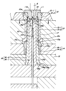
releasing tool. As shown in Fig. 2, an end portion-molding mold unit 1-2
comprises an end disc 11 as an upper portion-molding mold unit having an
injection opening lla to which the nozzle 6 of the injection molding device is
fitted and a mouth-molding mold unit 12 of a laterally split type which
surrounds and engages with the end disc and is adapted to mold a mouth
portion 10a of the cylindrical article 10.
The outer mold unit further comprises a barrel portion-molding unit
13 to which the mouth-molding mold unit 12 is detachably butted and which is
adapted to form a barrel portion of the cylindrical article, and a stopper
mold
unit 14 which is located under the barrel portion-molding unit 13 and butted
to
an end of the molding unit 13. The barrel portion-molding unit 13 and the
stopper mold unit 14 form the barrel portion and a bottom end face of the
cylindrical article, respectively. The barrel portion-molding unit 13 and the
stopper mold unit 14 are fixed and supported by a bottom disc 15 of the
molding mold. A member immediately under the bottom disc 1 S of the
molding mold is a stationary plate through which a knock-out pin is passed.
The barrel portion-molding mold unit 13, the stopper mold unit 14 and the
-12-
CA 02330554 2000-10-30
98822 (PCT/JP99/00986)
bottom disc 15 are provided with concentric inner cavities 13a, 14a and 15a,
respectively, through which the core 6 is introduced forwardly and rearwardly
from the lower side.
The molding inner cavity 14a of the stopper mold unit 14 is
designed as a plane tapered in section that is inclined outwardly in a
downward direction, and can closely contact a corresponding inclined face of
the core 16. The core is provided with a flange 16a at a lower end portion
thereof, which engages with a recess 15b of the bottom disc 15 of the molding
mold at a lower inner end portion to stop rise of the core 16. When the core
16 is completely inserted into the molding inner cavities 13a, 14a and 15a,
the
upper end of the core closely contacts the end disc 11 and the mouth portion-
molding mold unit 12 of the upper mold unit, so that a molding cavity is
defined between the core 16 and the mouth portion-molding mold unit 12 for
molding the mouth portion 10a of the cylindrical article and that a molding
cavity is formed between the core 16 and the molding inner cavity 13a of the
barrel portion molding mold unit 13 for molding the barrel portion of the
cylindrical article. Considering heat resistance, wear resistance, etc. in
molding the molten resin, each of the mouth portion-molding mold unit 12, the
barrel portion-molding mold unit 13, the stopper mold unit 14 and the core 16
comprises a surface portion (12-1, 13-1, 14-1, 16-1) made of a heat-resistance
and wear-resistant alloy and a main body (12-2, 13-2, 14-2, 16-2).
At an interface at which the upper end face of the core 16 contacts
the lower face of the end disc 11 of the upper mold unit are radially formed
runner grooves 18 into which the molten resin injected through the nozzle 6 of
the injection molding device is distributed. Taper-like thinned gate holes 19
are provided in a tip end portion of the core such that the gate holes extend
from the runner grooves 18 and communicate with the molding cavity 17 (See
Fig. 3 as a sectional view of Fig. 2 along III-III). The gate hole 19 is
inclined
-13-
CA 02330554 2000-10-30
98822 (PCT/JP99/00986)
to reach a gate opening 19a which is opened at a position that is under a
portion of the molding cavity for the mouth portion 10a of the cylindrical
article and axially inwardly separated from the upper end of the insert 32
arranged at the inner peripheral surface of the molding cavity.
A pin hole is provided axially in a central portion of the core 16
from an upper end to a lower end thereof, and communicates with the injection
opening 11 a of the end disc 11. The pin hole comprises a small-diameter
hole portion, an intermediate-diameter hole portion and a large-diameter hole
portion from upper to lower sides in this order. A knock-out pin 23, which
comprises a small-diameter portion 23a and a large-diameter portion 23b, is
closely and slidably fitted into the pin hole such that the small-diameter
portion 23a and the large-diameter portion 23b are located in the small-
diameter hole portion and the large-diameter hole portion, respectively.
An article in which the insert 32 is insertion-molded at a surface of
a thin cylindrical molded body 10 is obtained with use of the above-
constructed molding mold by injection molding as follows.
First, the mouth portion-molding unit 12, which is a split mold unit
for molding the mouth portion 10a of the cylindrical article 10 is closed from
right and left sides and connected with respect to the upper end face of the
barrel portion-molding mold unit 13, which is the pull-out mold unit having a
cylindrical inner face. Then, the end disc 11 of the upper molding mold unit
which engages with the nozzle of the injection molding device is fitted to the
mouth portion-molding mold unit, and the cylindrical stopper mold unit 14 is
fitted to the lower end portion of the barrel portion-molding unit 13.
Thereby,
the outer mold unit 1 of the molding mold is formed.
Next, as shown in Fig. 4, a thin insert 32 such as a label, which is
rounded in a cylindrical or conical shape, is inserted into an appropriate
position in the barrel portion-molding mold unit 13 of the outer mold unit 1
- 14-
CA 02330554 2000-10-30
98822 (PCT/JP99/00986)
from a lower opening of the stopper mold unit 14 by hands or any other
appropriate means, and then released. Consequently, since the outwardly
opened gentle taper face is formed at the inner face of the stopper 14, the
insert 32 is held at the inner face of the outer mold unit 1 along the taper
surface in the state that the insert is extended slightly outwardly in a
frusto-
conical shape along the above taper surface.
At that time, the insert 32 such as the label is inserted such that a
joint end face 12a of both sides of the insert 32 may not be coincident with
the
gate opening 9a of the gate hole 9 directed toward the upper end of the
core 16.
In this way, when the core 16 as the inner mold unit is moved
forwardly into the barrel portion-molding mold unit 13 of the outer mold unit
from the lower opening of the stopper mold unit 14 in the state that the
insert
32 is held at the inner surface of the barrel portion-molding mold unit 13 of
the outer mold unit, the core 16 closely contacts the inner surface of the
insert
32, and pushes the insert into the barrel portion-molding mold unit 13. When
the tip portion 16a of the core 16 is advanced and contacts the end disc 11 of
the upper molding mold unit, the insert 32 is extended to closely fit to the
inner surface of the outer mold unit. Consequently, a molding cavity 17
having a small gap is formed between the outer mold 1 and the core 16 for the
formation of the thin cylindrical body 10, and the molding mold is now closed
as shown in Fig. 2.
As mentioned above, the insert 32 is pushed along the inner surface
of the mold unit with a frictional force upon contacting the outer surface of
the
core 16, and the tip portion 16a of the core 16 contacts a cylindrical head-
forming portion of the molding unit 12 for the formation of the mouth portion
10a of the cylindrical body 10. Simultaneously, the lower end portion
contacts the end portion of the stopper mold unit 14, so that the core fits
into
-15-
CA 02330554 2000-10-30
98822 (PCT/JP99/00986)
the outer mold unit 1 to close the molding mold. Accordingly, even the thin
insert such as label in a frusto-conical shape can be accurately set as shown
in
Figs. 2 and 6 without being bent or wrinkled, which enables insertion molding.
The nozzle 6 of the injection molding device is fitted to the
injection opening 11 a of the end disc 11 of the molding mold in the state
that
the molding mold is closed in this manner and that the knock-out pin 23 is
located at a position shown in Fig. 2, and then the molten resin is injected
into
the molding cavity 17 through the nozzle 6 by driving an injection screw of
the injection molding device not shown. At that time, the molten resin
injected flows the gate holes 19 through the runner grooves 18, and is
injected
into the cavity of the molding mold through the gate openings 19a.
More specifically, as shown in Fig. 5, the molten resin flows into
the cavity through the gate openings 19a that is opened at a location axially
inwardly spaced from the upper end 12a of the insert 32 under the mouth
portion 10a of the cylindrical article 10, and while the molten resin flow
pushes the insert 32 set in the cavity to the inner surface of the barrel
portion-
molding mold unit l 3 of the outer mold unit, the flow is distributed to a
mouth
portion side and a lower end portion to fill the cavity. As a result, the
molten
resin is molded integrally with the insert. Thus, the molten resin does not
flow onto the front side of the insert 32.
After the molten resin is cooled and cured, following the injection
molding, the molding mold is opened to remove the article.
First, simultaneously with retracting the injection molding device
from the mold, the end disc 11 of the upper molding mold is moved rearwardly
to disengage the core 16 from the mouth portion-molding unit 12. Then, the
split mold unit of the mouth portion-molding mold 12 is opened to right and
left, and then the barrel portion-molding mold unit 13 is upwardly moved,
thereby exposing the outer face of the cylindrical article 10. See Fig. 6.
- 16-
CA 02330554 2000-10-30
98822 (PCT/JP99/00986)
Next, as shown in Fig. 6, the knock-out pin 23 is upwardly moved
to knock a runner end 18b, so that a cured resin piece inside the gate
openings
is separated and pushed away from the gate holes inside the gate openings
with the resulting impact force. A the same time, the lower end portion lOc
of the cylindrical article 10 is pushed up by upwardly moving the stopper
mold unit 14. By so doing, the cylindrical article is released from the outer
peripheral surface of the core, and discharged outside the molding mold in the
form of an insert-bonded cylindrical molded article as shown in Fig. 7.
As shown in Fig. 7, the cylindrical molded article has the label 32
bonded to the entire surface of the barrel portion, excluding the mouth
portion
10a thereof. Completely no resin is attached to the surface of the label, or
no
wrinkle is recognized thereon. A slight mark lOb of the gate opening only is
recognized at the rear side of the cylindrical article 20 at a location
deviated
from a butted end face 32b of the label.
As explained above, according to the present invention, the insert
such as label is integrated with the thin cylindrical article having almost no
escape taper surface by the insertion injection molding method, and the
injection gate opening of the molding mold is provided in the cylindrical
article-molding portion at the position slightly inwardly spaced from the end
portion of the insert and inward from the opposite side portions thereof, and
the molten resin is injected into the cavity through the gate opening and
insertion-molded therein. By so doing, the molten resin is insertion-molded
in the state that the insert such as the label is pushed and closely fitted to
the
inner surface of the outer mold unit with the pressure of the resin.
Therefore,
the molten resin is prevented from going onto the surface of the label.
It is essential to set the label or the like in the cavity such that the
end face or the butted face of the opposite end portions of the insert such as
the cylindrical label may not be coincident with the gate opening of the core.
-17-
CA 02330554 2000-10-30
98822 (PCT/JP99/00986)
If the insert is set in such a state that the end face or the butted face of
the
opposite side portions of the label or the like is coincident with the gate
opening of the core, this is likely to produce an unacceptable article through
the injected molten resin entering between the surface of the label and the
inner surface of the outer mold unit through the end face of the insert.
Since the outer mold unit and the core for the formation of the
barrel portion of the cylindrical body are constituted as the cylindrical
split
structure in the molding mold according to the present invention, no parting
line of the molding mold is formed on the surface of the molded article.
Further, the molding cavity for the formation of the thin cylindrical body is
defined between the cylindrical outer mold unit and the columnar core inserted
therein. Therefore, when the thin insert such as the label is inserted in a
cylindrically rounded shape into a middle portion of the outer mold unit and
the core is then inserted into the outer mold unit, the insert is contacted
and
held at the surface of the core, pushed into the cavity, and set at the
predetermined position. Therefore, the insert can be easily set, without being
needed to be set by using a special means for feeding the label or the like as
in
the prior art.
When the molding method according to the present invention is used,
a film or the like in which printing has been separately effected may be used
as
the insert such as the label. Therefore, the insert may be preliminarily
printed by offset printing, gravure printing or the like. Further, the present
invention is also suitable for a case using a metallic surface treatment with
gold, silver or the like in combination. As compared with a case where the
molded body is directly printed, almost no deviation occurs in the indicating
location.
As mentioned above, the present invention has the following
effects.
- 18-
CA 02330554 2000-10-30
98822 (PCT/JP99/00986)
The sheet-shaped insert-bonded cylindrical article comprises a
cylindrical molded body, and an insert bonded to an outer peripheral surface
of
a barrel portion of the cylindrical molded body on molding, wherein a mark of
an injection gate opening is positioned at an inner peripheral surface of the
cylindrical molded body while being inwardly apart from an upper end of the
insert in an axial direction and at a position corresponding to an inner
portion
of the insert as viewed in width directions from opposite sides of the insert.
Therefore the article has excellent appearance. Further, if a laminated film
is
used as the insert, the insert-bonded cylindrical molded article having
excellent light-shielding property and gas barrier property can be obtained.
According to the method for insertion molding the insert-bonded
cylindrical article, the insert is fitted, closely attached and held along the
inner
peripheral surface of the outer molding unit having the cylindrical pull-out
mold unit in the molding cavity defined between the outer mold unit and the
core inside the injection molding mold, the molten resin is injected, through
the injection gate opening provided in the core, toward the inner peripheral
surface of the molded body at a position inwardly apart from an upper end of
the insert in an axial direction and corresponding to an inner portion as
viewed
in width directions from opposite sides of the insert, the cylindrical molded
body is cured and formed while the insert is being pushed onto the inner
peripheral surface of the outer molding unit with the molten resin. Therefore,
the molten resin does not flow onto the outer surface of the insert or
wrinkled,
if the insert is strongly attracted onto the surface of the cavity under
vacuum as
in the prior art. Therefore, the insertion molding is possible with respect to
the thin insert.
The apparatus of the present invention for molding an insert-
bonded cylindrical article comprising a cylindrical molded body and an insert
integrally bonded to an outer peripheral surface of a barrel body of the
-19-
CA 02330554 2000-10-30
98822 (PCT/JP99/00986)
cylindrical molded body, said apparatus comprising an outer mold unit having
a cylindrical pull-out mold unit and defining a core-inserting space therein,
a
core to be inserted into the core-inserting space of the outer molding unit
from
one end thereof and to define a molding cavity between an inner peripheral
surface of the core-molding space, and a releasing tool for releasing the
shaped insert-bonded cylindrical article from the mold, the outer molding unit
comprising a barrel portion-molding mold unit having said core-inserting
space and an end portion-molding mold unit to be engaged with the barrel
portion-molding mold unit at the other end of the outer mold unit, having a
molten resin-injecting opening and being capable of moving outside from an
end portion, and the core having a gate hole communicating with the molten
resin-injecting opening at one end, having the other end that is at the outer
peripheral surface of the core and axially inwardly from the end portions of
the insert fitted along the outer peripheral surface of the core-inserting
space
and at an inner portion of the insert located inwardly from both width sides
of
the insert. In addition to the above-mentioned effects, the molding apparatus
according to the present invention in which the outer mold unit of the molding
mold has the fundamental structure of the cylindrical pull-out structure, not
the
split structure, for insertion molding with the insert such as the label, has
the
advantages that the article having beautiful appearance with no parting line
appears at the surface of thereof can be obtained, while its rigidity is
enhanced
to reduce the amount of the resin.
-20-