Note: Descriptions are shown in the official language in which they were submitted.
CA 02330632682 2000-08
WO 99/44308 PCT/US98/27881
1
DELAY COMBINER SYSTEM
FOR CDMA REPEATERS AND LOW NOISE AMPLIFIERS
FIELD OF THE INVENTION
The invention relates to the field of communications repeater systems. More
particularly, the invention relates to a CDMA repeater system having receive
signal
diversity, as well as multiple diversity delay combining low noise
amplification systems
which provide receive diversity dimensionality to conventional repeaters and
base
station receiver systems.
BACKGROUND OF THE INVENTION
Code division multiple access (CDMA) techniques are commonly used in
communication systems, to allow communications between a large number of
system
users. Repeaters are used as an extension between mobile users and base
stations in a
variety of communication systems. Tower-top amplifiers are also used as an
extension
of many base station and repeater designs.
K. Gilhousen, R. Padovani, and C. Wheatley, Method and System for
2 0 Providing a Soft Handoff in Communications in a CDMA Cellular Telephone
System,
U.S. Patent No. 5,101,501 (31 March 1992) disclose a system for directing
communications signals between a mobile user and cell sites, as the mobile
user moves
between cell site service areas.
K. Gilhousen, R. Padovani, and C. Wheatley, Diversity Receiver in a CDMA
Cellular Telephone System, U.S. Patent No. 5,109,390 (28 April 1992) disclose
a
spread spectrum receiver subsystem for utilization in a CMDA cellular
telephone
system.
D. Reudink, Narrow Beam Antenna Systems with Angular Diversity, U . S .
Patent No. 5,563,610 (08 October 1996) discloses a receiving system which
includes at
3 0 least one antenna providing a plurality of antenna beams. A first antenna
branch
processes a first plurality of signals within a first plurality of antenna
beams. The first
processing branch includes a plurality of delay paths, each receiving one of
the first
plurality of signals. The first processing branch also includes a combiner for
combining the signals after output from the delay paths. A second antenna
branch
3 5 processes a second plurality of signals within a second plurality of
antenna beams. The
second processing branch includes a plurality of delay paths, each receiving
one of the
second plurality of signals. The second processing branch also includes a
combiner for
combining the signals after output from the delay paths. A CDMA receiver has a
first
CA 02330632682 2000-08
WO 99/44308 PCTNS98/27881
2
port coupled to an output of the first processing branch, and a second port
coupled to an
output of the second processing branch.
R. ,Dean, F. Antonio, K. Gilhousen, and C. Wheatley, Dual Distributed
Antenna System, U.S. Patent No. 5,533,011 (02 July 1996) disclose a
distributed
antenna system for "providing multipath signals which facilitate signal
diversity for
enhanced system performance. Each node of the antenna at a common node
provides a
path having a different delay to the base station". While a "direct"
connection is
established between a distributed antenna system and a base station, wherein
the
distributed antenna system provides multipath signals (increasing the
dimensionality) to
facilitate signal diversity, the system does not disclose the use of diversity
within a
repeater system.
R. Dean, P. Antonio, K. Gilhousen, and C. Wheatley, Dual Distributed
Antenna System, U.S. Patent No. 5,513,176 (30 April 1996) disclose a
distributed
antenna system that is utilized in a system for "providing multipath signals
which
facilitate signal diversity for enhanced system performance. Each node of the
antenna
comprises more than one antenna. Each node at a common node provides a path
having
a different delay to the base station".
While prior art diversity techniques are typically used to expand system
capacity, they fail to disclose the use of diversity within the primary
antenna of a
2 0 CDMA repeater or a tower-top amplifier.
While the prior art discloses the use of diversity for in-building
applications
relative to a base station, they fail to disclose delay techniques to provide
diversity
within an over-the-air CDMA repeater.
The disclosed prior art systems and methodologies thus provide basic
2 5 distributed antenna systems, but fail to provide a diversity within a CDMA
receive
diversity system within an over the air repeater system, and also fail to
provide delay
combining diversity for a tower top or low noise amplification system. The
development of such a repeater system would constitute a major technological
advance.
3 0 SUMMARY OF THE INVENTION
Signal delay and combining techniques are used with multipath signals to
provide signal diversity gain within CDMA over-the-air repeater and low noise
amplifier systems. An incoming signal, such as from a remote user, is
typically
3 5 processed through two processing paths, wherein one processing path adds a
delay to
the processed signal. The two signal paths are then combined and preferably
filtered
through a sharp band pass filter, preferably a SAW filter. In an over the air
repeater,
the filtered signal is retransmitted towards a CDMA rake receiver at a base
station,
which processes the multipath signal to produce a clean signal representation.
In a low
CA 02330632682 2000-08
WO 99/44308 PCTNS98/27881
3
noise amplifier, the filtered signal is transferred directly into a base
station or repeater.
The preferred use of SAW filters protects the latter stages of the low noise
amplifier,
and also protects base stations from out-of-band signal interference. A
quadruple
diversity delay combining low noise amplification system for direct connection
to base
stations is also disclosed, which increases the receive diversity
dimensionality (the
number of receive paths) from two to four.
BRIEF DESCRIPTION OF THE DRAWINGS
Figure 1 shows a multipath input signal having a plurality of decorrelated
signal
paths received by a CDMA antenna system;
Figure 2 shows the interaction between a CDMA repeater and a base station;
Figure 3 is a block diagram of a dual diversity delay combining low noise
amplifier system for use in association with a conventional (non-diversity)
repeater to
provide receive diversity;
Figure 4 is a detailed view of a two stage band pass filter cascade:
Figure S is a detailed block diagram of a CDMA repeater system;
Figure 6 is a block diagram of a secondary growth enclosure for a second
CDMA Garner;
2 0 Figure 7 is a block diagram of a quadruple diversity delay combining low
noise
amplifier system for base stations;
Figure 8 is a first alternate embodiment of a diversity repeater, which has
two
separate complete repeater paths up to the output of the reverse power
amplifier;
Figure 9 is a second alternate embodiment of a diversity repeater, which has
two
2 5 separate complete repeater paths utilizing two donor antennas; and
Figure 10 is a third alternate embodiment of a diversity repeater, which has
two
separate complete repeater paths through the channel selective filter.
DETAILED DESCRIPTION OF PREFERRED EMBODIMENTS
Figure 1 shows an antenna assembly 15, and its interaction with an incoming
signal 12. The antenna assembly 15 consists of a plurality of antennas 16a -
16n, each
of which are connected to antenna inputs 17. The incoming signal 12 is a
fading signal,
meaning that the amplitude of the signal is rapidly changing due to
propagation effects.
3 5 This signal 12 is can be received simultaneously by a plurality of
antennas 16a-16n.
The instantaneous amplitude of the signal 12 at any given point in space {in
this case the
space that is occupied by the antenna assembly 15) will be different from the
instantaneous amplitude at any other point in space. The instantaneous
amplitude at any
given point is space is also dependent on the polarization of each antenna 16,
and the
CA 02330632682 2000-08
WO 99/44308 PCT/US98/27881
4
direction that each antenna 16 is pointed. This is shown in Figure 1 as a
fading signal
12, consisting of a plurality of signals 12a-12n. The instantaneous amplitude
of the
fading signals 12a-12n are generally different. This relationship between the
signals
12a-12n is called decorrelation.
The antennas 16a-I6n are configured such that the fading processes affecting
the signals received by each antenna 16 are not correlated. That is, the
signals 12
received on each individual antenna 16a-16n fade independently of the signals
on the
other n-1 antennas 16. When this relationship exists between a set of signals
12, they
are said to be mutually decorrelated. The antennas 16a-I6n must be configured
so that
this mutual decorrelation exists between the signals 12. There are many
different ways
to configure the plurality of antennas 16a-16n such that the mutually
decorrelated
relationship exists between the signals 12a-12n. Any configuration which
achieves this
relationship is acceptable.
As described above, the instantaneous amplitude of the signals 12a-12n is a
function of position, polarization, and arrival direction. Thus spatial
separation,
polarization separation, angular separation, or any combination of these, can
be used to
provide signals 12a-12n which possess the mutually decorrelated relationship.
Two common techniques for achieving mutual decorrelation in a mobile radio
environment are spatial separation and polarization separation, which take
advantage of
2 0 the fact that position and polarization separation provide decorrelated
signals. When
spatial separation is used to provide decorrelated signals, the antennas 16
must typically
be separated by 10-20 wavelengths to achieve satisfactory decorrelation. When
polarization separation is used, the antennas 16 are polarized such that the
polarization
between the antennas 16 is orthogonal.
2 5 In a CDMA system, a demodulator is used to optimally combine these signals
12a-12n into a composite signal, which is much more robust than any one of the
individual signals I2a-12n. This process of receiving multiple decorrelated
signals and
combining the signals 12a-12n is called receive diversity. Since the composite
signal is
more robust, than the individual received signal 12a-12n, the signal to noise
ratio
3 0 requirement for proper system performance is smaller than that required by
a system
that does not use receive diversity techniques. This reduction in signal to
noise ratio
increases the capacity of CDMA systems, and increases the range of CDMA
repeaters
and base stations.
The signal delay and combining techniques can be used within either a CDMA
3 5 over-the-air repeater, or a dual diversity delay combining low noise
amplification
system 46 (FIG. 3) to provide receive diversity to a conventional CDMA over-
the-air
repeater. The disclosed techniques can also be used within a quadruple
diversity delay
combining low noise amplification system 150 (FIG. 7) to further increase the
receive
diversity dimensionality.
CA 02330632682 2000-08
WO 99/44308 PCT/US98/27881
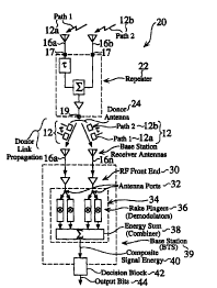
Base Station Multipath Demodulator. Figure 2 shows the reverse path
interaction 20 between a repeater 22 and a base station 39. The multipath
signal 12,
having decorrelated paths 12a and 12b, is transmitted toward the base station,
where it
is processed and eventually demodulated by a multipath demodulator, usually a
rake
5 receiver 34.
The antennas 16 used in the present invention can either be orthogonal in
polarization, or they can be spatially separated, typically by 10 to 20
wavelengths, to
provide the required decorrelation for diversity gain.
The reverse path (from a mobile station to a base station) uses a noncoherent
modulation scheme known as 64-ary orthogonal modulation. The base station 39
uses
a rake receiver 34 to demodulate the incoming signal 12. The rake receiver 34
demodulator is preferred for the multipath environment.
The rake receiver 34 simply adds the modulation symbol energy from each rake
finger 36, and processes a decision based on the total energy associated with
each
modulation symbol. This type of multipath demodulator 36, although not
optimal, is
only slightly less effective than an optimal multipath demodulator (several
tenths of a
dB). For more details regarding rake receiver design, refer to A.J. Viterbi,
CDMA
Principles of Spread Spectrum Communications, Addison-Wesley 1995.
The rake receiver demodulator 34 is accurately modeled as a maximal ratio
combiner, when the average signal power on the individual demodulator rake
fingers 36
are the same. This equivalence of inter-branch signal powers is typical for
most
embodiments of the present invention.
The maximal ratio combiner 38 combines the energy associated with each of the
incoming signal paths 12a,12b, effectively yielding the sum of the per finger
per bit
2 5 energy to noise density ratios, Eb/I0. The characteristic performance of
the maximal
ratio combiner 38 is given by:
Eb . Eb
~° ,.~~ 3' ~o
(1)
3 0 Eb represents the amount of energy associated with each information bit
(Joules), and
IO represents the noise plus interference power density (Watts/Hz). The ratio
(Eb/IO)i
represents the ratio of energy per information bit to noise plus interference
density, for a
single path 12.
The output 40 of the combiner 38 is the total per bit energy to noise density
ratio
3 5 (Eb/IO)Total~ The error rate of the system demodulator, for a fixed set of
channel
fading conditions and diversity configuration, is inversely proportional to
the total per
CA 02330632682 2000-08
WO 99/44308 PCT/US98/27881
6
bit energy to noise density ratio (Eb/IO)Total ~ The lower this ratio, the
larger the error
rate.
The. output 40 of the combiner 38 is fed to a decision device 42, which
estimates
which modulation symbol is sent. Once the modulation symbol is determined, the
actual information bits are derived.
The multipath demodulator 34 in one embodiment has four fingers 36, each of
which can track and demodulate a single path 12. One finger 36 is assigned to
each
available path 12. The rake receiver 34 can only differentiate paths 12 which
are either
on different RF branches, or those which are on the same RF branch but are
time
dispersed from each other. Paths 12 are typically associated with antennas 16.
Thus,
one rake finger 36 is typically locked onto each antenna 16.
The antennas 16 are configured to achieve a relationship of mutual
decorrelation
between the signals 12. There are numerous ways to configure the antennas 16
such
that the mutually decorrelated relationship exists among the signals 12. Any
configuration which achieves a relationship of mutual decorrelation among the
signals
12 is acceptable.
As described above, the instantaneous amplitude of the signals 12a-12n is a
function of position, polarization, and arrival direction. Thus spatial
separation,
polarization separation, or angular separation, or any combination of these,
can be used
to provide signals 12a-12n which possess a mutually decorrelated relationship.
The two of the most common techniques for achieving mutual decorrelation in
the mobile radio environment are spatial separation and polarization
separation, which
taking advantage of the fact that position and polarization separation provide
decorrelated signals. When spatial separation is used to provide decorrelated
signals,
2 S the antennas are typically be separated by 10 to 20 wavelengths, to
achieve satisfactory
decorrelation. When polarization separation is used, the antennas are
polarized such
that the polarization between the antennas is orthogonal.
The required total per bit energy to noise density ratio (Eb/IO)Total is
usually
specified for a given level of system performance under a set of predefined
conditions,
3 0 which include the correlation between paths 12a-12n, the number of paths
12a-12n, the
speed of a mobile user, and the channel conditions encountered. Almost always,
the
channel conditions are assumed to be a time dispersive channel, with an
amplitude that
is Rayleigh distributed. The speed of a mobile user is usually assumed to be
that
associated with the type of morphology the mobile user is operating in. The
correlation
3 5 between paths 12a,12n is almost always considered to be zero (independent
fading
paths). This leaves only the number of paths 12a-12n and the mobile speed as
the
factors which determine the total per bit energy to noise density ratio
(Eb/IO)Total~
CA 02330632682 2000-08
WO 99/44308 PCT/US98/27881
7
For a fixed speed of a mobile user, the (Eb/IO)Total requirement is simply a
function of the number of paths. For example, in suburban morphology with one
path,
the (Eb/IO)Total requirement for a 1 % error rate, is 14 dB. For two paths the
(Eb~O)Total requirement is 10 dB, and for four paths it is 9 dB. The reduction
in the
(Eb~O)Total is attributed to the diversity gain associated with the
introduction of
additional paths for demodulation. Since a typical base station 39 has at
least two
antennas 16; there is always a minimum of two paths (independent fading paths)
to
demodulate. Thus, for the worst case, the (Eb/IO)Total requirement is 10 dB.
For a conventional repeater configuration, there is only a single path 12
returned
to the base station 39 for demodulation. As shown in the example above, the
(Eb~O)Total required is 14 dB, which is 4 dB larger than the (Eb/IO)Total
required for
operation on the base station 39. This, however, is not an optimal
configuration for a
repeater, since the required (Eb/IO)Total can be reduced by providing a second
independent fading path for demodulation. The use of a second independent
fading
path reduces the required (Eb/IO)Total to 10 dB, which is the same as that
required for
operation on a base station 39.
The present invention effectively provides a second path 12b for the base
station
rake receiver 34 to demodulate. This allows the performance of the repeater 22
to be
optimal. In the case where the repeater 22 provides the second path 12b to the
base
station 39, the required (Eb/IO)Total is exactly the same as the base station
39, which is
10 dB.
In a basic embodiment of the present invention, two decorrelated signal paths
12a,12b are captured (with two antennas 16), which are both fed back to the
base
station rake receiver 34, over a single RF channel. The process used to
accomplish this
2 5 is a delay combining process, which time multiplexes the two decorrelated
signals, by
introducing a greater delay to one of the paths 12a or 12b as compared to the
other. The
time delay introduced to one of the paths 12a or 12b is large enough, such
that the
signals are no longer coherent. The excess delay is more than two chips, and
the
resulting code offset ensures that the cross correlation between the two paths
12a,12b is
3 0 zero. Thus the two paths 12a,12b will appear as noise to each other.
Since these two paths 12a,12b are dispersed in time, the rake receiver 34 is
able
to lock onto and demodulate both paths 12a,12b, to provide the desired
diversity gain.
The process used by the rake receiver 34 to find the two paths 12 comprises
the
following steps:
i) finding the time of arrival (TOA, relative time delay) and locking onto one
of
the paths 12a (usually the earliest one);
CA 02330632682 2000-08
WO 99/44308 PCT/US98/27881
8
ii) searching around the first path 12a (in time) for additional multipaths
12b-
12n;
iii) finding and locking onto the second path 12b; and
iv) demodulating the first 12a and second path 12b.
Thus the rake receiver 34 now has at least two decorrelated paths 12a,12b to
demodulate, and the required (Eb/IO)Total is the same as that of the base
station 39.
Dual Diversity Delay Combining Low Noise Amplification
System. Figure 3 is a block diagram of a dual diversity delay combining low
noise
amplification system 46 (tower mounted or otherwise), for use in association
with a
conventional (non-diversity) repeater, to provide receive diversity. The dual
diversity
delay combining low noise amplification system 46 is used to upgrade a
conventional
(non-diversity repeater) to a dual diversity repeater, by providing dual
branch diversity.
The dual diversity delay combining low noise amplification system 46 can
either be
mast mounted, or can be ground mounted near a conventional repeater.
The main attribute of the dual diversity delay combining low noise
amplification
2 0 system 46 is the delay combiner, which time multiplexes two receive paths
47a and 47b
onto one RF path 49. This capability allows a conventional repeater to
function as a
diversity repeater, when used in conjunction with the dual diversity delay
combining
low noise amplification system 46. Two antennas 16a and 16b are connected to
antenna connectors 17, and are implemented in a spatial and/or a polarization
diversity
2 5 configuration, to capture two decorrelated fading paths 12a,12b. The two
signals
associated with these paths are preferably fed directly from the antennas 16a,
16b into
band pass filters 48, which provide protection from adjacent band radio
signals. This
process is called preselection, and the band pass filters 48 are considered to
be
preselector filters 48.
3 0 In a preferred embodiment of the dual diversity delay combining low noise
amplification system 46, after the preselector filters 48, there are low noise
amplifiers
(LNAs) 56, which amplify the signal, in an effort to minimize signal to noise
reduction
in the later stages, especially the time delay element in the path associated
with the first
antenna 16a.
3 5 After the low noise amplifiers 56, the signal from the first antenna 16a
is fed to
a time delay element 58, and the signal from the second antenna 16b is
preferably fed to
a variable attenuator 60. The delay element 58, which is typically a SAW
device,
provides a differential delay to the signal from the first antenna 16a, as
compared to the
CA 02330632682 2000-08
WO 99/44308 PCT/US98/27881
9
second antenna 16b. The time delay allows the base station rake receiver 34 to
demodulate both paths I2a,12b, by displacing the paths 12a,12b in time. The
magnitude of the delay must be greater than 2 chip periods (e.g. approximately
1.8
microseconds for IS-95 and J-STD-008). The desired delay magnitude varies with
the
technology employed (e.g. wide band CDMA). On the second branch path 47b, a
variable attenuator 60 is preferably used to balance the gain between the
branches 47,
which is important for optimal system performance.
After the delay element 58 on the first branch 47a, and after the preferred
variable attenuator 60 on the second branch 47b, the signals 61a and 61b are
summed in
a combiner 62. The combiner 62 yields the power sum of the two processed
signals
6I. Since the processed signals 61a and 61b are time offset from each other by
more
than 1 chip, the signals 61 are no longer coherent. This is due to the nature
of the
pseudonoise (PN) code used to modulate the reverse path (up-link) signal.
This code is specifically designed to provide minimum correlation for a one
chip
or greater, offset. Since the processed signals 61a and 61b are no longer
coherent, they
interfere with each other on a random broad-band basis, thus creating a power
sum,
exactly the dame way noise powers sum. Both processed signals (displaced in
time)
appear at the output of the combiner 62, and either signal looks like noise to
the other
signal. In this example, this process reduces the signal to noise ratio by 3
dB.
2 0 However, this loss is gained back by the action of the rake receiver 34 at
the base
station 39.
Following the combiner 62, a low noise amplifier 64 is preferably used to
increase the signal level, in preparation for losses which can result in
latter stages. The
low noise amplifier 64 is also preferably used to maintain the signal to noise
ratio of the
2 5 signals.
The next stage in a preferred embodiment is a receive power splitter 66, which
provides an option of system expansion. The receive power splitter 66 is used
to split
the signal between two paths, one to the RXO/TXO port 67b, and one to the RX 1
/TX 1
port 67a. TI'~is configuration allows for the operation of two repeaters from
one dual
3 0 diversity delay combining low noise amplification system 46, which is a
preferred
method of system expansion. The duplex configuration, which is a conventional
antenna system configuration for repeater and base station systems, is defined
as the
use of a common antenna and cable for both receiving and transmitting, since
it
minimizes the number of antenna system components required.
3 5 In a preferred embodiment in which a receive power splitter 66 is used,
the
signal is fed from the two outputs of the receive power splitter 66 to two
separate two-
stage cascade filters 70a,70b. In an embodiment in which a receive power
splitter 66 is
not used, the signal is fed directly from the output of the low noise
amplifier 64 to a
single, two-stage cascade filter 70.
CA 02330632682 2000-08
WO 99/44308 PCT/US98/27881
Two stage cascade filters 70 are each comprised of a sharp receive band-pass
filter 72 and a RF switching filter 74, as shown in Figure 4. The two stage
cascade
filter 70 provides protection for the repeater from strong out of band
interference
signals, which are prone to cause intermodulation distortion (IMD). The two
stage
5 cascade filter 70 protects the repeater, by increasing the out-of-band input
intercept
point.
The two-stage cascade filter 70 is comprised of two filters. The first filter
is a
sharp pass-band filter 72 which provides protection from out-of-band
interference, as
described above. The second filter is a high power receive (Rx) band-pass
filter 74.
10 The Rx band-pass filter 74 provides protection to the sharp pass-band
filter 72 from
high power transmitter signals.
Placement of dual diversity delay combining low noise amplification system 46,
which in a preferred embodiment includes two-stage cascade filters 70, in
front of the
conventional repeater reduces the IIVVID contribution of the conventional
repeater to
1 S insignificant levels, leaving only the IMD products generated in the dual
diversity delay
combining low noise amplification system 46. This increases the out-of band
input
third order intercept point by 15 dB.
At this point in the dual diversity delay combining low noise amplification
system circuit 46, all the signal processing required for the receive system
to operate is
2 0 complete. An optional receive power splitter 66 is used in a preferred
embodiment, as
described above, to provide two outputs for system expansion. If the receive
power
splitter 66 is used, there are two filter cascades 70, one for each receive
power sputter
output. These filters, besides serving as a protection from interference, also
serve as
receive side duplex filters (carrier rejection filters). Cascade filters 70,
in conjunction
2 5 with preferred preselector filters 48 and TX band-pass filters 65, provide
the RF
switching and filtering required to operate in the duplex configuration.
The preferred duplex configuration allows for a single cable, which carries
both
transmitter and receiver signals, and is connected to either the RXO/TXO port
67b or the
RX 1/TX 1 port 67 a. The duplex configuration provides a bypass for the
transmitter
3 0 signals around the receiver's circuitry. The specific configuration shown
in Figure 3 is
a double duplexed configuration, since the signals are unduplexed at the donor
input/output ports 67a, 67b (bottom RXO/TXO and RX 1 /TX 1 ) and are then re-
duplexed
before the subscriber antenna ports 17.
Band-pass Filters. Band pass filters 48, 72, 103 are designed to attenuate
3 5 LO leakage, as well as any other spurious signals that result from the
mixing processes
that precede the band pass filter 48, 72, 103.
The SAW filter 72 preferably used in the dual diversity delay combining low
noise amplification system 46, as shown in Figure 4, is used to improve
intermodulation performance (increased out of band input intercept point).
CA 02330632682 2000-08
WO 99/44308 PCT/US98/27881
11
The,analogous preferred device in the repeater 22, 80 is the channel select
filter.
This filter provides the same effect, although its primary function is to
provide
individual channel selection (isolation), so that the repeater 22, 80 can
isolate and repeat
only the channel that the system operator desires.
Repeater. Figure 5 is a detailed block diagram of the primary enclosure
housing a CDMA repeater system 80. By using a repeater 80 to provide
diversity, a
single time multiplexed signal 12, consisting of at least two independent
fading paths
12a,12b, is transmitted to a base station 39, which typically includes a rake
receiver 34.
The rake receiver 34 at the base station 39 demodulates the time multiplexed
signal 12
consisting of at least two paths 12a,12b.
A repeater in a conventional CDMA system has only one input path or signal
branch, and has no signal diversity. As the single input path fades, there's
not a second
path there to pick up if the first one is down. The signal to noise
requirement, which
includes a fade margin, is large. This results in both a large link budget
loss and a
diminished sector capacity from a conventional repeater. The link budget for a
conventional repeater is reduced by 3 to 4 dB, and the sector capacity is also
reduced by
3 to 4 dB, when compared to a diversity repeater. These are significant
disadvantages
to conventional repeaters, particularly if the conventional repeater is used
to extend the
range of a sector, but fails to maintain capacity.
2 0 The wireless repeater 80 receives mobile signals from mobile users MS, and
does not act as a repeater between one stationary base station 39 and another
stationary
base station 39. The wireless repeater 50 is field based, and picks up mobile
signals,
acting like a base station or as an extension of a base station, using an over-
the-air
interface, in its own frequency. The wireless repeater 80 doesn't require
extra
2 5 spectrum, aid extends the effective service area of a cell site.
The diversity techniques employed in the present invention only work with
CDMA systems, since CDMA systems are able to recognize and demultiplex the
delay
imposed between the paths 12a,12b within the multipath signal 12.
The reverse path (up-link) operation of the repeater 80 is shown in figure 5 ,
3 0 wherein mobile subscribers MS send out signals 12 to the antenna assembly
15 on the
subscriber side (re-radiating side) of the repeater 81. A donor antenna
assembly 117 is
located on the donor side 119, to transmit processed signals to a base station
39. This
processed signal is received by antennas 16a and 16b at the base station 39.
On the
subscriber side 81, there is either a dual polarization antenna assembly 15,
or a spatially
3 5 separated vertically polarized antenna assembly, or any combination of
these two
schemes. The signals go through the diplexor 82, which acts as a filter to
separate the
transmit and, receive signals 12, into two low noise amplifiers 86. The first
low noise
amplifier 86, in conjunction with the delay element 96, comprise the reverse
path
diversity front end 92. The reverse path diversity front end 92 is used for
low noise
CA 02330632682 2000-08
WO 99/44308 PCTNS98/27881
12
amplification and signal delay. The reverse path main front end 84 is
comprised of a
low noise amplifier 86, a combiner 88, and a voltage controlled attenuator
I20. The
delay is added to the signal path associated with the reverse path diversity
front end 92,
as discussed above in relation to the dual diversity delay combining low noise
amplifier
system 46 for repeater applications. The gain differential is balanced between
the
reverse path main front end 84 and the reverse path diversity front end 92,
measured
between the input ports and the output of the combiner 88.
The paths I2a,12b are then summed 88 and are preferably fed to a channel
select filter 100, which has a sharp SAW filter to eliminate out-of band
signals. The
unwanted spurious signals and LO leakage at the output of the channel select
filter 100,
which result from signal conversion processes, are preferably filtered out by
a band
pass filter 103. The signal is then preferably sent through a power amplifier
102,
through a diplexor 82, and is then transmitted to the base station 39 through
donor
antenna assembly I 17. At this point, there are two paths 12a and 12b
separated in time,
as shown in Figure 1 and Figure 2. While the combined signal 12 is drawn
showing
two path elements 12a, I2b, the elements are not necessarily discrete.
On the forward direction (down-link) side of the circuit, a transmitted signal
12
comes from the base station 39 on the donor side 119, to the diplexor 82, and
is
separated out, wherein part of the signal 12 is directed through the forward
path front
2 0 end 85, which includes a low noise amplifier 86 and a voltage controlled
attenuator 90.
The signal is then directed through a channel select filter 100, a band pass
filter 103, a
forward power amplifier I06, a diplexor 82, and is then transmitted on the
subscriber
side of the repeater 80, on either of the antennas 16 of antenna assembly 15.
The combines 110 shown on the donor side 119 allows a second carrier reverse
2 5 path (up-link) transmit path to be added, while J 1 and J2 allow a second
CDMA RF
carrier path for the forward path (down-link). While the basic embodiment only
requires one carrier, a typical CDMA spectrum currently has a plurality of RF
carriers.
Therefore, alternate embodiments of the invention can use a plurality of
carrier transmit
paths.
30 System Advantages. The wireless repeater 80, such as a personal
communications services (PCS) repeater 80, provides many advantages over prior
art
repeater systems. The main advantage over the prior art is the reverse path
receive (up-
link) diversity feature. This feature improves system sensitivity and call
quality, and
maintains normal system capacity, which are significant improvements over the
prior
3 S art. The wireless repeater 80, which in a preferred embodiment is channel
selective, is
optimized for CDMA applications, is designed to have a low up-link noise
figure, and
high down-link transmit power that is close to base station power, with
diversity paths
in the up-link. The basic embodiment of the wireless repeater 80 is equipped
with one
CDMA frequency carrier. In an alternate embodiment of the repeater, a growth
CA 02330632682 2000-08
WO 99/44308 PCT/US98/27881
13
enclosure is included for a second CDMA carrier 130, as shown in Figure 6,
with J-
connections 118 between the first carrier 80 and the second carrier 130.
Repeater System Architecture. A block diagram for the primary enclosure
housing a first CDMA frequency carrier for the channelized air-to air wireless
repeater
80 is shown in Figure 5. The repeater 80 is typically connected, through
subscriber
antenna ports 17, to a single antenna assembly 15 on the subscriber side 81,
and to a
single donor antenna assembly 117, through donor antenna ports 19, on the
donor side
119. This minimizes the number of antennas required, and minimizes the visual
impact
of a given site, which is a major concern during site development processes.
The
repeater 80 is also considered to be non-translating, since it does not shift
the received
frequency to a different transmitter frequency for the re-radiated signal or
donor links.
Non-translating repeaters 80 are also known as on-frequency repeaters 80.
The diplexor 82 provides common access to a single antenna 15 for both uplink
and downlink signals. The isolation between the transmission (TX) and
reception (RX)
paths is sufficient to avoid both receiver overload and receiver
desensitization caused by
noise from the transmitter. The diplexor 82, as well as propagation losses,
provides
this isolation.
The main front end module (MFE) 84 can be used as the front end of the receive
path, for both uplink signals 12 and downlink signals 12. A combiner 88 is
included
after the preferred low noise amplifier (LNA) 86, to combine the delayed
diversity path
12. A combiner 86 is not required in the downlink circuitry. A voltage
controlled
attenuator (VCA) 90,120 is used for automatic level control (ALC), for
protection of the
repeater 80 against input overload conditions, and for calibration of the
overall gain.
The reverse path diversity front end (DFE) 92 is the front end of the reverse
2 5 path diversity circuitry 94. A delay element 96 is inserted after a
preferred low noise
amplifier 86, to provide at least two chip periods of time delay, for
discrimination of the
signal by the rake receiver 34. The output is preferably further amplified 56
to
compensate the loss, and is combined with the other receive signal via the
combiner 88
in the reverse path main front end 84.
3 0 In a preferred embodiment of the repeater 80, a channel select filter
(CSF) 100
tunes the local oscillator to a specific channel, downconverts the RF signal
to IF,
provides channel filtering, and then upconverts the signal back to RF. The
channel
select filter 100 also provides gain adjustment for the wireless repeater 80.
A preferred reverse power amplifier (RPA) 102 provides signal amplification
3 5 for the reverse path (up-link). Similarly, a preferred forward power
amplifier (FPA)
106 provides high power amplification for the forward path (down-link) 108.
An alarm control unit (ACU) 112 controls and monitors all the modules within a
preferred embodiment of the repeater 80. The alarm control unit 112 also
communicates with the network or local. craft via control software.
CA 02330632682 2000-08
WO 99/44308 PCT/US98/27881
14
As discussed above, a band pass filter 103 is used to filter out image and
local
oscillator signals at the output of the channel select filter 100, to avoid
radiation of
unwanted signals.
The power supply PS 116 provides direct current (DC) power to all modules.
A preferred network interface module 114 serves as an interface to the
network, for
alarm reporting, control, and monitoring. J-connections 118 are provided in
the growth
enclosure 130 for the second CDMA carrier.
In a preferred embodiment of the invention, a second CDMA carrier is added,
by connecting a growth enclosure to the primary enclosure of the repeater 80,
as shown
in the block diagram of Figure 6. The second carrier has its own forward power
amplifier 106b and reverse power amplifier 102b, to maintain the same downlink
transmit power as the first carrier 80.
Repeater Process. The basic repeater process comprises the following
steps:
i) receiving a signal 12 through a receiving antenna assembly 1 S from a
mobile
user, said signal having a plurality of uncorrelated signal paths;
ii) preferably processing said received signal 12 through a first signal
2 0 processing path and a second signal processing path, said second signal
processing path having a delay element 96;
iii) combining 88 said processed signal from said first signal amplification
path
and said second amplification path;
iv) ~ preferably processing said processed and combined signal through a
channel select filter (CSF) 100 and/or a band pass filter 103; and
v) transmitting said combined signal though a transmission antenna 117.
Alternate Embodiments for Diversity Repeater. There are other
possible delay combining embodiments for the diversity repeater, other than
the
preferred embodiment. Figure 8 shows a first alternate embodiment of a
diversity
repeater, which has two separate complete repeater paths up to the output of
the reverse
3 5 power amplifier. In this embodiment, the two paths are combined and
transmitted back
to a base station 39 via one donor antenna. One of the two paths introduces an
extra
1.8 microsecond delay. This delay is introduced easiest within the channel
select filter
(CSF) module 100. Figure 9 shows a second alternate embodiment of a diversity
repeater, which has two separate complete repeater paths utilizing two donor
antennas.
.._ _.,. a. . "., y vam vwi ll~lO W LG1111 IAlr.l'11 VAVI~r ~,~ ~!~ ~
_""., ".... ~ ~ ~ ~~ uuGi
One of the paths introduces an extra 1.8 microsecond delay,
Again, this delay is
introduced easiest within the channel select filter (CSC module
100. Figure 10 shows a
third alternate embodiment of a diversity repeater, which has ~
two separate complete
repeater paths through the channel selective filter. In this f,r,
embodiment, the two paths
are first combined, and then are transmitted back to the base '~
station, as in the preferred
1 U embodiment. One of these paths introduces an extra 1.B
microsecondm
delay. Again,
this delay is introduced easiest within the channel select filter
(CSF) module 100. While
the alternate embodiments of the diversity repeater are generallyo
functionally equivalent
to that of the preferred embodiment, they are generally more
expensive to implement.
Quadruple Diversity belay Combining Low Noise Amplification
System
150 for Base Stations 39. Figure 7 is a block diagram of a quadruple
diversity delay
combining low noise amplification system 150 for base stations
39 (tower-top
installations or otherwise). The quadruple diversity delay combining
low noise
amplification system 150 for base stations 39 is a system for
increasing the diversity
dimensionality of a base station 39 or microcell, from two branch
to four branch
?0 diversity.
The quadruple diversity delay combining low noise amplification
system 150 for
base stations 39 uses four antennas 16a-d in either a spatial
separation configuration,
a multiple polarization configuration, or a configuration that
combines these two
techniques, to capture four independent fading signals (paths)
12.
These four signals (paths) 12 are first filtered 48, and then
amplified with one or
more low noise amplifiers 56, to minimize signal to noise ratio
reduction in the following
stages.
A delay element 58 is used to delay the ~1 and ~3 paths, as
shown in E=Igure 7,
which are typically delayed by a minimum of two chip periods
(for one embodiment,
3U this is greater than 7.8 microseconds). This delay is added,
as described above, to
. allow for rake receiver demodulation of both paths. The paths
associated with ~1 and
~2 are then combined with a simple 3 dB combiner 62, as are
the paths associated with
~3 and ~4. Thus, the four paths are combined into two base station
antenna ports.
Preferred Low noise amplifiers 64 follow each combiner 62, which
are used to
overcome the loss of the following SAW filter ~2--(or other
sharp band pass filtering
device), in an effort to maintain signal to noise ratio.
This amplified signal is then preferably passed through a dual
band pass filter
cascade 70, comprising a SAW band pass filter 72 (or other sharp
band pass filtering
device) followed by another band pass filter 74, to protect
the low power SAW filter
from the transmitter's power. The dual band pass filter cascade
70, as discussed
above, is shown in Fgure 4. The purpose of the second band pass
filter 74 is to
attenuate the strong RF signal from the transmitter site of
the system, to protect the
CA 02330632 2000-08-03
WO 99/44308 PCT/US98/27881
16
SAW filter from the high power RF signal of the transmitter. The first band
pass filter
72 provides protection from out of band (out of receive band) interference
which can
result in the generation of intermodulation (IM) products. This protection
greatly
increases the "out of band input intercept point" of the tower top and base
station
cascade system configuration. Following the band pass filter cascade 70 is a
junction
point 152 where the receive and transmitter paths are coupled.
There is an additional path provided for the transmitter path, which comprises
a
band pass filter 65 and the appropriate coupling devices (junction points).
The
embodiment shown has two transmitter paths 53, one associated with the _1 and
4
receiver paths. This allows the quadruple diversity delay combining low noise
amplifier system 150 to operate in a dual duplex configuration, which uses one
antenna
for both transmit and receive functions (a common requirement for PCS and
cellular
operators).
The quadruple diversity delay combining low noise amplification system 150
1 S provides a significant increase in system reverse link sensitivity (4-5
dB), an increase in
system capacity (approximately 2 dB), and an improvement in reverse link frame
error
performance.
Although the delay combiner system and its methods of use are described herein
in connection with CDMA repeaters and delay combining amplification systems,
the
2 0 apparatus and techniques can be implemented within other communications
devicesand
systems, or any combination thereof, as desired.
Accordingly, although the invention has been described in detail with
reference
to a pauicular preferred embodiment, persons possessing ordinary skill in the
art to
which this invention pertains will appreciate that various modifications and
2 5 enhancements may be made without departing from the spirit and scope of
the claims
that follow.
CA 02330632 2000-08-03