Note: Descriptions are shown in the official language in which they were submitted.
CA 02330855 2000-10-30
.::: .: . r:.: . :..~~..~~>~r .~...~~.: ~.::: ~:::::::::::..::::
..,~.. .. . .:. :..::::.:~::::::.~:. .~::::::::::::....::: :.:::
:1..::'~~::~....r~..t.~...t'~....: :.:::::: .:::::::::.~::::::: ::.:.:
.:::
, ~, ~ :... . .. .. ..
.
.. .. .. . .. . . . . .
. . . . . . . ..
.
. , . . . . . . ... ...
. .
... .. ... .... .. ..
AUTOMA'~~CED IN OVO INJECTION APPARATUS
Field of the Invention
The present inve~ation relates to treatment of avian embryos and, more
particularly, relates to in ovo injection devices and methods for delivering
various
substances to live embryonated eggs.
Fiack~round of the Invention
Injections of various substances into avian eggs have been employed to
decrease post-hatch mortality rates, increase the potential growth rates or
eventual
size of the resulting chicken, and even to influence the gender determination
of the
embryo. Similarly, injecaions of antigens into live eggs have been employed to
incubate various substances used in vaccines which have human or animal
medicinal or diagnostic applications.
Examples of substances which have been proposed as viable treatment (or
harvestable vaccine material) alternatives for delivery via in vvo injection
of avian
embryos include live culture vaccines, antibiotics, vitamins, and even
competitive
exclusion media (a live replicating organism). Specific examples of treatment
substances are described in U.S. Pat. No. 4,458,630 to Sharma et al, and U.S.
Pat.
No. 5,028,421 to Frederic:ksen et al.
Conventionally, the physical injection has been typically targeted at
preferred positions withvz the egg in order to administer the substance into
specific
developing regions of thc: embryo. See, for example, U.S. Patent No. 5,a36,979
to
Paul et al., which describes an injection apparatus for accurate and precise
injection
of eggs of varying sizes. As understood by those of skill in the art, as the
incubation period progresses towards maturity (i.e., hatching), the embryo and
its
membranes, e.g., the air .cell, the allantois, and yolk sac, correspondingly
change in
both volume and position within the egg shell. Additionally, the quantitative
volume of the enclosed fluids vary as well; for example, the density of the
allantois
(fluid, solid) varies as a function of time over the incubation period.
SUBSTITUTE PAGE 1 ~ .:.
:::::::::::::::::::...:::::::..::..:>::..:::::::::::::: AitPcf~ <:
;:::;:::,;::......::, .,':::.::::;..:::..:::_:vv::vDED SHEET
... .. .
::P: ~..:: .:.:..:. =:~::~=a~~>::.~~d :.: >:::
CA 02330855 2001-03-21
Thus, selection of both the site and time of treatment can impact the
effectiveness of the injected substance as well as the mortality rate of the
treated
embryos. See e.g., U.S. Patent No. 4,458,630 to Sharma et al., U.S. Patent No.
4,681,063 to Hebrank, and U.S. Patent No. 5,158,038 to Sheeks et al.
Summary of the Invention
The present invention, recognizes that there is a need to introduce multiple
substances into a live egg with a minimum of trauma thereto, including
substances
which are effective treatment alternatives when separately injected but become
biologically noxious when combined. Thus, a first object of the present
invention is to
provide a multi-site in ovo injection device for delivering a variety of
treatment
substances to avian embryos while minimizing the risk of injury thereto.
Additionally, the present invention recognizes that there is a need to
withdraw
multiple samples from a live egg with a minimum of trauma thereto, including
withdrawing two samples from different compartments of, or locations in, the
egg at
the same time. Thus, a further object of the present invention is to provide a
multi-
site in ovo sampling device for withdrawing a variety of samples from avian
embryos
while minimizing the risk of injury thereto.
It is another object of an aspect of the present invention to introduce,
without
mixing, biologically incompatible products in ovo to embryos.
It is a further object of an aspect of the present invention to separately
introduce without mixing at least two different treatment materials into
different
locations in the egg, through either a single or two separate delivery paths.
It is another object of an aspect of the present invention to introduce at
least
two different treatment substances which are separately delivered by one or
more of
time and spatial separation into an opening in the egg shell.
These and other objects of aspects, advantages, and features are provided
by a multi-site or multi-dosage injection or withdrawal methods and apparatus
disclosed herein. The methods and apparatus of the invention deliver at least
two
different substances into predetermined areas within the egg, or withdraw
samples
from at least two different predetermined locations in the egg.
In particular, a first aspect of the present invention is a multi-injection
method
for treating avian embryos in ovo. In the method, an avian egg is oriented
-2-
CA 02330855 2000-10-30
WO 99/34667 PCT/US99/00572
into a predetermined position and a small first opening is introduced into the
shell
of the avian egg. A delivery device which has either a single or a plurality
of - -
lumens therein is extended through the first opening and into the egg a
predetermined depth. Predetermined dosages of a first substance and a second
S substance are separately release;d into the egg and the delivery device is
retracted
from the egg, thereby treating the avian embryo. Advantageously, a plurality
of
lumens can include separate needles that separately deliver the first and
second
substances to spatially separate .areas, or different compartments, of the
egg. In one
embodiment, a first needle extends longitudinally a greater distance in the
egg than
a second needle; alternatively, one or more of the needles can include a side
port to
dispense the substance transversely spatially separated from the other
substance.
Alternatively, the needles can t>e adapted to withdraw a sample of material
from
the egg.
Another aspect of the present invention includes a multi-injection method
for treating avian embryos i.n ovo that first orients an avian egg into a
predetermined position and then introduces a small first opening into the
shell of
an avian egg. Additionally, a ;;mall second opening is introduced into the
shell of
the avian egg, the second opening being spaced apart from the first opening.
Respective ones of the first and second delivery devices are extended through
:Z0 corresponding first and second openings and into the egg a predetermined
depth.
A predetermined dosage of a first substance and a second substance is released
from respective ones of the first and second delivery devices into the egg.
The
delivery devices are retracted from the egg, thereby treating the avian
embryo.
Alternatively, the delivery devices can be adapted as sampling devices, to
ZS withdraw a sample of material from the egg.
Yet another aspect of the present invention includes a multi-injection
method for treating avian embryos in ovo which orients an avian egg into a
predetermined position and introduces a small first opening into the shell of
an
avian egg. A delivery device is extended through the first opening and into
the egg
:SO a predetermined depth. Predetermined dosages of a first substance and a
second
substance are released into the egg and the delivery device is retracted from
the
egg, thereby treating the avian f;mbryo. Advantageously, this method
temporally
combines the different substances to minimize degradation of the substances
-3-
CA 02330855 2000-10-30
WO 99/34667 PCT/US99/00572
attributed to reactance thereberween. Thus, preferably, this method allows the
first
and second substances to be stored in separate chambers and temporally
combines
or mixes the first and second substances, either with an active mixing
chamber, or
by introducing them into a common delivery path, prior to delivery into the
egg.
An additional aspect of the present invention is directed towards an
automated in ovo injection apparatus. The apparatus comprises a fixture for
holding a plurality of eggs in a substantially upright and aligned position.
The
fixture is configured to provide external access to predetermined areas of the
eggs.
The apparatus also includes a plurality of injection delivery devices
configured to
contact predetermined areas of the egg; at least one of the injection devices
corresponds to each egg in the fixture. Each of the delivery devices comprises
a
first and second lumen that is adapted to be received into the egg. The
apparatus
further comprises a first treatment substance container for holding a first
treatment
substance. The first container is in fluid communication with each of the
plurality
of injection delivery devices. The apparatus also includes a second treatment
substance container for holding a second treatment substance. The second
container is in fluid communication with each of the plurality of injection
devices.
The first container and each of the plurality of injection devices defines a
first fluid
pathway therebetween. Similarly, the second container and each of the
plurality of
injection devices define a second fluid pathway therebetween. A pump is
operably
associated with the first and second containers and the injection units for
delivering
a predetermined dosage of each of the first and second treatment substances to
each
of the injection devices. Alternatively, the delivery devices can be adapted
to
withdraw a sample of material :from the egg, where the samples are maintained
in
separate fluid pathways.
Advantageously, various alternative embodiments of the injection and
sampling delivery devices allow for a multiplicity of convenient and useful
configurations. For example, the double lumens can be concentrically
configured
to be telescopically extended at different positions into the egg.
Alternatively, the
first and second lumens can be provided by a plurality of needles of differing
configurations, such as length, port position, and the like.
Another aspect of the present invention is also directed to an automated in
ovo injection or sampling apparatus. The apparatus comprises a fixture for
holding
-4-
CA 02330855 2006-O1-31
a plurality of eggs in an aligned position, such that the fixture is
configured to provide
external access to predetermined areas of the eggs. The apparatus includes a
plurality
of first injection delivery (or sampling) devices and a plurality of second
injection
delivery (or sampling) devices, each configured to contact predetermined areas
of the
egg, a respective one of each of the first and second injection delivery (or
sampling)
devices corresponding to one egg in the fixture. The device also includes
first and
second treatment substance containers for holding respective ones of first and
second
treatment substances (or first and second sample substance containers for
holding
respective ones of first and second samples withdrawn from the egg). The first
container is in fluid communication with each of the first injection delivery
devices
and the second container is in fluid communication with each of the second
injection
delivery devices. Thus, the first container and each of the first delivery
devices define
a first fluid pathway therebetween and the second container and each of the
second
injection delivery devices define a second fluid pathway therebetween such
that the
first pathway is separate from the second pathway. A pump is operably
associated
with the first and second containers for delivering a predetermined dosage of
each of
the first and second treatment substances to each of the respective first and
second
injection devices. Similar to the apparatus above, this device can be
alternatively
configured to deliver different treatment substances to (or withdraw different
samples
from) different treatment sites within the egg.
Eggs treated by the method of the present invention are preferably incubated
to hatch after the treatment substances are administered.
In accordance with one embodiment of the present invention, a mufti-injection
method for delivering substances to compartments of an avian egg, comprises
the
steps of:
orienting an avian egg into a predetermined position;
introducing a small first opening into the shell of the egg;
extending a delivery device through the first opening and into the egg a
predetermined depth;
releasing predetermined dosages of a first substance and a second substance
into the egg in separate locations therein; and
retracting the delivery device from the egg.
-5-
CA 02330855 2006-O1-31
In accordance with another embodiment of the present invention, a multi-
injection method for delivering substances to compartments of an avian egg,
comprises the steps of:
orienting an avian egg into a predetermined position;
introducing a small first opening into the shell of the avian egg;
introducing a small second opening into the shell of an avian egg, the second
opening being spaced apart from the first opening;
extending a first delivery device through the first opening into the egg a
predetermined depth and to a first location within the egg;
extending a second delivery device through the second opening into the egg a
predetermined depth and to a second location within the egg different from the
first
location;
releasing a predetermined dosage of a first substance from the first delivery
device into the egg;
releasing a predetermined dosage of a second substance from the second
delivery device into the egg; and
retracting the first and second delivery devices from the egg.
In accordance with another embodiment of the present invention, an
automated in ovo injection apparatus, comprises:
a flat for holding a plurality of eggs in a substantially upright and aligned
position, wherein the flat is configured to provide external access to
predetermined
areas of the eggs;
a plurality of injection delivery devices configured to contact the
predetermined areas of the eggs, at least one of the injection delivery
devices
corresponding to each egg in the flat, and each of the inj ection delivery
devices
comprising first and second lumens adapted to be received into the eggs;
a first treatment substance container for holding a first treatment substance,
the
first container in fluid communication with each of the first lumens;
a second treatment substance container for holding a second treatment
substance, the second container in fluid communication with each of the second
lumens;
at least one pump operably associated with the first and second containers and
-Sa-
CA 02330855 2006-O1-31
the injection devices and configured for delivering a
predetermined dosage of each of the first and second treatment substances to
each of the injection devices.
In accordance with another embodiment of the present invention, an
automated in ovo injection apparatus, comprises:
a flat for holding a plurality of eggs in an aligned position, wherein the
flat is
configured to provide external access to predetermined areas of the eggs;
a plurality of first injection delivery devices configured to contact
predetermined areas of the egg, one of the first injection delivery devices
corresponding to each egg in the flat;
a plurality of second injection delivery devices configured to contact
predetermined areas of the egg, one of the second injection delivery device
corresponding to each egg in the flat;
a first treatment substance container for holding a first treatment substance,
the
first container in fluid communication with each of the first injection
delivery devices;
a second treatment substance container for holding a second treatment
substance, the second container in fluid communication with each of the second
injection delivery devices;
a drive means operably associated with the first and second containers for
delivering a predetermined dosage of each of the first and second treatment
substances to each of the respective first and second injection devices.
In accordance with another embodiment of the present invention, an
automated in ovo inj ection apparatus, comprising:
a flat for holding a plurality of eggs in an aligned position, wherein the
flat is
configured to provide external access to predetermined areas of the eggs;
a plurality of injection delivery devices, at least one of the injection
delivery
devices corresponding to each egg in the flat, each of the devices having
opposing
first and second end portions, the second end portion having an end port
configured to
contact and penetrate into a predetermined location in the egg;
a first treatment substance container for holding a first treatment substance,
the
first container in fluid communication with each of the injection delivery
devices;
a second treatment substance container for holding a second treatment
-Sb-
CA 02330855 2006-O1-31
substance, the second container in fluid communication with each of the
injection
delivery devices;
a pump operably associated with the first and second containers for delivering
a predetermined dosage of each of the first and second treatment substances to
each of
the injection devices, wherein the predetermined dosages of the first and
second
treatment substances are combined prior to the end port to be delivered to the
egg
together at the site of injection.
In accordance with another embodiment of the present invention, a method for
delivering substances to compartments of an avian egg, comprises the steps of
orienting an avian egg into a predetermined position;
introducing a small first opening into the shell of the egg;
extending a delivery device through the first opening and into the egg a
predetermined depth;
releasing a predetermined dosage of a substance into a first location of the
egg;
removing a sample from a separate second location of the egg; and
retracting the delivery device from the egg.
In accordance with another embodiment of the present invention, a method for
removing samples from an avian egg, comprises the steps of
orienting an avian egg into a predetermined position;
introducing a small first opening into the shell of the egg;
extending a sample removal device through the first opening and into the egg a
predetermined depth;
removing first and second samples from the egg in respective first and second
separate locations therein; and
retracting the sample removal device from the egg.
In accordance with another embodiment of the present invention, a method for
delivering substances to compartments of an avian egg, comprises the steps of
orienting an avian egg into a predetermined position;
introducing a small first opening into the shell of an avian egg;
introducing a small second opening into the shell of an avian egg, the second
opening being spaced apart from the first opening;
extending a delivery device through the first opening into the egg a
-Sc-
CA 02330855 2006-O1-31
predetermined depth and to a first location within the egg;
extending a sample removal device through the second opening into the egg a
predetermined depth and to a second location within the egg different from the
first
location;
releasing a predetermined dosage of a substance from the delivery device into
the egg;
removing a sample from the egg second location via the sample removal
device; and
retracting the delivery device and sample removal device from the egg.
In accordance with another embodiment of the present invention, a method for
removing samples from an avian egg, comprises the steps of:
orienting an avian egg into a predetermined position;
introducing a small first opening into the shell of the avian egg;
introducing a small second opening into the shell of the avian egg, the second
opening being spaced apart from the first opening;
extending a first removal device through the first opening into the egg a
predetermined depth and to a first location within the egg;
extending a second removal device through the second opening into the egg a
predetermined depth and to a second location within the egg different from the
first
location;
removing a first sample from the first location;
removing a second sample from the second location; and
retracting the first and second sample removal devices from the egg.
In accordance with another embodiment of the present invention, an
automated in ovo injection apparatus, comprises:
a flat for holding a plurality of eggs in a substantially upright and aligned
position, wherein the flat is configured to provide external access to
predetermined
areas of the eggs;
a plurality of injection delivery devices configured to contact predetermined
areas of the egg, at least one of the injection devices corresponding to each
egg in the
flat, each of the delivery devices comprising first and second lumens adapted
to be
received into the egg;
-Sd-
CA 02330855 2006-O1-31
a first container for holding a treatment substance, the first container in
fluid
communication with each of the first lumens;
a second container for receiving a sample from each egg, the second container
in fluid communication with each of the second lumens;
at least one pump operably associated with the first and second containers and
the injection devices and configured for delivering a predetermined dosage of
the
treatment substance to each of the first lumens and for removing a sample from
each
egg via each of the second lumens.
The foregoing and other objects of aspects of the present invention are
explained in detail in the specification set forth below.
Brief Description of the Drawings
Figure 1 is a partial front view of a mufti-site injection apparatus according
to the present invention.
Figure 2 is side perspective view of a mufti-site injection apparatus shown in
Figure 1.
Figure 3 is an enlarged section view taken along line 3-3 in Figure 2
illustrating one embodiment of a mufti-site inj ection head according to the
present
-Se-
CA 02330855 2000-10-30
WO 99/34667 PCT/US99/00572
invention.
Figure 4 is an enlarged view of the injection head in Figure 3 with lumens --
shown downwardly extended and delivering substances into an egg, according to
one embodiment of the present invention.
S Figure 5 is an enlarged sectional view of the lumens shown in Figure 4.
Figure 6 is an end view taken along lines 6-6 in Figure 5.
Figure 7 is an enlarged partial sectional view of an alternative embodiment
of a mufti-site injection device via two separate needles according to the
present
invention.
Figure 8 is an enlarged partial sectional view of another embodiment of a
mufti-site injection device via three separate needles.
Figure 9 is an enlarged partial sectional view of another embodiment of a
mufti-site injection device via two joined needles.
Figure 10 is an enlarged partial sectional view of dual injection head multi-
site injection device and another embodiment of treatment delivery needles and
associated delivery paths into an egg.
Figure 11 is an enl~~rged partial sectional view of an alternative
embodiment of a dual injection head mufti-site injection device and further
illustrating alternative substance delivery paths into an egg.
Figure 12 is a partial exploded view of a needle hub configured to be
interchangeably and alignably a:>sembled to the mufti-site injection head.
Figure 13 is a block diagram of an apparatus according to the present
invention showing two separate; treatment chambers, a separate cleaning
solution
chamber, and a controller, along with corresponding pumps and valves and
?5 separate injection paths; further, and optionally, the dotted lines
illustrate the
delivery of the separate treatment substances along a common delivery path.
Detailed Description of the Preferred Embodiment
The present invention is :practiced with eggs, particularly bird or avian eggs
:SO such as chicken, turkey, duck, gf;ese, quail, pheasant, or ostrich eggs.
The eggs are
viable eggs; that is, eggs containing a live avian embryo. The eggs may be in
any
stage of embryonic development, including both early embryonic development and
late embryonic development.
-6-
CA 02330855 2000-10-30
WO 99/34667 PCT/US99/00572
The present invention will now be described more fully hereinafter with
reference to the accompanying drawings, in which a preferred embodiment of the
invention is shown. This invention may, however, be embodied in many different
forms and should not be construed as limited to the embodiments set forth
herein.
Rather, these embodiments are provided so that this disclosure will be
thorough
and complete and will fully convey the scope of the invention to those skilled
in
the art.
In the drawings, the thickness of layers and regions are exaggerated for
clarity. Like numbers refer to lils:e elements throughout.
In the description of thc; present invention that follows, certain terms are
employed to refer to the positional relationship of certain structures
relative to
other structures. As used herein, the term "longitudinal" and derivatives
thereof
refer to the general direction defined by the longitudinal axis of the egg
that
extends upwardly and downwardly between opposing top and bottom ends of the
egg. As used herein, the terms "outer", "outward", "lateral" and derivatives
thereof
refer to the direction defined by a vector originating at the longitudinal
axis of the
egg and extending horizontally and perpendicularly thereto. Conversely, the
terms
"inner", "inward", and derivatives thereof refer to the direction opposite
that of the
outward direction. Together the "inward" and "outward" directions comprise the
"transverse" direction.
The present invention employs a single (Figure 1) or multiple head (Figure
10) injection device to introduce; treatment substances into the egg such that
the
egg benefits from multiple treatment substances. As such the apparatus is
preferably configured to automatiically introduce (in one or more of a
spatially and
2:5 temporally separated sequence) multiple substances into a live egg with a
minimum of trauma thereto. Advantageously, this apparatus can deliver
substances that are effective treatment alternatives when separately injected
but
become less effective or biologically noxious when combined.
It will be apparent to one of ordinary skill in the art that the apparatus
31) described herein for injection substances into eggs can be adapted to
withdraw
samples from avian eggs. Withdrawal of such samples may be required for any
variety of reasons, such as to motitor the health of the embryo or assess the
status
of the egg. Withdrawing a fluid sample from avian eggs to determine gender of
CA 02330855 2006-O1-31
the avian embryo is described in PCT Application No. PCT/LTS97/18251
(published as
WO 98/14781 on 9 April 1998. As used herein, an "injection delivery device",
"delivery device" or "injection needle" encompasses the use of the devices for
the
withdrawal of samples from avian eggs. Similarly, the injection apparatus
described
herein may also be termed "sample withdrawal apparatus".
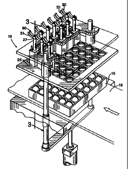
Referring now to the drawings, Figure 1 illustrates one embodiment of an
automated multi-site injection apparatus 10 according to the present
invention. As
shown, the apparatus 10 includes a flat 15, a stationary base 16, and a
plurality of
injection delivery devices 25 with fluid delivery means such as lumens or
needles) 90
positioned therein. The flat 15 holds a plurality of eggs 20 in a
substantially upright
and aligned position. The flat 15 is configured to provide external access to
predetermined areas of the eggs 20. The egg is held in by the flat 15 so that
a
respective one egg is in proper alignment relative to a corresponding one of
the
injection devices 25 as the injection device 25 advances towards the base 16
of the
apparatus. As used herein, a "lumen" is a cavity or inner open space of a tube
which
can be provided by a syringe or needle. A lumen for delivery of a treatment
substance
may be within a needle, or between a needle and an outer guide or sleeve.
Multiple
lumens may be formed within a single needle, with the outlet ports positioned
on
different locations on the needle.
Each of the plurality of injection devices 25 have opposing first and second
ends 26, 27. The devices 25 have a first extended position and a second
retracted
position. As shown in Figure 4, upon extension of the injection device 25, the
first
end 26 is configured to contact and rest against predetermined areas of the
external
egg shell. As shown in Figure 1, when not injecting, the injection devices 25
are
retracted to rest a predetermined distance above the eggs and stationary base
16.
Alternatively, the base 16 can be longitudinally slidably moveable to position
the eggs
in proper position relative to the injection delivery device 25 (not shown).
For ease of
discussion, the description describes a unit with a single multi-site
injection device 25
(shown as a top injection device) but the description also applies to an
apparatus with
multiple injection devices 25', 25" (exemplarly shown in Figures 10 and 11),
or,
alternatively, one or more of single bottom or side devices. For ease of
illustration,
Figure 3 shows a single needle device, essentially
_g_
CA 02330855 2001-03-21
the same as the device currently marketed by Embrex Inc., but with the fluid
supply
altered so that a second treatment substance rather than a disinfectant
solution is
channeled through the lumen between the needle and the outer guide. However, a
dual needle device, such as is shown in Figure 7, is currently preferred so
that the
outer lumen remains available for a cleansing solution.
In an alternate embodiment of Figure 3, a single needle device may be
employed, and suitable valves and controls used (not illustrated) so that a
treatment
solution passes through the outer lumen and is administered into the egg while
the
device is inserted into the egg, and a cleansing solution passes through the
outer
lumen and cleanses the needle while the device is withdrawn from the egg, and
prior
to insertion into the next egg for delivery.
Preferably, as shown in Figure 3, the second end 27 of the injection delivery
device includes first and second inlet ports 28a, 28b which are configured to
receive
first and second tubing 30, 31 respectively. The first and second tubing are
in fluid
communication with first and second treatment substance chambers 110, 120
(Figure 13). In order to maintain the separate delivery paths 60, 61 of the
treatment
substances through the injection device 25, the injection devices 25
preferably
include a first and second passage (not shown) formed therein, which are in
fluid
communication with the first and second inlet ports 28A, 28B, respectively, as
would
be understood by one skilled in the art. In one embodiment of the present
invention,
as shown in Figures 3 and 4, the delivery paths 60, 61 are maintained separate
from
the other even when the lumens or needles) are injected into the egg.
Alternatively,
the delivery paths 60, 61 can merge immediately or a short time prior to
delivery into
the egg.
As shown in Figure 3, A multi-site in ovo injection head 25 for delivering
compounds inside an egg comprises a body member 40 having opposing top 43 and
bottom 41 end portions and an elongate longitudinal aperture formed therein;
and a
delivery device positioned in said aperture. The delivery device has at least
two
lumens formed therein (in the case where the lumen between the guide and the
inner
needle is used to carry compound to be introduced into the egg, the guide
itself being
considered a portion of the delivery device). In a preferred embodiment as
illustrated
in Figure 7, the drug delivery device comprises a first needle and a second
needle,
each of the needles containing one of said lumens. Also preferably, the first
and
second needles are configured to deliver substances through the lumens thereof
to
spatially separate locations within an egg to be
-9-
CA 02330855 2006-O1-31
injected. The device includes an egg locating member, or egg engaging member
26,
connected to the body member bottom end portion, which as illustrated is
slidably
connected to the body member and includes a spring 42 to both cushion the
engagement, and hold the egg in place during the downstroke of the injection
head.
As illustrated, an outer guide 80 is provided to pierce the egg shell, and the
needle 60
then extends beyond the outer guide and into the desired compartments of the
egg (see
Figure 4). The device illustrated in Figure 3 is commercially available from
Embrex
Inc. in a single needle embodiment (where a chlorine cleansing solution only
passes
through the outer lumen), but not as a dual needle embodiment as illustrated
in Figure
7.
The dual needle embodiment of Figure 7 is currently preferred because the
outer lumen 61 (see Figures 5 and 6) then remains available for a sanitizing
or
disinfecting solution. Where a dual needle embodiment is used, the inlet head
43 is
modified to incorporate additional ports for introduction of additional
compounds.
As shown by the block diagram in Figure 13, the apparatus 10 preferably
includes a main controller 100, first and second treatment substance chambers
110,
120, associated valves 111, 121 and one or more drive means such as pumps 112,
122
operably associated with the substance chambers for delivering the appropriate
amounts of treatment substances to the injection delivery device 25. Although
the
apparatus 10 is illustrated as having a separate drive means for each fluid or
treatment
chamber 110, 120, it will be appreciated by one of skill in the art that the
invention is
not limited thereto. Indeed, a single electric or pneumatic pump can be
connected to
each substance chamber to deliver each treatment substance to the inlet ports
30, 31 in
the injection device. Preferably, the apparatus 10 incorporates one or more
high speed
peristaltic pumps or solenoid activated pumps, actuated to deliver precise
dosages of
treatment substances to the injection devices and ultimately to the egg. One
such
peristaltic pump is described in U.S. Patent No. 5,941,696 of Fenstennacher
and Hall,
issued August 24, 1999.
Optionally, as illustrated by the dotted line paths in Figure 13, the
apparatus
10 can be configured to separately store the treatment substances in the
respective
chambers 110,120 and then channel them through a single lumen for delivery
into the
egg. A valve, controlled by the controller, is required to
-10-
CA 02330855 2000-10-30
WO 99/34667 PCT/US99/00572
alternately switch from one treatment fluid source to the other. Switching is
timed
with positioning of the needle so that different fluids are injected in
different --
compartments within the egg. The different treatment substances can each be
provided in liquid, solid, gas or aerosol form, or any other suitable form, so
long as
S the substances are substantially separated from one another (e.g., liquid
treatment
substances separated by an ini:ervening gas bubble) so that different
treatment
substances are placed in different compartments.
Also preferably, as also shown in Figure 13, the apparatus 10 includes a
cleaning solution chamber 140 operably associated with the controller 100 and
l0 plumbed to be in fluid communication with each of the separate substance
delivery
channels 115, 125 upstream of the injection delivery device 25 as well as the
one
or more fluid or substance delivery paths 118, 128 (130) in the injection
device
itself 25. This will allow the delivery paths 118, 128 (130) to be flushed
with a
decontamination fluid to maintain a preferred level of sterility in the
apparatus so
:l5 as to reduce the likelihood of cross-contamination between eggs or the
growth of
undesired contaminants in the delivery paths to help maintain the apparatus in
optimum performance condition. Any conventional cleansing solution may be
used, with chlorine cleansing solutions preferred.
In operation, in one embodiment of the present invention, a controller 100
:'.0 directs the opening of the valves 111, 121 to release predetermined
dosages of
treatment substance into first and second tubes 30, 31. The associated drive
means
or pumps 112, 122 forces the substances into delivery paths 115, 125 (such as
through tubing 30, 31) in fluid c;ammunication with each of the injection
delivery
devices 25 via inlet ports thereon 28a, 28b.
S In order to inject the shell with the desired treatment substances, as
illustrated by Figures 3 and 4, the apparatus 10 preferably includes a shell
piercing
means such as an outer guide punch 80 which punctures at least one small
opening
into the outer shell of an egg. Alternatively, a high pressure water jet can
also be
employed. The outer guide punch 80 is preferably formed from a durable and
rigid
?.0 material, or the needle or injection device itself can serve as the shell
piercing
means. Advantageously, configuring the outer guide punch 80 to pierce the
shell
of the egg will help preserve the life of the needles) 90 as the needles) 90
can be
inserted into the opening formed by the punch 80 and will not have to pierce
t:he
-11-
CA 02330855 2000-10-30
WO 99/34667 PCT/US99/00572
shell before entry into the egg.
Also, as shown in Figure 4, the outer guide punch 80 preferably does not w -
advance into the inner shell membrane. The needles) can be formed of any
suitable material such as but not limited to stainless steel or plastic. If
formed of
plastic, a compatible epoxy can be employed to assemble in position in the hub
assembly 40. The egg inserting ends of the needles) 90 are preferably
sufficiently
sharp to be able to pierce th,e inner shell membrane or chorioallantois with
minimum tearing attributed thereto. Alternatively, blunt, dull, or side-port
needles
can be employed, particularly vvhere it is desired that the needle avoid
piercing a
particular underlying membrane or the embryo proper.
In operation, the outer guide 80 preferably advances a predetermined short
distance into the egg. The inj ection device 25 then extends the lumens or
needles)
90 into the egg through the prei:ormed opening. The needles 90 are configured
to
release (preferably simultaneously) a predetermined dosage of the substances
into
l5 predetermined sites, such as above or below the air cell and into the
amnion of the
avian embryo (as will be discussed in more detail hereinbelow). The needles)
90
are then retracted into the outer guide punch 80 and the guide punch 80 is
returned
to the stationary storage position within the bottom portion of the injection
device
26 and, as described above, the c,ntire injection unit is then retracted and
preferably
flushed before the next flat of eggs are advanced. Preferably, the exterior
surface
of the needles and/or lumens are then flushed to disinfect or clean the
injection
device 25 such that remnants of the injected egg or other contaminants are
flushed
out of the delivery paths 60, 61l and the exterior portion of the needle tips)
are
sanitized. In a preferred embodiment, as illustrated in Figure 8, the outer
guide
~!5 punch 80 includes a plurality of apertures 81 formed therearound to allow
the
cleaning solution to flush the exterior surface as well as the interior
lumens.
Turning back to Figure 4, the injection delivery device 25 is shown in a
preferred position in the egg, i.e., one lumen 61 delivering a first substance
in the
air cell and the other lumen 60 extending farther down to deliver a second
3~0 substance below the chorioallantois membrane. As shown in Figure 5, the
outer
guide punch 80 defines the second delivery path 61 (one lumen) and a needle 90
held with the inner diameter of the guide punch 80 defines the first delivery
path 60
(a second lumen). The needle 90 may include a curved end 92 to direct the
-12-
CA 02330855 2000-10-30
WO 99/34667 PCT/US99/00572
substance in a predeterminef. direction when released into the egg. This
configuration can provide further separation of treatment materials when
released -
within the egg. Figure 6 illustrates the separate delivery paths (exemplarly
shown
as concentric lumens) of the materials within the injection head 75.
S Figures 7 to I2 illustrate alternative configurations of an injection head
75
that provide alternative substance. delivery paths into the egg. In a
particularly
preferred embodiment, Figure 7 shows two separately extending needles 190a,
190b, one extendable a predetermined further length than the other. The outer
guide punch 80 can provide a aeparate lumen or delivery path, but is
preferably
used to provide an outlet for a sanitizing fluid or cleansing fluid. For a
third
treatment substance, as noted above, Figure 8 illustrates three needles, a
central
needle 290b and two side needles 290a, 290c. As illustrated, the central
needle
290b extends a further distance vthan the side needles 290a, 290c. The side
needles
290a, 290c may be curved to direct the treatment substances away from the
central
l S needle 290b and the other opposing side needle. Alternatively, one or more
of the
needles can be a side port needle which can direct the substance in an angular
trajectory path relative to the longitudinal extension of the needle.
Figure 9 illustrates two needles 490a, 490b structurally joined a major
distance of the length of the needles. Alternatively, a single needle or
device with
;'0 multiple lumens could be used. Figure 10 shows a top and bottom mufti-site
injection delivery device 75, i'5' each having alternatively configured
needles
590a, 590b, 590c, 590d for directing the substance in a desired area of the
developing egg. Similarly, Figure 11 illustrates a side and top mufti-site
injection
delivery device 75, 75". Note that where two (or more) holes are made in the
egg
25 shell, particularly in a configuration that would cause the contents of the
shell to
drain from the egg, then at least one of the holes (preferably the lower hole)
should
be sealed, in accordance with known techniques, to prevent draining of the
egg.
Alternatively, an injection delivery device may have a needle with two
lumens that terminate into a single lumen at a position prior to the end of
the
30 needle. This configuration keeps the substances separate a major portion of
the
substance delivery path but allows them to mix at the site of injection.
The apparatus of the instant invention can also employ a side or bottom
injection device 25', 25". One or more of these alternative injection devices
can be
-13-
CA 02330855 2001-03-21
used concurrently with a top injecting device or subsequent or prior in time.
Of course
the flat must be altered to provide access to the appropriate part of the egg
shell.
When injecting from the bottom, it is preferred to position the bottom
injection device
opposing the top injection device and further preferred to configure the
injection head
75 and depth of injection to inject into the yolk sac. Note that when
injecting into the
yolk sac a small needle such as a 25 gauge needle is preferred in order to
reduce the
risk of yolk sac leaks. When injecting from the side it is preferred that the
needles be
inserted at an angle below 90E with respect to a plane normal to the
longitudinal axis
of the egg. As shown in Figure 11, it is more preferred that the side
injection head
75" be positioned and configured to enter the egg at about 45 degrees or less
relative to the longitudinal axis of the egg.
Figure 12 illustrates an interchangeable needle hub 33 having a plurality of
needles 890a, 890b, 890c. The needle hub 33 is provided with an alignment tab
33a
that is configured to matingly engage a complimentary-shaped detent 46b in the
illustrated injection head 46. Accordingly, the needle hub 33 can be alignably
assembled to the injection head 46.
In two preferred embodiments as illustrated in Figures 7 and 8, the injection
head 75 includes a 16 gauge outer guide punch 80 which surrounds two or three
25
gauge needles therein.
Treatment substances may administered as a bolus in the same or different
physical form, such as liquid, gas, solid (e.g., a powder or a unitary
erodable time-
release matrix), aerosol or spray, etc.
The bolus of treatment substance may be administered into any suitable
compartment of the egg, including intraperitioneally, intramuscularly, or
subcutaneously within the embryo, into the yolk sac or stalk, into the liver
or lungs of
the embryo, into the air cell, the allantoic sac, or the amniotic fluid, etc.
In some
cases it may be desireable to administer two different substances into
different
locations within the same compartment (e.g., intraperitoneally or
intramuscularly, or
even into the, amniotic fluid for rapidly absorbed but otherwise incompatible
treatment substances). In addition, it may be desireable in some cases for the
first
and second treatment substances to be the same, but simply administered in
different locations within the egg.
Treatment substances that may be administered include, but are not limited
to, vaccines, hormones, growth-promoting agents, etc.
In one preferred embodiment, one of the treatment substances is Newcastle's
disease vaccine, and the other treatment substance is Marek' s disease
vaccine.
Marek's disease vaccine is preferably administered into the region defined by
the
amnion; Newcastle's disease vaccine is preferably administered into
-14-
CA 02330855 2000 10 30 ::::.~;:::;:::::::::::
......... . . .. .. .. :. ............
::.. :;:.::~..;:..../:':., . ...: : .::: -~:~;:... ~ . . :. . ..~:::
.::. :. . ~.: : ..n:. .~ ~.. :: ~:::: ~....~.~.~..t-..~'.-
....~....:::::::::::. :::::-:: ::::::.::....:.::....::...:...:..
:;: ::.::~:;.:~x~~.: ~::::';::-.:::c::::::: ::.::.: ::::: ::.::. ::.::::
~ ~ ~ ~ ~ ~ 1 ~ 1
f
~ ~ ~ 1 1 ~ ~ ~ ~ ~
~ ~ ~ ~ 11 ~ ~ ~ ~~~ ~~~
~ ~ ~ ~ ~ ~ ~ 1
~ ~ ~ ~ ~ ~ ~ ~ ~ ~ ~ 1
the air cell.
In another preferc~ed embodiment, one of the treatment substances is a
biologically active substance such as a vaccine, antibiotic, hormone,
probiological
culture (e.g., a competitive exclusion media), and the other is a marker such
as a
dye. The marker can serve as a positive control to confirm injection, for
example
in the case of eggs subsequently found to be nonviable.
Although a few exemplary embodiments of this invention have been
described, those skilled vn the art will readily appreciate that many
modifications
are possible in the exemplary embodiments without materially departing from
the
novel teachings and advantages of this invention. Accordingly, all such
modifications are intendE:d to be included within the scope of this invention
as
defined in the claims. The; invention is defined by the following claims.
A~'UEaDED SHEET
:::::::::::::::.::::::;::::::::.::~::~::::::. P ~ S :, :::
:::. >:~,-.:::..: : :-: ;::: ; :_ .: :-, _ ~ :. _ . v: ::: :~:::
::w .:...:. ~ SUBSTITDTE A
::~t'lit'~~t~.;'~._:~:'~_:.~~,~~.::::::::=