Note: Descriptions are shown in the official language in which they were submitted.
CA 02331046 2001-O1-15
-1-
METHOD AND SYSTEM FOR INTERNET CONNECTION AND
COMMUNICATION MANAGEMENT
FIELD OF THE INVENTION
The present invention relates to telecommunications. In particular, the
present
invention relates to a method and system for managing connections and
communications over
the Internet.
BACKGROUND OF THE INVENTION
The heart of the World Wide Web (~'~ is the transmission of Hypertext Mark-up
Language (HTML) pages through the use of the Hypertext Transfer Protocol
(HTTP). The
specific file to be transmitted is ;;enerally described using a Uniform
Resource Locator
(URL). In its infancy the URL was used to specify nothing more than HTML
files, leaving
the web as a collection of static pages. As the HTML standards evolved tables
were added to
allow for the formatting of pages, and forms were added to allow some form of
interactivity.
To create dynamic pages, tailored to a particular client, scripting languages
were
added. Languages like Perl, PHP (PHP Hypertext PreProcessor), and Active
Server Pages
came into popular use for their ability to assist in the development of
dynamic pages. These
languages rely upon server-side processing for their abilities, which
insulates the client
machine from having to process am~thing other than the raw HTML. Though this
technology
is popular, the languages are somevvhat platform reliant, causing a server to
be locked in due
to the extensive development done an the scripts.
JavaTM, a product of Sun MicrosystemsTM, and JavaScriptTM, designed by
Netscape
Communications Inc.TM, now a part of America OnlineTM, allow servers to
include client-side
processing, typically through the use of applets, in the documents they share.
This alleviates
some of the processing burden on a high traffic HTTP server, and allows a
greater amount of
user interaction. These technologies; make it possible to create pop-up
windows and dialogue
boxes that allow the user to dynamically interact with the server, or with
another client that
is also connected to the server. However, the ability to offer interactivity
is limited by the
static nature of a conventional web browser. Typically after a page has been
loaded it is not
possible to modify it, unless a refresh of the content is forced at fixed
intervals. As a result of
CA 02331046 2001-O1-15
-2-
this drawback interactivity must be offered immediately upon loading the page,
or it can be
offered when a user clicks a link on a page. It would be of greater value to
be able to
implement user interactivity whenever needed or desired by a content or
service provider,
instead of either relying upon the user to request interaction, or offering it
by default with
every page.
With the emergence of electronic commerce, online merchants now desire the
ability
to monitor the traffic through their sites and to interact with clients in the
same fashion that
a bricks-and-mortar retailer does. Instead of mere statistics, it would be
highly advantageous
for electronic merchants to be able to easily monitor a client session and
monitor the client's
to progress through their site to build a true client profile. It would also
be advantageous for the
merchant to have the ability to create: interactions between the client and a
sales representative
and to permit the sales representative to show the client items in which he or
she may be
interested. The ability to track a customer as a return customer is also
desirable.
As is known to those of skill in the art, it is possible to implement the
tracking systems
using a combination of cookies (small text files stored by the client web
browser) and server
side processing languages. Interactivity can be implemented through the use of
JavaTM applets
and JavaScriptTM embedded in the HTML generated by the server side scripts.
Such
functionality is typically difficult to implement, and requires the creation
of custom client-side
applets and scripts, as well as a redesign of the server side functionality to
allow the server-
2o side scripts to interact with the new client-side functionality.
As a result of the initial diffiiculty to design such tools and the cost
associated with
them, it is common for most commercial web sites to bypass the development of
tracking
functionality in the first iteration of a. site. Attempting to add such
functionality at a later date
typically requires a redesign of all the functionality, wasting the effort
spent on the first
release of the site. This is not productive from either a time or a cost
perspective.
Another issue that impedes the development of interactivity with a client in
commercial web sites is the heavy reliance upon server side scripting. This
can add a
computational load to the server that can strain the server's resources in
times of heavy use.
This can also limit the scalability of the system. Further, in order to track
a user properly, it
3o is crucial that the server has access to a record of the last transaction
with the client. Simply
adding an additional server, with an identical set of scripts is insufficient.
Generally a back
CA 02331046 2001-O1-15
-3-
end processing system must be implemented that can reliably store the
preferences and
transactional history of the users, .and allow access to this data from
multiple machines.
It is therefore desirable to provide a method of delivering user interactivity
features
to an existing web site without requiring a substantial redesign. It is
further desirable to
provide a method of delivering client tracking and monitoring features without
implementing
platform dependent scripting languages. It is desirable, further still, to
provide these methods
in a manner that allows scalability and minimises the loading of the server
side processor.
SUMMARY OF THE INVENTION
It is an object of the present invention to obviate or mitigate at least one
disadvantage
of previous Internet connection and communication management methods and
systems. In
particular, it is an object of the present invention to provide a method and
system for tracking
client interactions on e-commerce web sites, and to provide enhanced
communications with
such clients.
In a first aspect, the present invention provides a method for managing
communications between a client ,md a content provider communicating over a
distributed
network environment, such as the Internet. The method commences with receipt
of a service
response from the content provider. The service response is then modified to
provide added
functionality, such as tracking information or the opening of a communication
channel with
third party such as a customer service representative, and this modified
response is transmitted
to the client. The method can also include load balancing between a plurality
of servers of the
content provider.
Generally, the service response is in reply to a previous service request from
the client.
If so, the service request is logged, usually by means of caching an HTTP
header of the
service request, prior to being transmitted or routed to the content provider.
Service requests
are detected by monitoring the distributed network environment to intercept
content addressed
to the content provider. The content of the service request can be used to
determine the routing
of the service request.
The content of the service response and the service request can be modified in
a
number of ways. An applet can be inserted into the response to provide certain
functions, such
as bi-directional communications (instant messaging or voice communications),
access to a
CA 02331046 2001-O1-15
-4-
stored client profile, or access to a client history. The service response or
request can also be
parsed to identify insertion tags or additional content, in a suitable markup
language, can be
pushed to the client.
In a further aspect of the present invention, there is provided a method for
providing
content enhancement services to a content provider through a reverse proxy
server. The
method consists of receiving a service request from a client, transmitting the
service request
to the content provider, receivinf; a reply from the content provider, the
reply including
content, enhancing the content; and transmitting the enhanced content to the
client. The step
of enhancing the content can include any of the methods described above in
relation to
to modifying the content.
In another aspect, the present invention provides a method for providing
client profile
information to a content provider through a reverse proxy server. The method
consists of
receiving a service request from a client, logging information in response to
the service
request in a client profile and, transmitting the client profile to the
content provider.
In a still further aspect of the present invention, there is provided a method
for
providing content enhancement services to a content provider through a reverse
proxy server
in conjunction with an application ;>erver. The application server provides
application services
which are requested directly or indirectly by the application broker by way of
messages.
There is also provided a system for managing communications between a client
and
2o a content provider over a distributed network environment. The system
permits
implementation of the method of the present invention, and comprises a content
provider
ingress port, a late binding engine, and a client egress port. The content
provider ingress port
receives service responses from a content provider. The Iate binding engine is
connected to
the content provider ingress port, and modifies the service responses. And,
the client egress
port transmits the modified response. According to an embodiment, the system
further
includes a client ingress port for receiving a service request from a client,
a tracking engine
for logging the service request, and a content provider egress port for
transmitting the service
request to the content provider.
According to a further embodiment, the system further includes an application
server
3c~ for providing application services 1:o the system.
CA 02331046 2001-O1-15
-5-
BRIEF DESCRIPTION OF THE DRAWINGS
Preferred embodiments of the present invention will now be described, by way
of
example only, with reference to the attached Figures, wherein:
Figure 1 shows a general nfawork configuration for a connection and
communications
management system according to the present invention;
Figure 2 is a block diagram of an application broker according to the system
of Fig.
l;
Figure 3 is a flow chart of a method for managing connections and
communications
in a distributed environment according to the present invention;
to Figure 4 is a continuation of the flow chart of Figure 3;
Figure 5 is a continuation of the flow chart of Figures 3 and 4;
Figure 6 is a continuation of the flow chart of Figures 3, 4 and 5;
Figure 7 is a flow chart of a client identification step according to the
present
invention;
Figure 8 is a flow chart o f a content based routing step according to the
present
invention;
Figure 9 is a flow chart of a load balancing step according to the present
invention;
Figure 10 is a flow chart of a late binding step according to the present
invention;
Figure 11 is block diagram of a further embodiment of an application broker
according
to the present invention;
Figure 12 shows a general network configuration for a connection and
communications management system employing the application broker of Figure
12;
Figure 13 shows an example of a network configuration according to the present
invention;
Figure 14 shows a general network configuration for a connection and
communications system management system according to another embodiment of the
present
invention;
Figure 15 is a block diagram of the application server of Figure 14;
Figure 16 is a chart illustrating the flow of data relating to a logging
operation;
3o Figure 17 is a chart illustrating the flow of data in a late binding
operation;
Figure 18 is a chart illustrating the flow of data in content based routing;
CA 02331046 2001-O1-15
-6-
Figure 19 is a chart illustrating the flow of data in load balancing;
Figure 20 is a block diagram illustrating the interaction service of the
present
mvenhon;
Figure 21 is a block diagrun illustrating the instant message proxy service of
the
present invention;
Figure 22 shows states of entries in a storage technology of the present
invention;
Figure 23 is a block diagram illustrating system scaling through the use of a
load
balancer and multiple application brokers; and
Figure 24 is a diagram illustrating system scaling by the scaling of CORBA
components.
DETAILED DESCRIPTION OF' 'THE INVENTION
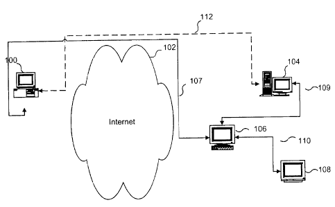
Referring to Figure 1, according to an embodiment of the present invention, an
Internet
connection and communication management system includes a client 100, a
content provider
104, an application broker 106 and an interaction device 108.
In operation, the client 100 sends a service request to the content provider
104, through
the use of a packet based network such as the Internet 102, or other
distributed network
environment. By service request or content provider service request, we mean a
request made
the content provider including, for example, an HTTP request for content from
the content
2o provider. By contrast, we use the term application service request to refer
to a request for an
application service including, for example, an HTTP request made to the system
by the client
for a service such as paging a we;b attendant or an XML message from the
application
broker(reverse proxy server) to they application server. Similarly, by service
response or
content provider service response vre mean a response to the service request
including, for
example, an HTTP response from the content provider while application service
response
refers to a response to the application service request.
The content provider 104 generally consists of at least one target server. The
service
request to the content provider 1(14 is routed through the application broker
106. The
application broker 106 forms a virtual connection 107 with the client 100, and
connects the
CA 02331046 2001-O1-15
_7_
client 100 to the desired content provider 104 by extending the virtual
circuit, as indicated by
arrow 109. This occurs without client intervention and is thus transparent to
the client 100.
The client 100 perceives a direct connection to the content provider 104 along
a path 112
through the Internet 102 directly to the content provider 104, when in reality
the data is being
S routed along paths 107 and 109 through the application broker 106. Any
service response to
the client's requests are again routed through the application broker 106,
permitting the
application broker 106 to modify the responses, by injecting data into the
stream or otherwise.
This permits added functionality to be provided to both the client 100 and the
content provider
104, such as direct interaction with the interaction device 108.
to The application broker 106. is a form of a reverse proxy server. As is
known to those
of skill in the art, a proxy server is a device inserted between a client, and
all its Internet
connections. The requests of a given client 100, and all other clients on a
network, are routed
to the proxy server, which in turn forwards the requests to an external
server. The external
server perceives the connection as originating from the proxy server and
returns the
1:~ information to the proxy server, which then forwards the data stream to
the requesting client.
This allows a centralised connection to the Internet for a single network, and
reduces the
number of points at which entry ca.n be obtained. It also allows the
monitoring of data flow,
and the caching of requests, so that if two clients make similar requests in a
short period of
time the data can be provided out o f the cache instead of using bandwidth to
make the request
2o a second time.
Acting as a reverse proxy server the application broker 106 ensures that all
connections to the Internet 102 by the content provider 104 are facilitated
through the
application broker 106. By serving ;as a reverse proxy the application broker
106 is able to add
content to a bi-directional data stream between the client 100 and the content
provider 104.
2~ The application broker 106 when fiznctioning as a reverse proxy server also
provides routing
capabilities for transport layer protocols, such as HTTP.
To monitor and intercept content addressed to the content provider 104, the
application
broker 106 inserts itself between the client 100 and the content provider 104
so that all
transactions with the client 100 are routed through it. To insert itself
between the client 100
3o and the content provider 104, the application broker 106 can use a variety
of techniques
known in the art. These techniques include, but are not limited to the
designation of the
CA 02331046 2001-O1-15
_g_
application broker 106 as a foreign agent in accordance HTTP (with XML
embedded), or
situating the content provider 104 logically behind the application broker
106, so that the only
connection that the content provider 104 has to the network is through the
application broker
104. In these ways all the traffic. for the content provider 104 is directed
through the
application broker 106, and the connection to the application broker 106 is
transparent to the
client 100.
As will be understood by those of skill in the art, conventional general
purpose
computer systems can provide the functionality of the application broker 106,
client 100, and
content provider 104. The conventional computer systems generally include
standard
1o hardware components, as are well known to those of skill in the art,
including a computer
processor unit, RAM and ROM memory, a display, a keyboard, other input
devices, such as
a mouse or trackpad, a modem or other device for connecting to Internet 102,
and a mass
storage device. The system software required for the operation of such a
conventional
computer system is stored in memory, and/or on the mass storage device. The
software system
1:~ generally includes a kernel or operating system (OS) and a user interface
(UI). The OS and
UI can, for example, be provided by Microsoft Windows 2000TM, Microsoft
Windows NTTM,
LinuxTM, SolarisT"" or other similar operating systems. One or more
application programs, such
as application broker software, can be loaded for execution. In a presently
preferred
embodiment the application broker software is a Microsoft Windows NTTM, or
Microsoft
2o Windows 2000TM service, or a LinuxTM or Solaris''M daemon. The software
system further
includes a UI, preferably a graphical user interface for receiving and
displaying monitoring
statistics and status messages.
The content provider 104 and application broker 106 are generally composed of
networked computers, or a cluster of computers, operating server software to
allow the sharing
24~ of files with other computers on the network. The software system for such
networked
computers further includes a netvvork-aware OS and a file sharing server
designed to fill
requests for network file sharing. The client 100 can be any conventional
computer or
workstation, with network access. The operating system is network-aware and a
client
application program such as Netscape NavigatorTM, Microsoft Internet
ExplorerTM, or
3c~ OperaTM is installed to provide the; ability to browse the Internet 102.
CA 02331046 2001-O1-15
-9-
Interaction device 108 is a device for operation by an operator or customer
service
representative to provide direct communication with client 100 and to provide
guided
interaction between client 100 and content provider 104. For example in a
presently preferred
embodiment, interaction device 108 consists of a general purpose computer as
described
above and a communication console, such as a headset/microphone or other
communications
device. Interaction device 108 also includes application software that enables
it to
communicate with application broker 106.
The application broker 106 is logically comprised of several distinct units as
shown
in Figure 2. The first unit to be encountered by a message upon entering the
application broker
106 is the client ingress 114 wher~° messages from clients are
received. Upon receiving a
connection from a client, including a service request, at the client ingress
114, the messages
are passed, or streamed to the client identifier module 116 which handles the
identification
of the client and other state management and logging issues. Logging the
service request
occurs at this point, so that the application broker 106 can track the
responses received back
from the content provider 104. The client identifier module 116 optionally
modifies the
messages so that the interactions with one client can be maintained as
separate from the
interactions with another. This modified data stream is then sent to router
120 which connects
the client 100 to the content provider 104 by extending the virtual circuit to
contain the
content provider 104. The muter 121) is used so that optimal paths to the
content provider 104
can be achieved. The routing can be rule based or rely upon the content of the
messages
received from the client 100, which will henceforth be referred to as content
based routing.
Part of the routing rules are those associated with the load balancer 122,
which is designed to
allow the distribution of connections and loads to a number of content
providers 104 operating
in unison. Thus the application broker 106 is able to support scalability on
the content
provider side.
The client identifier 116 and the muter 120 serve as components of the
tracking engine
180, which logs service requests and builds the client profile. After the
destination server has
been chosen by the muter 120 and the load balancer 122, the address of the
content provider
104 is inserted into the message, and the message is passed to the content
verifier 124, while
3o the routing information is stored for use when a reply from the content
provider 104 is
received. The content verifier 124 e~:amines the payload of the message and
tests the message
CA 02331046 2001-O1-15
- 10-
for data integrity. The content verifier 124 drops messages that are corrupt
and these must be
resent. Upon being verified, messages are sent to the server egress port 126
and from there are
sent to the content provider 104. Upon receiving message from the content
provider 104, a
message enters the server ingress port 128, and is immediately sent to the
content verifier 124,
so that corrupt messages are not processed and sent to the client 100. If a
message is corrupt
it is dropped. Valid messages are sent to the late binding engine 130. Here
routing information
saved by the muter 120 is used to determine the destination of the message. As
well additional
content is prepared and inserted into the messages. The interaction device
interface 132 allows
the interaction device 108 to interact with the late binding engine 130, so
that an operator at
1o an interaction device 108 can instruct the late binding engine 130 to
insert applets into the data
stream, or can issue requests on behalf of the client 100. After the late
binding engine 130 has
optionally inserted information, the packets are sent to the client egress
port 134 and from
there are transmitted to the client 1l)0.
The operation of the application broker 106 as a content enhancing reverse
proxy is
shown in Figures 3, 4, 5, and 6. The application broker 106 has a listener
thread that monitors
the client ingress port 114 for an :incoming connection. The listener thread
monitors the
distributed network environment, Internet 102, for content addressed to the
content provider
and allows the interception and/or redirection of content addressed to the
content provider.
If the listener thread does not detect an inbound connection, the process
repeats 202. If a
2o connection is detected, the connection is passed to the identification of
the client in step 204.
The listener thread polls the incoming connection and provides a method of
receiving
a request from the client 185. A client identification process 204 ensues and
the identified
client 100 proceeds to step 208 where the application broker 106 accepts the
connection and
creates a virtual circuit between the client 100 and the application broker
106. After creating
a virtual circuit, a handler thread is spawned in step 212 to perform
connection management
after which step 214 performs content based routing.
The steps 204 through 214 serve to log the service request as step 190. The
logging
of the service request, step 190, is used to build a user profile of the
client 100, and is also
used when the response arrives from the content provider 104 to decide where
to send the
3o content. The destination address, provided by the content based routing of
step 214, is
checked for validity in step 216. If t'.he destination address is invalid a
DNS error message is
CA 02331046 2001-O1-15
-11-
generated in step 218. If the destination address is valid load balancing is
performed in step
220.
After determining to which server the request is to be sent, the destination
server is
checked to see if it is active in step 222. If the content provider is not
active at this point, a
gateway timeout error is generated in step 224. If the server can be reached
the virtual circuit,
established in step 208, is extended to include the content provider 104 in
step 226. At this
point the connection between client 100 and content provider in step 104 has
been negotiated
and the application broker 106 processes an inbound service request from the
client 100 as
step 230.
1U The request is now tested for corruption in step 234 by the content
verifier 124. If the
request is corrupt an invalid message error is generated in step 238. If the
request is not
corrupt, an outbound server request is transmitted to the server in step 236.
The content
provider 104 analyses the request and acts upon it, and will then reply to the
application
broker 106, which receives the inbound service response from the content
provider 104 in step
240. The application broker 106 will then check the inbaund response for data
corruption in
step 242, and if the response is corrupt the application broker 106 generates
an invalid
message error in step 238. If the data is not corrupt the late binding engine
130, is allowed to
add content in step 248, and the outbound service response is transmitted to
the client 100 in
step 250. The application broker 1(i6 then checks to see ifthe session is
complete in step 252,
2o and if it is, the virtual circuit is torn down and the application broker
106 terminates the thread
in step 254. If the session is not complete the application broker 106 goes
back to step 230,
where it receives an inbound service request from the client.
As will be clear to those of skill in the art, the above-described method can
be
implemented in various ways. For exemplary purposes, a description of a
presently preferred
2_°°, implementation will now be detailed. Figure 7 depicts a
method of state management to allow
the identification of a client, as would be performed in step 204. The
incoming client request
is examined in step 256. The client request is examined to determine if a
cookie is present
from a previous session in step 2!58. If no cookie is present a new ID tag is
placed in the
HTTP response to the client 100 in step 260. A new session ID is then created
in step 264 and
3( attached to the HTTP response as well. If a cookie is present, the cookie
is examined to see
if it is from an existing session in step 262. If the cookie is not from an
existing session a new
CA 02331046 2001-O1-15
- 12-
session ID is created in step 264. If the session is current the existing
session ID is used as
shown in step 266. After the retrieval or creation of client and session ID
numbers they are
stored in the message in step 268, and the state management process
terminates.
The content based routing of step 214 is shown in Figure 8. At step 280, the
message
header is cached for use later as an identifier. The content is then examined
for the presence
of content directives in step 282. I:F there are no content directives the
request is routed to the
default target in step 284, and the routing type is recorded for further use
in step 290. If there
is at least one content directive, th.e highest priority directive is acted
upon in step 286, and
the content directives are removed in step 288. The routing type is then
recorded for further
1(~ use in step 290.
Figure 9 illustrates the load balancing of step 220. The load balancer 122
examines the
request for load balancing eligibility in step 292, and if the request is
eligible a suitable
destination content provider 104 is selected according to predetermined
criteria at step 294.
The destination content provider's address is placed into the request in step
296 and the
14~ process terminates.
Refernng to Figure 10, the late binding of step 248 examines HTTP server
responses
for HTTP objects containing HTML documents. If it does not detect one then no
late binding
is performed. If it does detect one then the header is modified 300, and it is
checked for an
insertion token 302. If there is no insertion token then the end of a data
stream is padded so
2U that the packet length matches the length described in the header 306,
whereas if there is a
token an object is inserted at the te~ken's location 306. The response is then
checked to see if
there are special instructions based on routing information or client ID 308.
If there are
instructions they are performed 310 and then the late binding step is
complete.
The examination of the data flow from the content provider can optionally
include a
24~ search for Extensible Mark-up Language (XML) tags, as keys for the
insertion of specific
content or applets. In the absence of these tags, the application broker 106
allows the insertion
of JavaTM applets into the client-bound data stream at the initiation of an
operator. The
insertion of the JavaTM applets can occur at either the loading of a new page,
or it can be
initiated by the application broker 106 while using conventional server push
techniques.
3U The server push techniques can also be used after the interactive JavaTM
applets are
loaded to allow an operator at an interaction device 108 to interact with the
client 100. One
CA 02331046 2001-O1-15
-13-
such use is to show the client 100 different parts of the content provider's
content. In many
ways this is analogous to the experience of a live attendant at a store
showing a client different
parts of the store. It should be noted that client-initiated contact with the
operator is also
supported, and can be implemented by the application broker 106 inserting into
the client-
s bound data stream a link that would launch a JavaT~'' applet to facilitate
the interaction with
an operator.
Because all traffic for the content provider 104 is routed through the
application broker
106 the application broker 106 can. serve numerous ancillary purposes as well.
One of the
possible ancillary purposes is to act as a firewall, and safeguard the content
provider from
1o certain types of electronic attack. The application broker 106 has the
ability to examine client
IP addresses, and can maintain an e~,;clusion list, and use this list to bar
known bad originating
IP addresses, including loopback addresses, reserved IP addresses and the
like.
In addition, the application broker 106 supports a more scaleable approach by
offering
the ability to utilise load balancing fianctionality. This allows multiple
application brokers 106
15 to function as one unit and share the work load generated by a content
provider 104. The
application broker 106 also offers the optional functionality of acting as a
load balancing
agent for a content provider that has multiple content providers 104. There
are numerous
techniques that can be implemented for this functionality including the
application broker 106
monitoring the number of connections to each of the content providers 104 and
directing new
2o client connections to the content provider 104 with the most available
capacity. Another load
balancing technique that can be implemented is simple round-robin client
sharing.
Since the application broker 106 exists as an interim station through which
all
messages to and from the content provider must pass, the application broker
106 also contains
a certain amount of routing ability. If there are known network topologies and
network
25 conditions between the application broker 106 and the content provider 104,
it is possible for
the application broker 106 to utilise a number of routing techniques to
optimise the data flow.
In order to offer these services reliably and efficiently it should be noted
that the
application broker 106 is not required to cache the information provided to it
by the content
provider, though it is not necessarily precluded from doing so. By not caching
the contents
30 of the content provider 104 the appllication broker 106 is able to reduce
the resources that it
consumes and increase the number of client connections that it is able sustain
in real time.
CA 02331046 2001-O1-15
- 14-
It is fully within the contennplation of the inventors of the present
invention that the
functionality of the application broker 106 can be implemented using a
unidirectional proxy
server version of the application broker 106. Figure 11 illustrates this
embodiment of the
application broker 106 which intercepts all data leaving from the content
provider 104 and
then performs late binding. The lake binding engine 130 would operate in a
similar manner
as in the previously described embodiment, but could also then be operatively
attached to a
tracking engine 134 to facilitate client profiling. Figure 12 illustrates a
network topology for
a system such as this. The client 1 OIl connects to the content provider 104
through the Internet
102 with the data path 136. The content provider 104 responds by contacting
the application
to broker 106 via path 138, which accepts information from the interaction
device 108, along
path 140, and after performing late binding and client tracking, responds to
the client 100 via
path 142.
The operation of the present: invention will now be described by means of an
example
as illustrated in Figure 13. This example is intended as an illustration only,
and does not limit
the scope of the invention as defined solely in the claims. The system
illustrated in Figure 13
consists of an application broker 106, a client 100 desiring to shop or browse
at a hub
location, such as an electronic shopping mall 144, two electronic retailers
146a and 146b that
can be accessed via the electronic shopping mall 144, and a number of
interaction devices
108a, 108b, and 108c connected to the electronic shopping mall 144, and the
two electronic
2o retailers 146a and 146b, respectively. The electronic mall 144, and/or the
individual electronic
retailers 146a and 146b will have previously registered with application
broker 106 to
initialize the interactivity services detailed below. Each registered hub or
retailer can either
be assessed a one-time or periodic flat fee registration, or, more likely,
will be charged for
each message routed through application broker 106.
A sample transaction would originate with the client 100 sending a service
request to
the electronic shopping mall 144. The service request is intercepted by the
application broker
106. The application broker 106 and the client 100 then effectively
communicate over data
path 107. The application broker 106 analyses the service request, i.e. the
URL for the
electronic shopping mall 144, and extends a virtual circuit to include the
electronic shopping
3o mall 144, over path 152. The client 100 will generally be unaware that its
service request has
been intercepted by application broker 106 and that all communications with
the content
CA 02331046 2001-O1-15
-15-
provider of the electronic shopping mall 144 are being routed and tracked by
the application
broker 106. The application broker 106 tracks each interaction between the
client 100 and the
electronic shopping mall 144, including the pages viewed and the requests
made.
A customer service representative of the electronic shopping mall 144,
operating
interaction device 108a is, meanwhile, notified by application broker 106 that
client 100 is
at the site. The representative cam view the tracking information collected by
application
broker 106, and can direct the application broker 106 to enhance the content
returned to the
client 100, and/or communicate with the client 100 through the application
broker 106. For
example, the representative can sf;e the pages viewed by the client 100 and
can then initiate
to text or voice messaging, as is well known to those of skill in the art,
with the client 100. If the
client 100 desires, the representative can lead or show the client 100
appropriate' web pages,
can answer specific questions from the client, can take orders, or can direct
the client 100 to
a suitable alternative site.
While viewing the electronic shopping mall 144, the client 100 then chooses an
electronic retailer 146a to visit, or is assisted in that process by the
representative of the
electronic shopping mall 144 using the interaction device 108a. To select the
electronic
retailer 146a, the client 100 makca a service request which is analysed by the
application
broker 106. If the electronic retailer 146b is a member of the electronic
shopping mall 144,
the application broker expands the virtual circuit to include the electronic
retailer 146a, or
2o closes the virtual circuit with the: electronic shopping mall 144 and
creates one with the
electronic retailer 146a. If, for example, the electronic retailer 146a has
its own customer
service representatives connected to application broker 106, a new virtual
circuit will be set
up. Alternatively, if the customer service representative of the electronic
shopping mall 144
acts in that capacity for the retailer 146a, the circuit will be merely
extended. Regardless, the
electronic retailer 146a can allow the electronic shopping mall 144 to share
client profile
information, and can communicate with it to assist in a seamless transfer of
interactivity
features over data path 148. The communications between the application broker
106 and the
electronic retailer 146a is earned out over data path 150. If the client 100
leaves the electronic
retailer 146a and goes back to the electronic shopping mall 148, the seamless
transfer of
3o interactivity and profile information occurs in the reverse direction as
before on path 148.
When the client exits the system, a record of the client's activities is
stored and can be
CA 02331046 2001-O1-15
-16-
retrieved on the client's next visit.
As will be apparent to those of skill in the art, the application broker 106
of the present
invention can also provide communication services between multiple clients
linked thereto,
and can facilitate the exchange of information between content providers.
Thus, rather than
establishing a connection between a content provider and client, the
application broker 106
can establish and maintain a connection between two or more clients. In this
case, the service
requests would not be requests for a particular web page, but would be
requests for
transmission of text or voice messaging, for example. In a further embodiment,
the application
broker 106 can provide services directly to a client, as is well known to
those of skill in the
1o art of application service providers. In such a case, the application
broker 106 would route
requests directly to application servers under its control, subject to
appropriate load balancing.
The present invention permits electronic commerce sites, and other content
providers,
to have access to client profiling services, including monitoring client
activity across multiple
sites. These profiles are of interest to electronic retailers 146 who wish to
study the client
1:i patterns to better offer services that would be appreciated by the
customer. The application
broker 106 can be deployed in concert with hub sites, such as electronic
shopping malls 146
and search engine sites, so that when a client 100 visits the hub a profile
can be assembled
reflecting the client's interactions with different electronic retailers 146,
or other sites.
The interaction device 108. allows a representative of the hub site or the
electronic
2o retailer to guide the client 100 to the content or commercial enterprise
that best suits his or her
needs. As the client 100 moves from the hub to an electronic retailer 146, the
interactivity can
be handed off to another interaction device 108 operated by the electronic
retailer 146. The
service requests generated by the client 100 are still passed through the
application broker
106, ensuring that the client profile is continuously built across different
retailers. This allows
25 the client profile to be of more use to the different retailers as it
contains more information on
client activities. This is also attractive to the hubs who view this as an
additional service that
they can offer to the retailers in the attempt to secure the retailers as
customers of their hosting
or reference services. Additionally, electronic retailers 146 have the ability
to interact and
develop a relationship with their customers so that assistance and improved
service can be
3o provided.
The functionality added by the application broker 106, whether it is the
injection of
CA 02331046 2001-O1-15
-17-
tracking information, or the facilitation of direct communications between
users of the system,
gives e-commerce content providers a seamless and transparent means to
interact with their
customer base without having to customize their web sites. Clients also
benefit :from the
interactivity without having to download cumbersome application programs,
register with
multiple content providers, or adapt their configurations to work with
multiple different
communications platforms.
According to a further embodiment of the present invention and referring to
Figure 14,
the application broker of the previous embodiment is replaced more generally
in by an
application broker 306 in conjunction with an application server 310.
1o Application server is a tern°i used in the art but, for greater
certainty, we use the term
application server to include softZVare that handles all application logic and
connectivity
between browser-based computers and a company's back-end business applications
or
databases. It can also be used in a broader sense to include the hardware or
machine that runs
such application server software.
As before, a web client 100 is connected to a content provider 104 or target
web site
through the Internet 102. The web client 100 is connected to application
broker 306 via
connection 107 and all HTTP traffic from the web client 100 destined to the
content provider
104 as well as to the system's application broker 306 and application server
310 flows through
connection 107.
2o Data such as HTTP headers in XML format (discussed below) and system
messages
flows between the application broker 306 and the application server 310
travels along
connection 312. HTTP traffic destined to the content provider 104 and HTTP
responses from
the content provider 104 flows over connection 109 between the application
broker 306 and
the content provider 104. Connection 110 connects application broker 306 and
interaction
device 108 as before.
Application server 310 is responsible for providing necessary application
services to
the application broker 306 to support the communications management method and
system
of the present invention. Requests l:or application services, such as a login
service, tracking
service or an interaction service are sent to the application server 310 by
the application
3o broker 306.
Following processing by a module or component of the application server 310,
the
CA 02331046 2001-O1-15
- 1g -
requested application service is delivered to the application broker 306,
enabling the
application broker 306 to respond to the party (client, target website, or
interaction device
operator) requiring the requested application service or enabling the
application broker 306
to route the request or response.
For example, the application broker 306 must generate real-time tracking
messages
for user accesses to target sites via. the application broker 306. This
informs the system as to
the location of the client on the site and facilitates interactions. Whenever
the application
broker 306 detects a client's reque t for an object which needs tracking (such
as a requested
HTML page), following receipt of the target website's response and completion
of all client
related communication, the application broker 306 prepares the tracking
information and
sends it in the form of an XML message within an HTTP request to the
application server 310.
The application broker 306 of the present embodiment is responsible for four
functions: data extraction (logging operation for logging service discussed
below); late
binding; content based routing; and load balancing.
1:5 The logging service stores events of importance to the system. In
particular, referring
to Figure 16, the application broker 306 parses HTTP requests and responses.
and sends the
HTTP headers to the application sever for further processing. The application
server 310 uses
this information to maintain state: management (client identification)
information in the
dynamic directory (discussed below) and to store session history information
for later
retrieval. The logging operation of the application broker extracts the raw
data needed by the
system to maintain state information of website visitors logging information
from HTTP
headers, both request headers and response headers. According to the present
embodiment,
the application broker 306 does not actually perform logging. Instead, the
application broker
306 need only identify HTTP headers and reformat them in XML format for
processing by
2=> the logging subsystem within the application server 310. Event logs have
record formats and
fields which can be indexed.
Late binding, as previously discussed, is a mechanism used by the application
broker
306 to attach information onto an HTTP response for delivery to a web client
100. According
to the present embodiment, the system sends applets to the web client 100 to
transparently
3o modify the content of an HTTP response when the content type is HTML. For
example, the
web client's web browser can be enhanced by the installation of a user console
or a visitor
CA 02331046 2001-O1-15
-19-
console, implemented as a hybridL Java/JavaScript web applet, to allow the
user or client to
access application services. User console functionality is allows a registered
subscriber of
network services provided by the system of the present invention to access all
of the services
of the system. By contrast, visil:ors typically have access only to reduced
functionality
provided to a visitor via the visitor console.
An example of a late binding is illustrated in Figure 17. At step S100 an HTTP
request
is sent to the application broker 306. The application broker 306 then checks
for a visitor state
cookie (step S 110) before forwarding the HTTP request to the destination web
server (step
S 120) which returns a response to the request (step S 130). If a visitor
cookie was not found
1 o and if the response is HTML, the response is parsed for insertion of a
Java applet (step S 140)
and the modified response is returned with an updated visitor state cookie
(step S 150).
Content based routing by the application broker 306 embeds an entity header
into the
HTTP request. According to the present embodiment, this header is used to tag
the message
as a proprietary system (netPCS) H'CTP request i.e. one which is recognized by
the system as
1:p requiring an application service. Refernng to Figure 18, these system HTTP
requests are
forwarded to the application server 310 whereas web requests (i.e. non system
HTTP requests)
are forwarded to the target web server.
Unfortunately it is not always possible to insert a header into every message
that
should be routed to the application server 310. For example, when a user
initially points his
2o browser to the login screen, there ins no opportunity to insert an entity
header. Similarly when
the user loads a proprietary Java a.pplet or request class files, there are
not opportunities to
embed an entity header into the requests. In these cases the UR.I will be used
to determine
where to route the message. The LJRI will contain a preconfigured path that
can be used by
the application broker 306 to tag the request. Special care must be taken to
ensure that this
25 path does not conflict with any path on the targeted web site(s). In any
case, this tag path will
be configurable at deployment time.
A variation on content based routing is called Internet communication channels
(ICC).
To support ICC, the application broker 306 is configured with a set of channel
definitions.
A channel is a mapping of one or many Internet domains to a virtual host.
Channels are used
3o as a mechanism of subdividing traffic through the communications service
for the purpose of
supporting many target web sites l:hrough a single IP address and TCP port
(see RFC 2068
CA 02331046 2001-O1-15
-20-
section 5.2: http://www.w3.org/Pr~otocols/rfc2068/rfc2068). Each channel is
configured with
a different target web site. Throu';h DNS and/or HTTP redirects, traffic from
many different
Internet domains can arnve at a single application broker 306. The application
broker 306
uses the HOST field in the HTTP request to map the request to a channel. The
application
p broker 306 then sends the request to the appropriate target web site for the
channel. The
tracking messages sent to the application server 310 also include the channel.
Thus channel
information can be associated witih any traffic going through the application
broker 306.
The approach to load balancing in the present embodiment of the application
broker
306 is quite similar to content based routing. In this case the client embeds
a proprietary
1o system application server id entity header into every message. The header
could also serve
as the system tag entity header. Rei:ernng to Figure 19, on an initial request
for a service the
client would set the value of the application server id entity header to 0.
When the application
broker 306 detects this header and value it will make a load balancing
decision based on the
most current load information from the application servers. According to the
example, in
1~; response to the initial request, the application broker 306 selects
Application Server 2 and
inserts an application server id entity header in the response to the client
with an application
server id of 2 corresponding to Application Server 2 which satisfied the
request. On a
subsequent call to the same service, the client would set the application
server id the id of the
application server id in the original HTTP response and the application broker
306 would
2C~ route this HTTP request to the same application server corresponding to
the application server
id. This is illustrated in the second request of Figure 19 in which the
application server id
associated with the second request :is set to 2 and the request is handled by
Application Server
2.
On a subsequent call to a different service, the application server id is set
to 0 which
25 allows the application broker 306 to assign a different application server.
For example, in
Figure 19, the third request is handled by Application Server 1 and the
application server id
in the entity header is set to 1 in the response to the client.
When the application broker 306 routes a message to an application server
based on
URI it will always make a load balancing decision. This means that any such
requests cannot
3o be part of a session, and that the information being requested must lie on
all application
servers of the invention.
CA 02331046 2001-O1-15
-21 -
Referring to Figure 15, application server 310 includes web application server
318,
CORBA application server 320 and LDAP directory 322. Application server 310 is
connected
to data repositories 314 which contain log data. Application server 310 is
also connected to
an external instant messaging servt~r, e.g., Jabber, enabling the client 100
to have access to
instant messaging upon demand.
Web application server 318 functions as a message queue. HTTP messages are
received by an HTTP connection processor (e.g., Apache web server) which
passes on HTTP
application service requests to a message broker. The message broker can be a
plug-in module
implemented as a Java servlet. The message broker parses the HTTP application
service
1o requests in XML and distributes the; messages to the application service
modules in the form
of CORBA requests (calls). The application services are implemented as Java
classes which
support application service message types. Application services are registered
with the
message broker by subscribing to specific messages. Application service
modules either
provide the requested application service or forward the message (application
service request)
to the CORBA components.
CORBA application server 320 implements application services or other
functionality
within the application server 310 such as login service 342, interaction
service 340, user
session service 348, load service 336, tracking service 344, data extraction
utility 346, report
service and subsystem 350, Whois service 338, filter service 328, buddy list
service 330,
2o instant messaging proxy (IM proxy;l service 330, logging service 332 and
dynamic directory
services 334.
The login service's 342 key responsibilities are to authenticate a user and to
launch
the construction of a user console.
The interaction service 340 generic message queuing service used for near real
time
point-to-point, mufti-point and broadcast communications between system users
and visitors
(see Figures 15 and 20). The interaction service 340 can support such
applications as Instant
Messaging, Text Chat and shared whiteboard. It can also be used as a vehicle
to launch real
time services such as voice over IP (VoIP) and video conferencing.
The user session service 34f~ is a service that is created on behalf of any
online user.
3o It maintains data structures and message queues that must be accessed by
the user client
software.
CA 02331046 2001-O1-15
-22-
The load service 336 is a service that can be used to query the relative load
of
application servers 310. The load service uses a combination of SNMP variables
and internal
counters to determine an applications services load.
The tracking service 344 is the main event collection point for the system
architecture.
It's key responsibility is to process track visit messages sent to it by the
application broker
306 or directly from clients. These events will then be stored by the loggin
service 332 for
later processing, sent to the dynamic directory services 334 for real time
processing, and
maintained in a joint data structure with the session service for state
information.
The data extraction utility 346 is a stand alone application that can extract
any
1o information from a system log and store them in a (third party) RDBMS, flat
text file or
comma delimited text file. The RDBMS can later be used to convert the track
visit log files
to well-known formats such as Microsoft IIS log file format or common log file
format. The
data extraction utility 346 is a CORBA client to the logging service 332
discussed below. The
RDBMS transfer depends on the existence of a RDBMS / SQL mapping file for the
RDBMS.
The mapping file is used to describe the SQL dialect used by a RDBMS product.
Mapping
files will exist for popular RDBMS such as ORACLE, MS SQL Server, MySQL etc.
The report service and subsystem 350 uses an RDBMS as a data source for
reports.
Reports are customized to the data stored in the RDBMS, but the system
provides standard
mechanisms to construct parametevrized reports. Parameters can be set by the
user console and
2~~ results can be displayed at a user console.
The Whois Service 338 is a simple CORBA service that is used to do whois
lookups
(i.e. to obtain information about a domain name or IP address such as the name
and address
of the domain's owner) via the H7CTP protocol. This service can be used to
allow users to e-
mail the domain administrator for a given web site when no one is available.
2:i The filter service 328 is a service that allows a user to define and apply
criteria to the
different views of the activity and data of the system. The filter service 328
is a class
instantiated by directory servant. that provides filtering services for the
directories. It
encapsulates all the filtering functionality and is responsible for the
communication with any
CORBA Servant serving as a filter. It is also important to mention that the
filtering service
CA 02331046 2001-O1-15
- 23 -
328 can serve as an interface to business rules.
The buddy list service 330 maintains a directory of contacts (buddy) on a per
users
basis. A user can determine if any of his contacts are online or offline. If a
buddy is online,
a user can initiate communications with him/her. Buddy lists are symmetrical,
that is, if a
:~ contact is in a user's buddy list, the user is also in the contacts buddy
list.
The instant messaging (III) proxy 330 is a service that connects the system's
interaction service 340 and the system's buddy list service 330 to an extended
IM server 316
such as a Jabber server (see Figures 14 and 21). A Jabber server is a third
party service which
can message to many third party in:>tant messaging services. The Jabber
architecture supports
1o drivers that can be plugged in to support arbitrary IM services.
The logging service 332 is a CORBA component within the CORBA application
server 318 which provides persistc;nt storage for services that need to store
events for later
retrieval. The logging interface provides a creation, subscription and query
database to its
clients. Logging commands are in XML format and may be generated
programmatically or
1 ~ stored in files or in an LDAP directory for later retrieval. Through XML,
it is possible to
specify any record format for the logs. Any record field can potentially be
indexed and then
queried.
An essential component of the system is the dynamic directory services 334.
The
dynamic directory is used to store profile information about the user (e.g.
information on a
2o vcard, such as address and occupation, the user's visit history to a web
site and the user's
communication history to individuals) and state information about the session
(e.g. URL of
last page visited or whether the user is currently online). The LDAP is a
proprietary
distributed data store with high-speed volatile cache which is optimised for
querying. The
dynamic directory is designed to store more than a million directory entries
and is optimized
25 for creation, queries and updates. The dynamic directory contains a real-
time view of activity
on a target website. The dynamic dlirectory also has a view mechanism which
uses rules to
query against dynamic directory records. The raw information being collected
in the dynamic
directory can be filtered in order to create customized view. These filtered
views can be sent
to users who have storage and indexing as well as the creation of customized
filters and are
CA 02331046 2001-O1-15
-24-
all considered to be part of the dynamic directory. Additionally, queries are
performed on
logged data and profile information based on dynamic directory information
being used as
keys.
Services such as the logging service 332 and the dynamic directory services
334 use
large amounts of data which are managed in a database system. Individual data
storage
technologies such as Lightweight Directory Access Protocol (LDAP), relational
database
management system (RDBMS) and internal data store (IDS) each have significant
shortcomings and disadvantages. For example, RDBMS technology does not support
chaining
and makes scaling more complex. LDAP is also tuned for reads but not for
updates. RDBMS
is limited in the number of transacti~.ons per second. In addition, free
versions of RDBMSs do
not scale whereas scalable commercial versions are very expensive and hard to
tune. Lastly,
in an IDS, distribution must be addressed in client software as it is not
inherently addressed
by the data store and some information must be stored in an LDAP directory so
that data can
be located.
Accordingly, the present embodiment of the invention uses a hybrid solution
which
combines LDAP and IDS technologies. For example, according to the present
embodiment,
an embedded database system, the Berkeley Database distributed by Sleepycat
Software is
used. An IDS, implemented as a thin Java layer, adds relational database
capability to the
underlying database system. The IDS provides an application program interface
(API) which
2o abstracts the database and allows another database to be substituted. The
IDS supports caching
and persistent storage which is used, for example, by the logging service.
An LDAP directory is used to store entries persistently and to act as a
location service
to determine the location of the dynamic directory data store. It is also used
to store entries
when their states are not dynamic. Each dynamic directory entry will therefore
have an entry
in the LDAP directory and an entry in the dynamic data store. Referring to
Figure 22, the
entry in the LDAP directory will have the following states:
1. Null 402 - no entry exists;
2. Offline 404 - an entry exists but it is not active
3. Active 406 - the entry is active and the dynamic data store must be
consulted to
3o determine the sub micro-state
4. Dormant 408 - the entry was recently active.
CA 02331046 2001-O1-15
- 25 -
Four types of entries will initially be needed: users, interactions, pages and
views. The
dynamic entry for users will contain distinguished name of persona, session
cookie,
permanent cookie, current page, the time of the last update and a list of
interactions. A
dynamic directory entry for a user is permanent. The distinguished name for an
undeclared
user will contain a generated but permanent persona distinguished name.
The interaction entry will contain interaction id, interaction type, the time
of the last
update and a list of users currently participating in the interaction. An
interaction entry is
temporary.
to The page entry will contain a URL, the time of the last update, the time of
the user
who has been on the page the longest and a list of users currently on the
page, with the time
stamp at which each user was last on the page.
The mirrored entries in the IDS are created when the LDAP directory entry
enters the
active state and they are destroyed when the LDAP entry leaves the active
state. The internal
1~ entry goes through many state transitions although it is not truly a state
machine. For example,
a user entry will contain the current page and all interactions that it is
participating in.
The system of the present invention relies on a smart messaging protocol, an
example
of which will now be discussed in detail. By smart messaging, we refer to how
the application
broker routes HTTP messages from the client (using the user console i.e.
system applet) to the
2o system's application server. Smart messaging uses content based routing
which, as previously
discussed, can be implemented by the use of entity headers embedded in HTTP
requests.
Smart messaging performs two essential functions. First, system messages are
separated from standard HTTP requests and forwarded to the appropriate server.
Second,
system requests for application services (i.e. system services) are load
balanced (distributed)
25 across the system's application servers.
Smart messaging also includes directed messages which is a mechanism that
allows
one client to send a message to another client through the system without
using the interaction
service 340 (see Figure 15). This mechanism is necessary since interactions
are hosted on
specific system application servers. Directed messages is the mechanism that
one client
3o would use to request an interaction with another client or as a paging
mechanism. The body
of the directed message contains the application server id where the
interaction is being
CA 02331046 2001-O1-15
-26-
hosted.
With respect to message separation, each system originated message leaving the
client
must have a tag such that the application broker can distinguish them and the
messages should
have all tag information in the H'TTP request header. The application broker
reads the HTTP
:i message before the message is routed to its final destination in order to
determine whether or
not the HTTP request is a system message or not. The application broker routes
all system
messages to application servers of the system and non-system messages to
appropriate web
servers. Since there may be multiple application brokers, an application
broker cannot assume
that all traffic routed between the client and the application servers or
client and the web
to servers are routed through one application broker. In addition, parallel
application brokers do
not communicate with each other.
With respect to load balancing, a smart messaging load service provides load
information to the application broker. For example, the laad information could
be an integer
between 1 and 1000 and the bigger the number, the greater the load of the
application server
1 ~~ up to a maximum load indicated by 999. A load of 1000 means that the
application server is
unavailable and if the application broker cannot reach an application server
to determine its
load then that application server's load is deemed to be 1000. The application
broker polls all
configured application servers to determine the server with the lightest load
including
attempting to determine the load of a previously unavailable application
server. The response
2C time of the smart messaging loadl service on any application server does
not affect the
performance of the application broker forwarding.
Each application server has a unique application server id consisting of a
positive
integer. All session based system I-ITTP requests contain either a system
application server
identifier in the HTTP header or a 0. An application server identifier of 0 in
a system HTTP
25 request means that a load balancing decision must be made for this request
by the application
broker. The application broker forwards any system HTTP requests that contain
either a null
application server identifier (i.e. application server id = 0) or that has no
application server id
header field to the application server with the lowest load. If more than one
application server
have the lowest load then the appllication broker chooses the application
server with the
30 lowest application server id. The application broker forwards any system
HTTP request that
contains a non zero application server id to the corresponding application
server. The
CA 02331046 2001-O1-15
_2'J_
application broker inserts the application server id of the application server
to which the
HTTP request was forwarded to, in the header of the HTTP response being sent
back to the
client applet (user console). The client applet inserts an application server
id of 0 in any initial
interaction requests but sessionless requests do have an application server id
header in the
request.
With respect to directed messages, after a client (i.e. user) logs on, one and
only one
application server is designated as the user's home application server for the
duration of that
session by an application broker load balancing decision at the beginning of
the login process.
There are three mechanisms to login to the system, namely: explicit login when
a user uses
1 o the system's login screen as his initial entry point into the system;
automated late binding
when a user is automatically given a system applet through the system's late
binding
mechanism; and manual late binding when a user directs the system to push a
system applet
to a visitor through the system's late binding mechanism.
Directed messages rely on the load balancing requirement for the application
broker
1:> to forward messages with non zero application service ids to the
appropriate application
server. The dynamic directory stores the system application server id in the
user entry of an
active user. The user session serviice stores all unsolicited events for a
logged in user. All
directed messages are targeted to the user session service on the home
application server of
the targeted user. (By targeting wf; mean that the application server id
entity header of the
2o system HTTP request will be that of the home application server of the
user). As long as the
initiating client can determine the lhome application server and session id of
targeted client,
the initiating client can send the target client a directed message. The
session id and home
application server are available in the dynamic directory.
The system of the present invention has an n-scalable architecture. For
example,
25~ assuming a system deployment with n users and m machines, the system
framework is
designed to keep load constant per machine by allowing m to increase as n
increases. In theory
the system architecture could support the situation where m is greater than n,
although there
would be some practical drawbacks associated with such an arrangement.
The system framework of the present invention supports at least four
independent
30 layers of scaling. Refernng to Figure 23, the first layer of scaling is
application broker scaling
in which a third party web server load balancer is used as illustrated. The
load balancer
CA 02331046 2001-O1-15
28 -
expects to forward traffic bet<veen a pool of mirrored web servers. In the
system of the present
example, application brokers are used instead of web servers as illustrated.
To the load
balancer, the application brokers are indistinguishable from web servers. A
load balancer can
send each HTTP request to a dil:ferent web server, even for the same web
client. The
application broker and the system framework support this arrangement through
the smart
messaging protocol.
The second layer of scaling is application server scaling. The use of a
plurality of
application servers and how traffic is allocated to the application servers
was covered in the
previous discussion of load balancing (see Figure 19).
1o Referring to Figure 24, the third layer of scaling is CORBA component
scaling. Even
though there is a one to one relationship between services implemented as
CORBA
components and application servers., this relationship is maintained through a
CORBA naming
service. This allows CORBA components to be scaled independently of the
application
servers. The system framework does not supply any mechanism to load balance
CORBA
components, however, CORBA components can still be distributed using a fixed
distribution
system.
The fourth layer of scaling is LDAP directory scaling. Various LDAP directory
vendors employ two mechanisms to scale directories. One mechanism is called
replication
(also called mirroring) and the other is called chaining. With replication,
multiple servers are
2o always synchronized such that they contain the same information. This
provides for
redundancy, but with client support:, round robin DNS or a load balancing LDAP
proxy, it is
also possible to implement load balancing.
Chaining allows for a direcl;ory information tree (DIT) to be distributed
across many
directory service agents (DSA). 'This allows a large directory to be
partitioned into smaller,
more manageable partitions. Queries sent to one DSA, but accessing information
in another,
are satisfied by a DSA to DSA protocol. A client need not know that the
information is
distributed.
Some DSAs only support :referrals, where a client is returned a referral to
another
CA 02331046 2001-O1-15
-29-
DSA, if it cannot satisfy the request. Although not as transparent as
chaining, this mechanism
still allows for the distribution of data across DSAs.
Another aspect of the present invention relates to two concepts known in the
art as
cohesion and coupling. By coupling we refer to the degree of interdependence
between two
objects or constructs such as object classes or modules. For example, in an
object oriented
approach to software development, if two object classes interact within a
system only by
passing messages to each other then they have a high degree of independence in
the sense that
changes within one class do not require that changes be made in the other
class.
By cohesion we mean the degree of meaningful or functional relationship
between two
1o elements within an entity or unit. For example, in an object oriented
approach to software
design, a class is cohesive if all the required attributes and the methods
needed to process the
attributes of objects within the class are included in the class (and the
class contains no
additional unrelated elements).
Accordingly, the present communications system is cohesive because everything
1~ necessary to run the communications system is within the communications
system (i.e. it
doesn't depend on any service from the content provider's web site (the target
web site). The
system is also not coupled since changes to the web site do not affect the
communications
system (and changes to communications system do not affect the web site).
As a further detailed example, consider the situation where a client or user
contacts
2o the system (steps 1 to 8), installs a user console (steps 9 to 13 ),
requests information from the
content provider (steps 14 to 19) and establishes a dialogue with an attendant
working for the
content provider (steps 20 to 29).
1. User requests content provider's home page by typing the URL in the user's
web
25 browser.
2. The request is redirected to the application broker (i.e. reverse proxy
server) of the
communications system.
3. The application broker forwards the request to the content provider.
4. The application broker receives a response from the content provider.
30 5. The application broker sends an XML message to the application server
requesting
that the user's request be tracked (tracking of the "visit message")
CA 02331046 2001-O1-15
-30-
6. The application server tracks the user's activities by storing information
about the
user's request. Note that the content of the target web site or page is not
stored in this
example, only the location. thereof which is communicated through the use of
XML
headers.
.> 7. The application broker modifies the content of the response from the
content provider
and transmits it to the user.
8. The user receives the modified response which prompts or otherwise enables
the user
to download a web based application such as a user console implemented, for
example, as a Java applet.
9. The user responds to the prompt by accepting the invitation to download a
web based
application and sends a request.
10. The application broker receives the request and makes an XML request to
the
application server.
11. The application server responds by sending a web based application to the
application
1 ~ broker.
12. The application broker sends the web based application to the client
13. The web based application (user console) is installed on the client's
machine and is
also be available for subsequent sessions.
14. Using the user console thc: user sends out a request for content from the
content
2o provider such as a list of products, services or prices. The request,
however, is directed
to the application broker.
1 S. The application broker forwards the request to the content provider.
16. The content provider sends a response to the application broker.
17. The application broker sends a tracking request (XML message) to the
application
25 server.
18. The application server records the user's request.
19. The application broker forvvards the content provider's response to the
user.
20. The user needs additional information and uses the user console to "page"
a web site
attendant.
30 21. The paging message is sent to the application broker.
22. The application broker sends a suitable XML message to the application
server.
CA 02331046 2001-O1-15
-31 -
23. The application server leaves a system message in the interaction service
queue for the
attendant.
24. At the next interaction b,y the site attendant, the attendant's console
inspects the
mterachon service queue and sees the user's message.
25. The attendant makes a request to the application broker to gain
information about the
user including which web page was last visited by the user.
26. The application broker passes the request to the application server.
27. The application server queries the LDAP directory for information about
the user's
state and profile and passes this information to the application broker.
l0 28. The application broker sends the state and profile information to the
attendant.
29. The attendant sends a message to the user (by leaving a message for the
user in an
interaction service queue) 'with additional information or sends a suitable
response or
acknowledgement to the user.
1:~ The above-described embodiments of the invention are intended to be
examples of the
present invention. Alterations, modifications and variations may be effected
to the particular
embodiments by those of skill in t:he art, without departing from the scope of
the invention
which is defined solely by the claims appended hereto.