Language selection

Search

Patent 2331163 Summary

Third-party information liability

Some of the information on this Web page has been provided by external sources. The Government of Canada is not responsible for the accuracy, reliability or currency of the information supplied by external sources. Users wishing to rely upon this information should consult directly with the source of the information. Content provided by external sources is not subject to official languages, privacy and accessibility requirements.

Claims and Abstract availability

Any discrepancies in the text and image of the Claims and Abstract are due to differing posting times. Text of the Claims and Abstract are posted:

  • At the time the application is open to public inspection;
  • At the time of issue of the patent (grant).
(12) Patent: (11) CA 2331163
(54) English Title: A HYDRAULICALLY DRIVEN SPRINGLESS FUEL INJECTOR
(54) French Title: INJECTEUR HYDRAULIQUE SANS RESSORT
Status: Deemed expired
Bibliographic Data
(51) International Patent Classification (IPC):
  • F02M 47/00 (2006.01)
  • F02M 47/02 (2006.01)
  • F02M 47/04 (2006.01)
  • F02M 57/02 (2006.01)
  • F02M 59/10 (2006.01)
  • F02M 59/46 (2006.01)
(72) Inventors :
  • STURMAN, ODED E. (United States of America)
(73) Owners :
  • STURMAN, ODED E. (United States of America)
(71) Applicants :
  • STURMAN, ODED E. (United States of America)
(74) Agent: RICHES, MCKENZIE & HERBERT LLP
(74) Associate agent:
(45) Issued: 2007-04-10
(86) PCT Filing Date: 1999-05-03
(87) Open to Public Inspection: 1999-11-11
Examination requested: 2004-04-19
Availability of licence: N/A
(25) Language of filing: English

Patent Cooperation Treaty (PCT): Yes
(86) PCT Filing Number: PCT/US1999/009669
(87) International Publication Number: WO1999/057430
(85) National Entry: 2000-11-02

(30) Application Priority Data:
Application No. Country/Territory Date
09/072,318 United States of America 1998-05-04

Abstracts

English Abstract


A fuel injector which has a check valve (72) that is
hydraulically controlled by a control fluid. A volume of fuel
is pressurized within a fuel chamber (88) of the injector by an
intensifier (86). The check valve (72) controls the flow of fuel
from the fuel chamber through at least one nozzle opening (54) of
a valve body. The flow of control fluid is controlled by a control
valve (108) which can move between a first position and a second
position. When the control valve is at its first position, the control
fluid creates an hydraulic force which moves the check valve (72)
to a closed position. When the control valve (108) is at its second
position, the control fluid moves the check valve (72) to an open
position to allow the pressurized fuel to be ejected or sprayed from
the nozzle opening(s). The intensifier (86) can also be hydraulically
controlled by a control valve (114).


French Abstract

L'invention concerne un injecteur de carburant qui comporte un clapet anti-retour (72) commandé hydrauliquement par un fluide de commande. Un volume de carburant est mis sous pression par un multiplicateur de pression (86) à l'intérieur d'une chambre à carburant (88) de l'injecteur. Le clapet anti-retour (72) commande l'écoulement du carburant depuis la chambre à carburant et son passage à travers au moins un orifice (54) de l'ajutage du corps de clapet. L'écoulement du fluide de commande est régulé par une soupape de contrôle (108) qui peut passer d'une première position à une seconde position et inversement. Quand la soupape de contrôle est dans sa première position, le fluide de commande génère une force hydraulique qui déplace le clapet anti-retour (72) de façon à l'amener en position fermée. Quand elle est dans sa seconde position, le fluide déplace le clapet anti-retour (72) de façon à l'amener en position ouverte et à permettre l'éjection ou la vaporisation du carburant sous pression par le ou les orifices de l'ajutage. Le multiplicateur de pression (86) peut aussi être commandé hydrauliquement par une soupape de contrôle (114).

Claims

Note: Claims are shown in the official language in which they were submitted.


-10-


CLAIMS


what is claimed is:

1. A fuel injector, comprising:
a valve body having a fuel chamber that is in a
first fluid communication with at least one nozzle
opening;
an intensifier in a second fluid communication with
a source of a control fluid, said intensifier moving
within said valve body between a first position and a
second position when said control fluid is directed to
said intensifier, said intensifier operable to
pressurize fuel within said fuel chamber when moved from
its first position to its second position; and,
an hydraulically controlled check valve in a third
fluid communication with the source of control fluid,
said check valve movable within said valve body between
an open position and a closed position, said check valve
operable to allow the fuel to flow from said fuel
chamber through said nozzle opening when in said open
position and to close said nozzle opening when in said
closed position.
2. The fuel injector of claim 1, further
comprising a control valve movable between a first
position and a second position, said control valve
operable to allow control fluid to move said check valve
into said closed position when in said first position
and move said check valve into said open position when
in said second position.
3. The fuel injector of claim 2, wherein said
control valve is a four-way valve.


-11-


4. The fuel injector of claim 2, wherein said
control valve has a pair of opposed electrical coils.
5. The fuel injector of claim 1, further
comprising a balance pin that is arranged in third
communication with said check valve and said fuel
chamber.
6. The fuel injector of claim 2, wherein said
position of said control valve is maintained by a
residual magnetism of said control valve.
7. A fuel injector, comprising:
a valve body having a fuel chamber that is in a
first fluid communication with at least one nozzle
opening;
an intensifier in a second fluid communication with
a source of a control fluid, said intensifier moving
within said valve body between a first position and a
second position, said intensifier operable to pressurize
fuel within said fuel chamber when moved from said first
position to said second position;
a first control valve movable between a first
position and a second position, said first control valve
operable to allow said control fluid to move said
intensifier into said first position when said first
control valve is at said first position and move said
intensifier into said second position when said first
control valve is at said second position;
a check valve in a third fluid communication with
the source of control fluid, said check valve movable
within said valve body between an open position and a
closed position, said check valve operable to allow the
fuel to flow from said fuel chamber through said nozzle


-12-


opening when in said open position and to close said
nozzle opening when in said closed position; and,
a second control valve movable between a first
position and a second position, said second control
valve operable to allow control fluid to move said check
valve into said closed position when in said first
position and move said check valve into said open
position when in said second position.
8. The fuel injector of claim 7, wherein said
first and second control valves are each a four-way
valve.
9. The fuel injector of claim 7, wherein said
first and second control valves each have a pair of
opposed electrical coils.
10. The fuel injector of claim 7, further
comprising a balance pin that is arranged in fluid
communication with said check valve and said fuel
chamber.
11. The fuel injector of claim 7, wherein said
positions of said first and second control valves are
maintained by a residual magnetism of said control
valves.
12. A method for selectively moving a check valve
of a fuel injector, comprising the steps of:
a) exerting an hydraulic force on a first surface
of said check valve to move said check valve towards a
closed position; and,


-13-


b) exerting an hydraulic force on a second
surface of said check valve to move said check valve
towards an open position.
13. The method of claim 12, wherein the hydraulic
forces are created by a control fluid which is
controlled by a control valve.
14. The method of claim 13, wherein the hydraulic
force in step (a) is created by moving said control
valve to a first position and the hydraulic force in
step (b) is created by moving said control valve to a
second position.
15. The method of claim 14, wherein said position
of said control valve is maintained by a residual
magnetism of said control valve.
16. A fuel injector, comprising:
a valve body defining a fuel inlet port to receive
fuel, a supply port to receive a pressurized control
fluid, and a fuel chamber with a nozzle opening to
provide a fuel spray;
an intensifier coupled to the fuel inlet port, the
supply port, and the fuel chamber, the intensifier
including a piston portion and a head portion,
positioned in the valve body and being movable between a
retracted position and an advanced position, the head
portion having an upper end to move the intensifier
toward the advanced position when exposed to the
pressurized control fluid, the intensifier providing
pressurized fuel to the fuel chamber by moving toward
the advanced position; and


-14-


a check valve, the check valve positioned in the
valve body and being movable between an inject position
in which the nozzle opening is open to provide the fuel
spray, and a closed position in which the nozzle opening
is blocked preventing the fuel spray, the check valve
having a first surface to bias the check valve toward
the closed position when exposed to the pressurized
control fluid.
17. The fuel injector of claim 16, further
comprising a control valve coupled to receive the
pressurized control fluid and movable between a first
positive and a second position, the control valve in the
first position exposing the first surface of the check
valve to the pressurized control fluid.
18. The fuel injector of claim 17, wherein the
check valve further has a second surface exposed to the
pressurized control fluid to move the check valve toward
the open position, the control valve in the second
position exposing the second surface of the check valve
to the pressurized control fluid.
19. The fuel injector of claim 18, wherein the
control valve is a four-way valve, the control valve
further coupled to a drain line, the control valve in
the first position exposing the second surface of the
check valve to the drain line, the control valve in the
second position exposing the first surface of the check
valve to the drain line.
20. The fuel injector of claim 16, further
comprising a balance pin coupled to the check valve, the
balance pin having an upper end exposed to the


-15-


pressurized fuel, the upper end of the balance pin
having an area substantially equal to the area of an
opposing surface of the check valve exposed to the
pressurized fuel in the fuel chamber.
21. A fuel injector comprising:
a valve body defining a nozzle opening and a supply
port to receive a control fluid;
an intensifier positioned in said valve body and
being movable between a first position and a second
position, and said intensifier having a head portion
exposed to said control fluid; and
a check valve positioned in said valve body and
being movable between an open position in which said
nozzle opening is open, and a closed position in which
said nozzle opening is blocked, and said check valve
having a first surface exposed to said control fluid.
22. The fuel injector of claim 21 wherein said
valve body defines a fuel chamber that is open to said
nozzle opening when said check valve is in said open
position and said intensifier includes a piston portion,
said piston portion positioned in said plunger bore with
one end in contact with said head portion and being
movable with said head portion between said first
position and said second position.
23. The fuel injector of claim 21 wherein said
head portion has a lower end exposed to said control
fluid.
24. A method of operating a fuel injector,
comprising:
providing a pressurized control fluid;


-16-


directing the pressurized control fluid to an upper
end of an intensifier to move the intensifier toward an
advanced position, the intensifier providing pressurized
fuel to a fuel chamber by moving toward the advanced
position;
directing the pressurized control fluid to a first
surface of a check valve to move the check valve toward
a closed position to close a nozzle opening in the fuel
chamber.
25. The method of claim 24, further comprising:
providing the pressurized control fluid to a
control valve coupled to receive the pressurized control
fluid and movable between a first position and a second
position;
placing the control valve in the first position to
direct the pressurized control fluid to the first
surface of the check valve.
26. The method of claim 25, further comprising
placing the control valve in the second position to
direct the pressurized control fluid to a second surface
of the check valve to move the check valve toward an
open position to open the nozzle opening in the fuel
chamber.
27. The method of claim 26, wherein the control
valve is a four-way valve, placing the control valve in
the first position further exposes the second surface of
the check valve to a drain line, and placing the control
valve in the second position further exposes the first
surface of the check valve to the drain line.


-17-


28. The method of claim 24, further comprising
exposing an upper end of a balance pin coupled to the
check valve to the pressurized fuel, the upper end of
the balance pin having an area substantially equal to
the area of an opposing surface of the check valve
exposed to the pressurized fuel in the fuel chamber.

Description

Note: Descriptions are shown in the official language in which they were submitted.


CA 02331163 2004-04-26
-1-
A HYDRAULICALLY DRIVEN SPRINGLESS FUEL INJECTOR
BACKGROUND OF THE INVENTION
1. FIELD OF THE INVENTION
The present invention relates to a fuel injector
for internal combustion engines.
2. BAChGRS7UND INFORM.~TION
Fuel injectors are used to introduce pressurized
fuel into the combustion chamber of an internal
combustion engine. Figure 1 shows a fuel injection.
system 10 of the prior art. The injection system
includes a nozzle 12 that communicates with a fuel inlet
port 14 through an intensifier chamber 16. The
intensifier chamber 16 contains an intensifier piston 18
which reduces the volume of the chamber 16 and increases
the pressure of the fuel therein. The pressurized fuel
is released into a combustion chamber of an engine
through the nozzle 12.
The intensifier piston 18 is moved by a working
fluid that is controlled by a poppet valve 20. The
working fluid enters the fuel injector through inlet
port 22. The poppet valve 20 is coupled to a solenoid


CA 02331163 2000-11-02
WO 99/57430 PCT/US99/09669
-2
24 which can be selectively energized to pull the valve
20 into an open position. As shown in Figure 2, when
the solenoid 24 opens the poppet valve 20, the working
fluid applies a pressure to the intensifier piston 18.
The pressure of the working fluid moves the piston 18
and pressurizes the fuel. When the solenoid 24 is de-
energized, mechanical springs 26 and 28 return the
poppet valve 20 and the intensifier piston 18 back to
their original positions. Spring 30 returns a needle
valve 32 to a closed position to close the nozzle 12.
Fuel injectors having mechanical return springs are
relatively slow because of the slow response time of the
return springs. Additionally, the spring rate of the
poppet spring generates an additional force which must
be overcome by the solenoid. Consequently the solenoid
must be provided with enough current to overcome the
spring force and the inertia of the valve. Higher
currents generate additional heat which degrades the
life and performance of the solenoid. Furthermore, the
spring rate of the springs may change over time because
of creep and fatigue. The change in spring rate will
create varying results over the life of the injector.
It would be desirable to provide a fuel injector which
does not have any mechanical return springs.
~~Y OF THE INVENTION
One embodiment of the present invention is a fuel
injector which has check valve that is hydraulically
controlled by a control fluid. A volume of fuel is
pressurized within a fuel chamber of the injector by an
intensifier. The check valve controls the flow of fuel
from the fuel chamber through a nozzle opening of a
valve body. The flow of control fluid is controlled by


CA 02331163 2000-11-02
WO 99/57~t30 PCT/US99/09b69
-3 -
a control valve which can move between a first position
and a second position. When the control valve is at its
first position, the control fluid creates an hydraulic
force which moves the check valve to a closed position.
When the control valve is at the second position, the
control fluid moves the check valve to an open position.
BRIEF DESCRIPTION OF THE DRAW7;N =~
Figure 1 is a cross-sectional view of a fuel
injector of the prior art;
Figure 2 is a cross-sectional view of the prior art
fuel injector ejecting fuel;
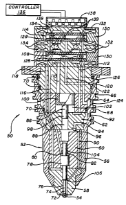
Figure 3 is a cross-sectional view of an embodiment
of a fuel injector of the present invention;
Figure 4 is a view similar to Fig. 3 showing the
fuel injector drawing in fuel;
Figure 5 is a view similar to Fig. 3 showing the
fuel injector ejecting the fuel;
Figure 6 is a cross-sectional view of an alternate
embodiment of the fuel injector.
DETAILED DESCRj~,'~"_ION OF THE INVENTION
One embodiment of the present invention is a fuel
injector which has check or needle valve that is
hydraulically controlled by a control fluid. A volume
of fuel is pressurized within a fuel chamber of the
injector by an intensifier. The check valve controls
the flow of fuel from the fuel chamber through one or


CA 02331163 2000-11-02
PCT~~ ~ ~ r ~ ~ ., ~ 6 -~
,~ , ., .. ~ . , ; ., 2000
-4-
more nozzle openings of a valve body. The flow of
control fluid is controlled by a control valve which can
move between a first position and a second position.
When the Control valve is at its first position, the
control fluid creates an hydraulic force which moves the
check valve to a closed position. When the control
valve is at its second position, the control fluid moves
the check valve to an open position to allow the
pressurized fuel to be ejected from the nozzle
opening(s). The intensifier can also be hydraulically
controlled by a control valve. The fuel injector does
not contain or utilize any mechanical return springs.
The absence of such springs increases the durability and
perfozmance repeatability of the injector.
Additionally, the positions of the check valve and the
intensifier can be rapidly changed by the hydraulic
forces of the control fluid to provide a high speed fuel
irijeCtor.
Referring to the drawzngs more particularly by
reference numbers, Figure 3 shows an embodiment of a
fuel injector 50 of the present invention. The injector
50 may include a valve body 52 which has at least one
nozzle opening or fuel spray orifice 54. The valve body
52 may include an outer shell 56 which supports a nozzle
tip 58, a piston block or spacer 60, a pair of
intensifier blocks or spacers 62 and 64 and a manifold
block 66. The valve body 52 may be attached to an
engine cylinder head (not shown) and extend directly
into an internal combustion chamber (not shown). The
shell 56 may have a number of outer circumferential
grooves 68 that retain 0-rings (not shown) which seal
the injector 50 to the engine cylinder head.
Additionally, the injector 50 may contain a number of
internal 0-rings 70 that seal the blocks 62, 64 and 66
to the shell 56.
~~~~.l~wr~ n' ~rf~ ,r
'd 06~C 'ON W~ - Z'~158 Wd6ti~Z OOOZ '6 '~~d


CA 02331163 2000-11-02
WO 99/57430 PCTNS991096b9
-5
The injector 50 may include a check or needle valve
72 that controls the flow of a fuel through the nozzle
openings 54. The check valve 72 may have a needle
portion 74 located within a nozzle chamber 76 of block
58 and a piston portion 78 located within a piston
chamber 80 of block 60. The piston 78 and needle 74 may
be two separate pieces or one integral piece.
The piston chamber 80 may receive a control fluid
which exerts an hydraulic force on either a first
surface 82 of the piston 78 or a second surface 84 of
the piston 78. An hydraulic force exerted on the first
surface 82 moves the check valve 72 to a closed position
where it seats against the nozzle tip 58 and prevents
fuel from being ejected from the injector 50. An
hydraulic force exerted on the second surface 84 moves
the check valve 72 to an open position and allows fuel
to flow through the nozzle openings 54.
The injector 50 may include an intensifier 86 which
pressurizes a fuel located within a fuel chamber 88.
The fuel chamber 88 communicates with the nozzle chamber
76 by a passage 90. The fuel chamber 88 may also
communicate with a fuel inlet port 92 by passage 94.
The passage 94 may contain a inlet check valve 96 which
prevents a reverse flow of fuel out through the inlet
port 92.
The intensifier 86 has a piston portion 98 located
within the fuel chamber 88 and a head portion 100
located within an intensifier chamber 102. The head
portion 100 has an effective surface area that is larger
than an effective surface area of the piston 98. The
differential area provides a mechanical gain so that an
hydraulic force exerted on the head 100 will move the
intensifier 86 from a first position to a second


CA 02331163 2000-11-02
WO 99/57430 PCT/US99/09669
-6-
position and pressurize the fuel within the fuel chamber
88.
The injector 50 may include a balance pin 104 that
communicates with the fuel chamber 88 and the piston 78
of the check valve 72. The pressure of the fuel on the
pin 104 offsets the hydraulic force exerted by the fuel
onto a shoulder 106 of the needle 74 to balance the
check valve 72 so that movement of the check valve 72 is
controlled by the net hydraulic force on the piston 78.
The movement of the intensifier 86 may be
controlled by a first control valve 108 that
communicates with the intensifier chamber 102 by
passages 110 and 112. The movement of the check valve
72 may be controlled by a second control valve 114 that
communicates with the piston chamber 80 by passages 116
and 118. The control valves 108 and 114 may both
communicate with a supply port 120 by a passage 122 and
a return port 124 by a passage 126. The supply port 120
may communicate with a rail line (not shown) of an
engine which has a pressurized control fluid. The rail
line typically communicates with the output of a pump.
The control fluid may be the fuel or a separate
hydraulic fluid. The return port 124 typically
communicates with a drain line which has a relatively
low pressure.
Each valve 108 and 114 may have a spool 128 that
reciprocally moves within a valve housing 130 between a
first position and a second position. Each valve 108
and 114 may also have coils 132 and 134 that are coupled
to an electrical controller 136 through terminals 138.
The controller 136 selectively provides an electrical
current to one of the coils 132 and 134. The current
creates a magnetic field which pulls the spool 128
towards one of the positions.

CA 02331163 2004-04-26
_7_
The spool 128 and housing 130 are preferably
constructed from 4140 steel which will retain a residual
magnetism that is strong enough to maintain the position
of the spool 123 even when electrical current is no
longer provided to the coils 132 and 134. In this
manner, the controller I36 can switch the state of the
valves 108 and 114 with a digital pulse. The control
valves 108 and 114 may be similar to the valves
disclosed in U.S. Patent No. 5,640,987 issued to
S turman.
The spools 128 preferably have outer grooves 139
which create a four-way valve. When the spool 128 of
the first valve 108 is at its the first (e. g. rightward)
position, the outer grooves 139 provide fluid
communication between passage 112 and the supply port
120, and fluid communication between the passage 110 and
the return port 124 to force the intensifier 86 to its
first position. When the spool 128 of the first valve
108 is at its second (e.g. leftward) position, the
passage 110 is in fluid communication caith the supply
port 120 and the passage 112 is in fluid communication
with the return port 124 so that the intensifier 86 is
moved to its second position to pressurize the fuel.
When the spool 128 of the second control valve 114
is at its first position, the passage 116 is in fluid
communication with the supply port 120 and the passage
118 is in fluid communication with the return port 120
so that the check valve 72 is pushed into the closed
position. Wren the spool 128 of the second control
valve 114 is at its second position the passage 116 is
in fluid communication with the return port 124 and the
passage 118 is in fluid communication with the supply
part 120 so that the check valve 72 is moved to its open
position.


CA 02331163 2000-11-02
'i, A lw.~~r
~~'.~,.<"~.',"-'a -a-
!~ U !~~
-s-
As shown in Figure 4, in operation, the spool 128
of the first control valve 108 is switched from its
second position to its first position to move the
intensifier 86 from its second position to its first
position. The (e. g. upward) movement of the intensifier
86 expands the fuel chamber 88 and draws in fuel through
the inlet port 92 and the check valve 96. The spool 128
of the first control valve 108 is typically maintained
at its closed position to prevent fuel from flowing
through the noazle opening 54.
As shown in Figure 5, to eject or spray fuel from
the injector 50, the spool 128 of the second control
valve 114 is switched from its first position to its
second position. The intensifier 86 is moved to its
second (e. g. downward) position to pressurize the fuel
within the fuel chamber 88. The check valve 72 is moved
to its open position to allow the pressurized fuel to
flow through the nozzle openings) 54. The spool 128 of
the respective control valves 108 and 114 are then
switched to their respective first positions and the
cycle is repeated.
w Figure 6 shows an alternate embodiment of a fuEl
injector 50'. In this embodiment the supply passage 122
communicates with the piston chamber 80 by passage 122'.
The check valve 72 is biased towards its closed position
by the effective pressure of the control fluid in the
piston chamber 80. When the intensifiEr 86 is moved to
its second position, the pressure of the fuel is much
greater than the pressure of the control fluid, so that
the fuel pressure pushes the check valve '12 away from
the nozzle openings) 54. When the intensifier 86
returns to its first position (e.g. upward), the
pressure of the fuel drops and the pressure of the
9 'd 06SL 'ON W~ - Z'81S8 Wd6~ ~ Z OOOZ '6 '~~d


CA 02331163 2000-11-02
WO 99/57430 PCT/US99/09669
_g_
working fluid within the passage 122' moves the check
valve 78 and closes the nozzle 54.
~nTtiile certain exemplary embodiments have been
described and shown in the accompanying drawings, it is
to be understood that such embodiments are merely
illustrative of and not restrictive on the broad
invention, and that this invention not be limited to the
specific constructions and arrangements shown and
described, since various other modifications may occur
to those ordinarily skilled in the art.

Representative Drawing
A single figure which represents the drawing illustrating the invention.
Administrative Status

For a clearer understanding of the status of the application/patent presented on this page, the site Disclaimer , as well as the definitions for Patent , Administrative Status , Maintenance Fee  and Payment History  should be consulted.

Administrative Status

Title Date
Forecasted Issue Date 2007-04-10
(86) PCT Filing Date 1999-05-03
(87) PCT Publication Date 1999-11-11
(85) National Entry 2000-11-02
Examination Requested 2004-04-19
(45) Issued 2007-04-10
Deemed Expired 2009-05-04

Abandonment History

There is no abandonment history.

Payment History

Fee Type Anniversary Year Due Date Amount Paid Paid Date
Application Fee $300.00 2000-11-02
Maintenance Fee - Application - New Act 2 2001-05-03 $100.00 2000-11-02
Maintenance Fee - Application - New Act 3 2002-05-03 $100.00 2002-04-05
Maintenance Fee - Application - New Act 4 2003-05-05 $100.00 2003-04-16
Request for Examination $800.00 2004-04-19
Maintenance Fee - Application - New Act 5 2004-05-03 $200.00 2004-04-19
Maintenance Fee - Application - New Act 6 2005-05-03 $200.00 2005-03-24
Maintenance Fee - Application - New Act 7 2006-05-03 $200.00 2006-04-04
Final Fee $300.00 2007-01-19
Maintenance Fee - Patent - New Act 8 2007-05-03 $200.00 2007-04-12
Owners on Record

Note: Records showing the ownership history in alphabetical order.

Current Owners on Record
STURMAN, ODED E.
Past Owners on Record
None
Past Owners that do not appear in the "Owners on Record" listing will appear in other documentation within the application.
Documents

To view selected files, please enter reCAPTCHA code :


To view images, click a link in the Document Description column. To download the documents, select one or more checkboxes in the first column and then click the "Download Selected in PDF format (Zip Archive)" or the "Download Selected as Single PDF" button.

List of published and non-published patent-specific documents on the CPD .

If you have any difficulty accessing content, you can call the Client Service Centre at 1-866-997-1936 or send them an e-mail at CIPO Client Service Centre.


Document
Description 
Date
(yyyy-mm-dd) 
Number of pages   Size of Image (KB) 
Description 2000-11-02 9 401
Abstract 2000-11-02 1 79
Claims 2000-11-02 8 296
Drawings 2000-11-02 5 232
Representative Drawing 2001-03-06 1 26
Cover Page 2001-03-06 2 78
Description 2004-04-26 9 382
Representative Drawing 2006-10-26 1 20
Cover Page 2007-03-22 2 62
Fees 2005-03-24 1 33
Assignment 2000-11-02 4 135
PCT 2000-11-02 15 578
Fees 2003-04-16 1 33
Fees 2002-04-05 1 38
Prosecution-Amendment 2004-04-19 1 31
Prosecution-Amendment 2004-04-26 4 142
Fees 2004-04-19 1 34
Fees 2006-04-04 1 34
Correspondence 2007-01-19 1 44
Fees 2007-04-12 1 43