Language selection

Search

Patent 2331247 Summary

Third-party information liability

Some of the information on this Web page has been provided by external sources. The Government of Canada is not responsible for the accuracy, reliability or currency of the information supplied by external sources. Users wishing to rely upon this information should consult directly with the source of the information. Content provided by external sources is not subject to official languages, privacy and accessibility requirements.

Claims and Abstract availability

Any discrepancies in the text and image of the Claims and Abstract are due to differing posting times. Text of the Claims and Abstract are posted:

  • At the time the application is open to public inspection;
  • At the time of issue of the patent (grant).
(12) Patent: (11) CA 2331247
(54) English Title: SKID WRAP ROLLER
(54) French Title: ROULEAU DE SERRAGE POUR ENVELOPPER DES PLATES-FORMES
Status: Term Expired - Post Grant Beyond Limit
Bibliographic Data
(51) International Patent Classification (IPC):
  • B65H 75/34 (2006.01)
  • B65B 11/00 (2006.01)
  • B65B 41/12 (2006.01)
(72) Inventors :
  • PHERO, NELSON (United States of America)
(73) Owners :
  • NELSON PHERO
(71) Applicants :
  • NELSON PHERO (United States of America)
(74) Agent: AVENTUM IP LAW LLP
(74) Associate agent:
(45) Issued: 2007-04-17
(22) Filed Date: 2001-01-17
(41) Open to Public Inspection: 2002-04-20
Examination requested: 2001-01-17
Availability of licence: N/A
Dedicated to the Public: N/A
(25) Language of filing: English

Patent Cooperation Treaty (PCT): No

(30) Application Priority Data:
Application No. Country/Territory Date
09/693,096 (United States of America) 2000-10-20

Abstracts

English Abstract

A tool used for wrapping boxes or shipments with plastic or other wrap in an ergonomic manner, as in warehouses or shipping departments. The tool is enlongated and allows the user to rotate about the object to be wrapped. A tensioner makes it possible for the user to ensure that the wrapping is taught. A stopper allows the tool to come into contact with the ground.


French Abstract

Un outil utilisé pour l'emballage des boîtes ou des envois avec une de la matière plastique ou un autre emballage d'une manière ergonomique, comme dans les entrepôts ou les services d'expédition. L'outil est allongé et permet à l'utilisateur de tourner autour de l'objet à envelopper. Un tendeur permet à l'utilisateur de s'assurer que l'emballage est réalisé. Une butée permet à l'outil d'entrer en contact avec le sol.

Claims

Note: Claims are shown in the official language in which they were submitted.

CLAIMS:
1. A skid wrap roller for holding a spool of wrap comprising:
a pole:
a tensioner fixedly attached onto said pole at a bottom end of said
pole;
a plate attached above said tensioner on said pole;
a plug attached above said plate on said pole ; and
wherein the spool of wrap is mounted on said pole, between said
plate and said plug.
2. The skid wrap roller of claim 1, wherein said tensioner can move
nearer to and farther from said plate via threads on said pole.
3. The skid wrap roller of claim 1, wherein when said tensioner moves
closer to said plate, said plate applies pressure to the spool of wrap.
4. The skid wrap roller of claim 1, wherein when said tensioner moves
farther from said plate, said plate releases pressure from the spool
of wrap.
5. A skid wrap roller for holding a spool of wrap comprising:
a pole;
a stopper fixedly attached onto said pole at a bottom end of said
pole;
a plate attached above said stopper on said pole;
a plug attached above said plate on said pole; and
wherein the spool of wrap is mounted on said pole, between said
-8-

plate and said plug.
6. The skid wrap roller of claim 5, wherein said stopper is rubber.
7. The skid wrap roller of claim 5, wherein said plate applies pressure
to the spool of wrap.
8. The skid wrap roller of claim 5, wherein said plate releases pressure
from the spool of wrap.
9. A skid wrap roller for holding a spool of wrap comprising:
a pole;
a tensioner fixedly attached onto said pole at a bottom end of said
pole;
a plate attached above said tensioner on said pole;
a plug attached above said plate on said pole;
a brake assay attached on said plug; and
wherein the spool of wrap is mounted on said pole, between said
plate and said plug.
10. The skid wrap roller of claim 9, wherein said plate applies pressure
to the spool of wrap.
11. The skid wrap roller of claim 9, wherein said plate releases pressure
from the spool of wrap.
12. The skid wrap roller of claim 9, wherein said brake assay frictionally
engages said spool and subsequently prevents the spool of wrap
from turning.
-9-

Description

Note: Descriptions are shown in the official language in which they were submitted.


CA 02331247 2001-O1-17
Nelson E. Phero
43 Beebetown Road
Hammontown, NJ 08037
SKID WRAP ROLLER
FIELD OF THE INVENTION
The present invention is relative to an invention which facilitates the
process of wrapping
skids in such a manner so as to secure their contents without causing
potential injury or harm to
the laborer.
BACKGROUND OF THE INVENTION
The packing industry is renowned for the back injuries and muscle strains that
often
afflict its laborers and packers. Improvements geared toward the ergonomics of
motion are often
overlooked where manual laborers are concerned. The current invention is
related to the field of
skid wrapping which is integral to t:he freight or packing and shipping
industries.
None of the relevant art, consisting of plastic wrap devices for wrapping
"skids", have
- 1 -

CA 02331247 2003-09-30
resolved the need for the operator to wrap skids from au awkward, bent over
position, that
~~cncrally puts strain on the spinal alignment and other muscles. furthermore,
smaller loads,
which arc too low to manipulate, also pose safety risks for the designated
wrappers; although this
type of load is generally placed on a forklift or electric lift to increase
accessibility, the skid
wrappers must often pass their arms and sometimes head beneath the skid in
order to completely
w°rap the goods.
U.S. Patent 4,102,513 issued to Twyman Guard on September 14, 1997 describes a
hand-held
apparatus which is used to wrap plastic stretch film around an object. Unlike
the present
invention, Guard's device has a short handle which still requires the laborer
to enter into
awkward and possibly dangerous situations in order to surround the object with
this fillll
material.
U.S. Patent 4,535,951 issued to Paul K. Riemenschneider, III on August 20,
1985 describes an
object useful in wrapping objects with a stretch film as well. This device,
however, involves a
mechanism in which a film roll with a tubular rigid core is clamped in between
a pair of opposed
core holders. A tension control assembly between the core and the core holders
is responsible for
adjustment of tension in the wrap during the wrapping process. Unlike the
present invention,
Riemenschrleider's device does not provide an easier method to wrap the object
which is
beneficial to the health and safety of the laborer. Due to the design of the
present invention, a
user may wrap well above and below regular reach eliminating undue tension
from bending aIld
standing on toes to reach low and high objects respectively.
- 2 -

CA 02331247 2001-O1-17
Nelson E. Phero
43 Beebetown Road
Hammontown, NJ 08037
SUMMARY OF THE INVENTION
The present invention is a device that is safer and more convenient for the
operator to use
than conventional wrapping methods. More specifically, the present invention
is a skid wrap
roller device which enables the operator to wrap skids from a safe position
minimizing the risk of
strain or other injury to life and limb. The present invention includes a
pole, with a stop on one
side, inserted into the hollow center of a spool of plastic wrap. The present
invention provides
the user greater control of the wrapping process while operating the device
from a standing
position.
The general structure of the present invention is a 60" wooden or hollow metal
pole ('/2"
dia.) with a 6" diameter plastic base and rubber stopper at one end. A
standard-sized plastic wrap
spool can be slid onto the pole from the other (unstoppered) end. The extended
pole functions in
like manner to a broom handle, enabling the operator to grasp the tool and
manipulate the
direction of the wrap from the top end (analogous to the broom handle), while
the plastic wrap
unrolls from the spool at the bottom end (where the broom head would be),
ultimately reaching
the desired goal of completely encasing the skid.
The wrap circumvents all elements which are placed upon the skid in an
organized and
uncompromising fashion to the laborer's well-being. The skid wrapper will be
at less risk for
potential back and neck pain as well as spinal misalignment.
- 3 -

CA 02331247 2001-O1-17
Nelson E. Phero
43 Beebetown Road
Hammontown, NJ 08037
BRIEF DESCRIPTION OF THE DRAWINGS
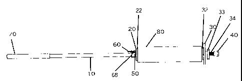
Figure 1 is a side view of the present invention.
Figure 2 is an exploded view of the brake assay.
DETAILED DESCRIP'CION OF THE PREFERRED EMBODIMENT
The present invention has a long wooden or metal pole (10), as shown Figure 1,
which is
approximately 60" long; a foam grip (70) is disposed at the end of the pole (
10). The long length
of the pole (10) allows the laborer to hold the device and extend a spool (80)
of wrap over an
area to be covered without the laborer bending down and twisting the laborer's
body in an
awkward position. The length of the: present invention eliminates squatting or
climbing to
properly wrap beds of items, and eliminates conventional ladder use in most
wrapping due to
height, because the spool (80) is disposed far along pole (10).
The pole ( 10) is inserted into spool (80) of wrapping material. Spool (80) is
hollow. The
diameter of 1 inch in the pole (10) provides for versatile use regarding
different size spools (80)
of wrapping material. Sleeve (68) is mounted atop pole (10) and has holes (50)
along the
- 4 -

CA 02331247 2001-O1-17
Nelson E. Phero
43 Beebetown Road
Hammontown, NJ 08037
diameter to act as attachments for a conventional cotter pin (not shown). The
holes (50) are
positioned along sleeve (68) for a 20~", 18", 15", or I 2" spool (80) of wrap,
and corresponding
holes (not shown) are similarly positioned along pole (10). It is contemplated
that variously
positioned holes (50) can be positioned along sleeve (68), and corresponding
holes (not shown)
can be similarly positioned along pole (10) depending on the length of a
particular spool (80)
chosen to be employed with the present invention. 'fhe hollow pole (10) serves
as an axis about
which the spool of wrap (80) can rotate. The smooth surface of the pole ( 10)
allows for
accelerated turning of the spool, and easier, expedited completion of the
wrapping.
A stopper (40), preferably m;~de of rubber, is continuous with a first end of
the pole (10).
The use of rubber for the stopper (4C1) allows easy turning access if the
first end is placed on
warehouse floors, loading docks or truck trailer beds while wrapping. The
stopper (40) also
protects low ceilings from marring as would happen with an unprotected end.
The stopper (40)
also acts as a safety measure to word;ers around the user if the present
invention is extended in a
somewhat horizontal manner from the objects being wrapped (not shown). Risk
for injury is
minimized by use of the stopper (40) if collision with other laborers should
occur.
Tension from a circular plate; (30) on the bottom side of the spool (80) and
circular plug
(20) on the top side of the spool (80) of wrap allow for secure and taut
wrapping of the objects
being wrapped (not shown). The circular plate (30) acts as a seat for an end
of the spool (80) of
wrap. The circular plug (20) also acia as a friction point to assist in the
unraveling of the spool
(80) of wrap. The plug (20) and plate (30) secure the spool (80) of wrap on
the pole (10). The
- 5 -

CA 02331247 2001-O1-17
Nelson E. Phero
43 Beebetown Road
Hammontown, NJ 08037
circular plug (20) is easily removed for spool (80) replenishment. 'The plate
(30) and plug (20)
are preferably fabricated of heavy plastic that is durable and easy to clean
if necessary. In the
preferred embodiment of the presenl: invention, there are no bolts or screws
necessary for
attachment of plug (20) or plate (30). Plug (20) and plate (30) are separated
from spool (80) via
plug ring (22) and plate ring (32), respectively, which function like
conventional washers.
Between plate (30) and stopper (40) are threads (34) which are part of pole
(10). Threads
(34) serve as a mounting point for tensioner (33), which is threaded on
threads (34). Depending
on the amount of resistance desired ;as the laborer turns spool (80), the
tensioner (33) can be
turned on threads (34) to apply pressure to plate (30) and cause spool (80) to
turn more slowly, or
tensioner (33) can be turned on threads (34) to remove pressure fram plate
(30) and cause spool
(80) to turn more quickly.
Also included in the present invention is a brake assay (58) shown in Figure 2
as an
exploded view. The brake assay (58) works much like a bicycle brake, in that
it has an arm (60)
that can be depressed to stop the flow of the spool (80) of wrap around an
object (not shown)
being wrapped. The laborer completes the final wrapping motion around the
object being
wrapped and depresses the arm (60) so that it frictionally engages spool (80)
to prevent spool
(80) from moving. 'the laborer can easily cut the spool (80) of wrap from the
object being
wrapped with a tearing motion. The assay (60) enables the laborer to be
efficient in the quantity
of the wrap on the spool (80). Arm (60) pivots within channel (65), the second
part of the assay
(58), so that arm (60) that can be depressed to stop the turning of the spool
(80). The third part
- 6 -

CA 02331247 2001-O1-17
Nelson E. Phero
43 Beebetown Road
Hammontown, NJ 08037
of the assay (60) is the sleeve (68) ~~hich fits around pole (10). The sleeve
(68) provides a
mounting surface for the channel (6_'i), and sleeve (68) rotates about pole
(10).
The present invention can be utilized to assist in wraps above and below the
laborers
normal grasp of reach. The long lenl;th of the pole ( 10) allows for easy
access to high beds of
objects, while still having versatility in objects low to the ground or on the
floor. The
elimination of kneeling and squatting to wrap objects will greatly reduce
discomfort and possible
injury in the wrapping process.
Primarily, the present invention is intended to be used in the wrapping of
items with a
hand held non-motorized device, as in a warehouse for shipping or storing. It
is to be understood
that the present invention is not limited to the sole embodiment described
above, but
encompasses any and all embodiments within the scope of the following claims.

Representative Drawing
A single figure which represents the drawing illustrating the invention.
Administrative Status

2024-08-01:As part of the Next Generation Patents (NGP) transition, the Canadian Patents Database (CPD) now contains a more detailed Event History, which replicates the Event Log of our new back-office solution.

Please note that "Inactive:" events refers to events no longer in use in our new back-office solution.

For a clearer understanding of the status of the application/patent presented on this page, the site Disclaimer , as well as the definitions for Patent , Event History , Maintenance Fee  and Payment History  should be consulted.

Event History

Description Date
Revocation of Agent Requirements Determined Compliant 2022-01-27
Appointment of Agent Requirements Determined Compliant 2022-01-27
Inactive: Expired (new Act pat) 2021-01-18
Common Representative Appointed 2019-10-30
Revocation of Agent Request 2018-06-06
Inactive: Adhoc Request Documented 2018-06-06
Appointment of Agent Request 2018-06-06
Revocation of Agent Requirements Determined Compliant 2018-05-18
Appointment of Agent Requirements Determined Compliant 2018-05-18
Revocation of Agent Requirements Determined Compliant 2009-07-07
Inactive: Office letter 2009-07-07
Appointment of Agent Requirements Determined Compliant 2009-07-07
Appointment of Agent Request 2009-06-16
Revocation of Agent Request 2009-06-16
Small Entity Declaration Determined Compliant 2008-01-17
Grant by Issuance 2007-04-17
Inactive: Cover page published 2007-04-16
Inactive: Final fee received 2007-02-01
Pre-grant 2007-02-01
Notice of Allowance is Issued 2006-10-02
Letter Sent 2006-10-02
Notice of Allowance is Issued 2006-10-02
Inactive: Approved for allowance (AFA) 2006-09-20
Amendment Received - Voluntary Amendment 2006-03-29
Inactive: S.30(2) Rules - Examiner requisition 2005-10-17
Amendment Received - Voluntary Amendment 2004-10-15
Inactive: S.30(2) Rules - Examiner requisition 2004-04-16
Inactive: S.29 Rules - Examiner requisition 2004-04-16
Amendment Received - Voluntary Amendment 2003-09-30
Inactive: S.30(2) Rules - Examiner requisition 2003-03-31
Application Published (Open to Public Inspection) 2002-04-20
Inactive: Cover page published 2002-04-19
Inactive: First IPC assigned 2001-04-10
Inactive: IPC assigned 2001-04-10
Inactive: First IPC assigned 2001-04-10
Inactive: IPC assigned 2001-03-22
Inactive: Filing certificate - RFE (English) 2001-02-16
Application Received - Regular National 2001-02-15
Request for Examination Requirements Determined Compliant 2001-01-17
All Requirements for Examination Determined Compliant 2001-01-17

Abandonment History

There is no abandonment history.

Maintenance Fee

The last payment was received on 2007-01-17

Note : If the full payment has not been received on or before the date indicated, a further fee may be required which may be one of the following

  • the reinstatement fee;
  • the late payment fee; or
  • additional fee to reverse deemed expiry.

Patent fees are adjusted on the 1st of January every year. The amounts above are the current amounts if received by December 31 of the current year.
Please refer to the CIPO Patent Fees web page to see all current fee amounts.

Fee History

Fee Type Anniversary Year Due Date Paid Date
Application fee - small 2001-01-17
Request for examination - small 2001-01-17
MF (application, 2nd anniv.) - small 02 2003-01-17 2003-01-07
MF (application, 3rd anniv.) - small 03 2004-01-19 2004-01-07
MF (application, 4th anniv.) - small 04 2005-01-17 2005-01-14
MF (application, 5th anniv.) - small 05 2006-01-17 2006-01-17
MF (application, 6th anniv.) - small 06 2007-01-17 2007-01-17
Final fee - small 2007-02-01
MF (patent, 7th anniv.) - small 2008-01-17 2008-01-17
MF (patent, 8th anniv.) - small 2009-01-19 2009-01-19
MF (patent, 9th anniv.) - small 2010-01-18 2009-11-17
MF (patent, 10th anniv.) - small 2011-01-17 2011-01-17
MF (patent, 11th anniv.) - small 2012-01-17 2011-10-21
MF (patent, 12th anniv.) - small 2013-01-17 2012-11-08
MF (patent, 13th anniv.) - small 2014-01-17 2013-10-24
MF (patent, 14th anniv.) - small 2015-01-19 2014-09-26
MF (patent, 15th anniv.) - small 2016-01-18 2015-11-12
MF (patent, 16th anniv.) - small 2017-01-17 2016-10-06
MF (patent, 18th anniv.) - small 2019-01-17 2017-10-19
MF (patent, 17th anniv.) - small 2018-01-17 2017-10-19
MF (patent, 19th anniv.) - small 2020-01-17 2017-10-19
Owners on Record

Note: Records showing the ownership history in alphabetical order.

Current Owners on Record
NELSON PHERO
Past Owners on Record
None
Past Owners that do not appear in the "Owners on Record" listing will appear in other documentation within the application.
Documents

To view selected files, please enter reCAPTCHA code :


To view images, click a link in the Document Description column. To download the documents, select one or more checkboxes in the first column and then click the "Download Selected in PDF format (Zip Archive)" or the "Download Selected as Single PDF" button.

List of published and non-published patent-specific documents on the CPD .

If you have any difficulty accessing content, you can call the Client Service Centre at 1-866-997-1936 or send them an e-mail at CIPO Client Service Centre.


Document
Description 
Date
(yyyy-mm-dd) 
Number of pages   Size of Image (KB) 
Representative drawing 2002-03-24 1 4
Description 2003-09-29 7 236
Claims 2003-09-29 2 51
Abstract 2001-01-16 1 12
Description 2001-01-16 7 239
Claims 2001-01-16 2 43
Drawings 2001-01-16 2 33
Claims 2004-10-14 2 47
Claims 2006-03-28 2 48
Representative drawing 2007-03-28 1 4
Filing Certificate (English) 2001-02-15 1 162
Reminder of maintenance fee due 2002-09-17 1 109
Commissioner's Notice - Application Found Allowable 2006-10-01 1 161
Fees 2003-01-06 1 46
Fees 2004-01-06 1 45
Fees 2005-01-13 1 50
Fees 2006-01-16 1 47
Fees 2007-01-16 1 47
Correspondence 2007-01-31 1 54
Fees 2008-01-16 1 50
Fees 2009-01-18 1 46
Correspondence 2009-06-15 2 62
Correspondence 2009-07-06 1 15
Correspondence 2009-07-06 1 14
Fees 2011-01-16 1 201