Note: Descriptions are shown in the official language in which they were submitted.
CA 02331267 2000-11-03
WO 99/56658 PCT/US99/09857
AUTOMATED TOOTH SHADE ANALYSIS AND MATCHING SYSTEM
This application claims the benefit of U.S. Provisional Application No.
60/084,354, filed May 5, 1998.
COPYRIGHT NOTICE
A portion of the disclosure of this patent document contains material which is
subject to copyright protection. The copyright owner has no objection to the
facsimile
reproduction by anyone of the patent document or the patent disclosure, as it
appears in
the Patent and Trademark Office patent file or records, but otherwise reserves
all
copyright rights whatsoever.
TECHNICAL FIELD
This invention relates in general to systems for color matching and, more
specifically, to systems for analyzing and matching tooth shades. Such systems
are of
particular use in manufacturing dental prosthetics (e.g., crowns, bridges,
veneers, and
prosthetic teeth) to repair, replace or alter natural teeth, in various dental
tooth
whitening procedures and to enable communication between patient, dentist and
lab
technician concerning such procedures.
BACKGROUND ART
Dentists often repair or replace a diseased, damaged, or unsightly natural
tooth
of a patient with a crown, bridge, veneer, or prosthetic tooth. One obvious
goal in
performing such a repair or replacement is to provide the patient with a
natural-looking
smile despite the presence of the prosthesis. Attempts to reach this goal
generally
involve matching the color of the prosthesis to the color of the natural tooth
being
repaired or replaced, and to the colors of the natural teeth that are adjacent
where the
prosthesis will be placed.
Similarly, dentists often perform various tooth whitening procedures on a
patient's natural teeth to reverse the effects of aging, coffee drinking,
smoking, and
similar activities on the patient's dental appearance. The goal in such
procedures is also
CA 02331267 2000-11-03
WO 99/56658 PCT/US99/09857
-2-
to provide the patient with a natural-looking smile, and attempts to reach
this goal also
generally involve color matching.
To this end, manufacturers of the various colored porcelains, resins,
compomers
ceramers or other direct restorative materials conventionally used in making
dental
prosthetics, or in repairing discolored, chipped, broken or malformed teeth,
typically
provide color matching shade guides to dentists which illustrate the various
colored
porcelains available. As shown in FIG. 1, one such shade guide 10 includes a
variety of
shade tabs 12, each made of a different colored porcelain available from a
manufacturer. A dentist determines the color of a patient's natural teeth by
detaching
individual shade tabs 12 from the shade guide 10 and holding the shade tabs 12
next to
the patient's natural teeth for comparison. Once a color match is found, the
dentist
orders a dental prosthesis from a dental laboratory in the matching colored
porcelain or
other material, or, if the patient's teeth are being whitened, the dentist
uses the color
match as a base against which to compare the eventual results of the whitening
process.
This somewhat rudimentary method often provides less than desirable results
because of the inaccuracy inherent in the dentist "eyeballing" the color
match. Poor
lighting, poor vision, eye fatigue, conflicting ambient colors or even lack of
patient
cooperation in the process, among other things, can cause the dentist to miss
the best
match. More importantly, the best match is often a combination of two or more
colored
porcelains, sometimes from different manufacturers, which is difficult to
discern by the
human eye.
Accordingly, a variety of mechanical and electronic devices have been devised
to aid in matching tooth shades. Some of these devices are described in U.S.
Patent
Nos. 5,766,006 to Murljacic, 5,759,030 to Jung et al., 5,690,486 to Zigelbaum,
5,529,492 to Yarovesky et al., 5,383,020 to Vieillefosse, 5,055,040 to Clar,
4,654,794
to O'Brien, and 4,110,826 to Mbllgaard. Unfortunately, none of these devices
has been
very successful in advancing the tooth shade matching process much beyond the
"eyeballing" procedure described above.
Therefore, there is a need in the art for an improved tooth shade matching
system.
CA 02331267 2000-11-03
WO 99/56658 PCT/US99/09857
-3-
DISCLOSURE OF INVENTION
In accordance with the present invention, a computer-aided system provides
apparatus and methods for capturing an image of a patient's teeth and
analyzing such
image with respect to the inherent tooth coloration and shading
characteristics of the
patient's teeth for the purposes of reproducing such inherent coloration and
shading in
restorative procedures and prosthetics.
In one embodiment of the invention, for example, a dental prosthesis for a
patient is made by acquiring at least one image of the patient's teeth which
contains
normalization references. The image is then normalized in accordance with the
normalization references. Next, the normalized image is standardized by
matching the
normalized image to selected shade standards, and the dental prosthesis is
then made in
accordance with the standardized image. The prosthesis may then be compared
with
the normalized image to assure a satisfactory product. The analysis and
matching
system of the present invention may be used not only in producing replacement
prosthetics, such as dentures, bridges or caps, but is used in the restoration
of broken,
chipped or otherwise damaged or malformed teeth.
In another embodiment of this invention, a patient's teeth are whitened by
acquiring at least one pre-whitening image of the patient's teeth, the image
containing
normalization references. The pre-whitening image is normalized in accordance
with
the normalization references contained therein, and the normalized pre-
whitening image
is then standardized by matching the normalized image to selected shade
standards.
The patient's teeth are then whitened. After whitening the patient's teeth, at
least one
post-whitening image of the patient's teeth containing normalization
references is
acquired, the post-whitening image is normalized in accordance with the
normalization
references contained therein, and the normalized post-whitening image is
standardized
by matching the normalized image to selected shade standards. Then, the
standardized
pre-whitening image and the standardized post-whitening image are compared.
In still another embodiment, image analysis is performed on a patient's teeth
by
acquiring at least one image of the patient's teeth containing normalization
references.
The image is then normalized in accordance with the normalization references
contained therein, and the normalized image is standardized by matching the
normalized image to selected shade standards. Communication between doctor,
patient
CA 02331267 2000-11-03
WO 99/56658 PCT/US99/09857
-4-
and lab technician is facilitated through the invention to provide each with
the ability to
select desired shades and/or colors of the eventual prosthesis, such as in
cases of dental
restoration where a full or partial set of dentures is being produced.
In a further embodiment of this invention, a computer-readable storage medium
stores a program for causing a computer to operate in accordance with the
method for
performing image analysis on a patient's teeth described immediately above.
In yet another embodiment, an apparatus for performing image analysis on a
patient's teeth includes an input device for acquiring at least one image of
the patient's
teeth, the image containing normalization standards. Another device coupled to
the
input device normalizes the image in accordance with the normalization
references
contained therein and matches the normalized image to selected shade standards
to
standardize the normalized image.
In an additional embodiment of this invention, an electronic system
incorporates
the apparatus described immediately above.
BRIEF DESCRIPTION OF DRAWINGS
FIG. 1 is a side view of a conventional shade guide;
FIG. 2A is a flow diagram illustrating a prosthetic tooth manufacturing method
of this invention;
FIG. 2B is a block diagram illustrating an electronic system implementing the
prosthetic tooth manufacturing method of FIG. 2A;
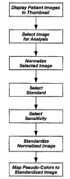
FIG. 3 is a flow diagram illustrating in more detail a patient image analysis
procedure of the prosthetic tooth manufacturing method of FIG. 2A;
FIG. 4 is a screen capture illustrating a thumbnail gallery patient image
display
step and a patient image selection step of the patient image analysis
procedure of FIG.
3;
FIGS. SA, SB, and SC are screen captures illustrating a patient image
normalization step of the patient image analysis procedure of FIG. 3;
FIGS. 6 is a screen capture illustrating a standards selection step of the
patient
image analysis procedure of FIG. 3;
CA 02331267 2000-11-03
WO 99/56658 PCT/US99/09857
-$-
FIGS. 7A and 7B are screen captures illustrating a standardization sensitivity
selection step and a standardization step of the patient image analysis
procedure of FIG. 3;
FIG. 8 is a screen capture illustrating a pseudo-color mapping step of the
patient
image analysis procedure of FIG. 3;
FIG. 9 is a screen capture illustrating a quality analysis step of the
prosthetic
tooth manufacturing method of FIG. 2A; and
FIG. 10 is a diagram illustrating a computer-readable storage medium storing
software implementing the prosthetic tooth manufacturing method of FIG. 2A.
BEST MODES FOR CARRYING OUT THE INVENTION
As shown in FIG. 2A, a method 20 for manufacturing a prosthetic tooth in
accordance with this invention begins with a dentist acquiring digital images
of a
patient's natural teeth. It should be noted that although this invention will
be described
with respect to the manufacturing of a prosthetic tooth or teeth, those having
skill in the
technical field of this invention will understand that the invention is
applicable to
manufacturing a wide variety of other dental prosthetics including, for
example,
crowns, bridges, removable dentures and veneers. Further, the invention
described
herein may be used for restoring a patient's natural teeth when, for example,
a tooth
becomes broken, chipped or modified from its original condition, thereby
requiring
some form of restoration, such as bonding or filling. It will also be
understood that
while a dentist will typically acquire the patient images, others may do so
instead
including, for example, a dental hygienist, assistant, or technician. Further,
it will be
understood that in some circumstances the "natural" teeth in the acquired
images may
actually include previously installed dental prosthetics.
As shown in FIG. 2B, the method 20 (FIG. 2A) is implemented, in part, in
software executing in an electronic system 22 comprising an input device 24,
an output
device 26, a processor device 28, and a memory device 30. The software may
preferably be a Windows 95~- or Windows98~-compatible, 32-bit stand-alone
application, but may instead be compatible with any other operating system or
environment including, for example, UNIX, LINUX, the Apple OS, Windows~ 3.x,
and
DOS. Also, the software may include, or be compliant with, ActiveX controls or
Java
CA 02331267 2000-11-03
WO 99/56658 PCT/US99/09857
-6-
Applets. The electronic system 22 is preferably an IBM-PC-compatible computer
system, but may instead comprise any other computer or electronic system.
The dentist acquires the patient teeth images using the input device 24, which
may be any suitable device for acquiring digital images including, for
example: a
standard or intra-oral analog color Charge Coupled Device (CCD) video camera
providing a video feed to a TWAIN-compliant frame captwe PC-card; a digital
camera
providing digital images directly to a 32-bit TWAIN driver through a SCSI
port; and a
color image scanner scanning photographic slides, pictwes, and the like and
providing
the resulting digital images directly to a 32-bit TWAIN driver through a SCSI
port. Of
cowse, the patient images may have previously been acquired and stored on a
storage
medium, such as a Jazz~ or Zip~ disc, in which case the dentist may
"reacquire" them
by transferring them from the storage medium to the electronic system 22.
In order to reduce shade variation in the patient images due to the camera
angle
at which the images are taken, it is preferable, but not necessary, that the
dentist use
standardized camera angles. For example, the dentist may take standard left,
right, and
straight-on pictures level with the patient's mouth. Of cowse, other
standardized angles
are also possible or helpful, such as inferior and superior angles.
Also, in order to reduce variations due to camera type, lighting conditions,
etc.,
the dentist inserts black and white reference tabs into the images to provide
references
with respect to which the images may be normalized, as will be described in
more detail
below with respect to FIGS. SA, SB, and SC. These black and white reference
tabs are
manufactwed using homogeneous, non-reflective porcelains, and are intended to
define
the respective minimum and maximum Red, Green, and Blue (RGB) values for each
image.
Referring once again to FIG. 2A, after acquiring the patient images, the
dentist
sends the images to a dental laboratory for analysis by a lab technician. Of
course, it
should be understood that while this invention will be described in the
context of a
dentist taking the pictwes and installing the prosthetic tooth and a lab
technician
performing the image analysis and manufactwing the prosthetic tooth, other
arrangements are possible. For example, the dentist might perform the image
analysis
and send the analyzed images to the dental technician, or the patient's images
may be
taken at the dental laboratory by the lab technician. Also, although the
description
CA 02331267 2000-11-03
WO 99/56658 PCT/US99/09857
herein implies a degree of physical distance between the dentist's office and
the dental
laboratory, the dentist and the laboratory may, in fact, reside in close
physical
proximity, including within the same offices. Thus, the dentist and the lab
technician
may use the same computer system if they are located in the same offices,
thereby
eliminating the need for the dentist to "send" the images to the lab
technician.
The dentist may send the patient images to a dental laboratory using a wide
variety of means including, for example, an e-mail, an Internet download, a
modem-to-
modem download, and delivery of a storage medium, such as a Jazz~ or Zip~
disc, on
which the images are stored.
Upon receiving the patient images, the lab technician analyzes the images
using
another electronic system 22 (FIG. 2B) adapted using software for his or her
use in
implementing another part of the method 20. As described herein, the dentist
and the
lab technician have nearly identical software executing on their respective
electronic
systems 22 (FIG. 2B). However, it will be understood that certain functions
desirable
in the lab technician's software (e.g., image analysis) may not be necessary
to the
dentist's software (and therefore may not be present therein), and vice-versa.
As shown in FIGS. 3 and 4, the lab technician begins analysis of the images by
displaying them in a thumbnail gallery 40. The lab technician then selects one
of the
images from the gallery 40 for analysis, and displays the selected image 42 in
large
format.
As shown in FIGS. 3, SA and SB, the lab technician continues the image
analysis procedure by normalizing the selected image 42. The lab technician
begins the
normalization process by selecting a "Set Black Reference" button 50, and then
adjusting and moving a selection area 52 so it identifies a black reference
tab 54
previously inserted into the selected image 42 by the dentist. With the black
reference
tab 54 identified, the software executing on the lab technician's system 22
(FIG. 2B)
then determines the Black Reference RGB value by determining the average red,
green,
and blue values among all the pixels in the selection area 52. A similar
procedure
involving a "Set White Reference" button 56, the selection area 52, and a
white
reference tab 58 allow for the determination of the average red, green, and
blue values
for a White Reference RGB value as well. The Black and White References may be
generally referred to as "normalization references."
CA 02331267 2000-11-03
WO 99/56658 PCT/US99/09857
_g_
With the Black and White Reference RGB values determined, the software then
calculates a normalized look-up table for the selected image 42. An example
may help
explain this aspect of the disclosure. Assume, for the moment, that each pixel
of the
selected image 42 is stored as an 8-bit index into a 256 color look-up table
such as the
following:
Index Red Green Blue
00000000 0000001000000101 00000001
00000001 0000010000000110 00000011
00000010 0000010100000111 00000101
11111110 1111011011111101 11111100
11111111 1111100111111110 11111111
Table 1
Under this circumstance, the software normalizes the look-up table by
recalculating the
red, green, and blue values for each index. The calculations are as follows:
New Red Value = (255 = Red Range) X (Index - Black Reference Red Value) + 0.5
(1)
New Green Value = (255 = Green Range) X (Index - Black Reference Green Value)
+ 0.5 (2)
New Blue Value = (255 = Blue Range) X (Index - Black Reference Blue Value) +
0.5 (3)
where
Red Range = White Reference Red Value - Black Reference Red Value (4)
Green Range = White Reference Green Value - Black Reference Green Value (5)
Blue Range = White Reference Blue Vaiue - Black Reference Blue Value (6)
Of course, images that directly store the red, green, and blue values for each
pixel (e.g., so-
called "24-bit" images), and that, therefore, do not use a look-up table, may
be normalized
in much the same way, except that the normalization procedure is performed on
the pixel
values of the image itself rather than on the values in a look-up table.
CA 02331267 2000-11-03
WO 99/56658 PCT/US99/09857
-9-
Continuing with the example described above, once the look-up table for the
selected image 42 is normalized, the selected image 42 is redisplayed as a
normalized
image 60, as shown in FIG. SC, using the normalized look-up table.
As shown in FIGS. 3 and 6, with the selected image 42 (FIG. SA) normalized,
the
S lab technician then selects the shade standards 62 to be used in
manufacturing the
prosthetic tooth. Although the shade standards can be generated from images of
the
conventional shade guides previously described, it is preferable that the
shade standards
be generated from flat, non-reflective, homogeneous porcelain samples. This is
because
the conventional shade guides are manufactured to look like a conventional
tooth, and thus
are curved, semi-glossy, and non-homogeneous in the porcelain shade they
represent.
Thus, for example, a conventional shade standard "a-1" shade tab is made to
look like a
tooth, so it is curved, semi-glossy, and is only a true "a-1" porcelain in its
center. The
preferred flat, non-reflective, homogeneous porcelain samples are better
adapted to provide
accurate shade standards for digital image analysis.
As shown in FIGS. 3, 7A, and 7B, with the shade standards selected, the lab
technician then selects a standardization sensitivity level using a
sensitivity selector 64, and
the software then attempts to match each pixel in the normalized image 60
(FIG. SC) to
one of the selected standards. To accomplish this for each pixel, the software
calculates
a "distance" between the RGB values of the pixel and the RGB values of each of
the
selected standards, according to the following equation:
distance = (~xel - d~2 + lGpixel ' Gatandvd~z + (Bpixel - Bstendud~z
The software then determines the standard having the minimum distance
calculated. If
this minimum distance does not exceed the sensitivity level (e.g., 4,000) set
by the lab
technician, the software determines that the standard with the minimum
distance
matches the pixel and assigns this standard color to the pixel. If, instead,
the software
determines that the minimum distance calculated exceeds the sensitivity level
selected,
then the software assigns the color black to the pixel. As shown in FIG. 7A,
the
software then displays a standardized image 66 with the colors assigned to
each pixel.
It should be noted that the standardized image 66 is displayed alongside a
statistical analysis 68 of the percentage of the image 66 occupied by the
various
CA 02331267 2000-11-03
WO 99/56658 PCT/US99/09857
-10-
standards. As shown in FIG. 7B, this statistical analysis 68 can also be
confined to a
selected region 70.
As shown in FIG. 8, pseudo-colors can be assigned to each standard to generate
a pseudo-color image 80 in which the differences between various standards is
easier to
discern than in the standardized image 70 of FIG. 7B. Thus, for example, a
standard
shade "a-1 ", which may be a light tan color, may be assigned a pseudo-color
of yellow,
while a standard shade "a-2", which may be a slightly darker tan color, may be
assigned
a pseudo-color of grass green. As a result, while the distinctions between a-1
(light tan
color) and a-2 (slightly darker tan color) may be difficult to discern from
the
standardized image 70, they readily stand out in the pseudo-color image 80
because of
the contrasting yellow and grass green colors.
As shown in FIG. 2A, once the patient images have been analyzed, the lab
technician manufactures the prosthetic tooth using the pseudo-color image 80
(FIG. 8)
as a guide.
As shown in FIGS. 2A and 9, the lab technician then analyzes the quality of
the
prosthetic tooth 90 by comparing a normalized image of the prosthetic tooth 90
with the
normalized image 60 of the patient's natural tooth using the software.
Specifically, the
technician selects the natural tooth and the prosthetic tooth using selection
regions 92
and 94, and the software then calculates the average difference 9b in shades
between
the two regions 92 and 94. A dentist may specify that the prosthetic tooth
must not
exceed a certain maximum average difference (e.g., 10%), and the dental
laboratory
may charge different fees for prosthetic teeth guaranteed to fall below
certain maximum
average differences (e.g., $500 for 2%, $300 for 5%, $150 for 10%, etc.).
Once the lab technician has confirmed that the prosthetic tooth meets the
specified quality standard, the technician can send an image of the prosthetic
tooth to
the dentist so the dentist can confirm the quality of the tooth using his own
software in
the same manner as described immediately above. The dentist can then contact
the
patient so that the dentist and patient can confer and agree as to the
acceptability of the
prosthesis. The dentist may confer in-person with the patient or may transmit
the image
to the patient be electronic mail for review and discussion. If changes are
required,
those can be conveyed to the Iab technician for implementation into the image
for final
review before the actual prosthetic tooth is completed. Once the dentist
authorizes
CA 02331267 2000-11-03
WO 99/56658 PCT/US99109857
-I 1-
delivery of the prosthetic tooth, the lab technician sends the tooth to the
dentist, and the
dentist installs the tooth in the patient.
It should be understood that while this invention has been described with
respect
to a process for manufacturing a prosthetic tooth or bridge or dentures, the
system is
equally applicable to restoration of teeth in the dentist's office when, for
example, a
patient's tooth is broken, chipped or otherwise modified from its original
condition, and
in such instances, the dentist may prepare the image and analyze it within his
office to
determine an accurate restoration of the tooth. The system of the invention is
equally
applicable to a process for teeth whitening. In such a process, the image
analysis
procedures described herein are used to determine the shade of a patient's
teeth, and
then to compare the shade of the post-whitening teeth to the shade of the pre-
whitening
teeth.
It should also be understood that while this invention has been described with
respect to colors described in the RGB format, the invention may alternatively
incorporate any other applicable format for describing colors including, for
example,
the Hue, Saturation, and Luminance (HSL) or Hue, Value and Chroma format.
As shown in FIG. 10, a computer-readable storage medium 100 stores the
software previously described. The storage medium 100 may be, for example, a
floppy
disc, a Jaz~ or Zip~ disc, a hard drive, a CD-ROM, a DVD-ROM, a flash EEPROM
card, a magnetic tape, or a ROM, PROM, EPROM, EEPROM, or flash EEPROM chip.
Although this invention has been described with reference to particular
embodiments, the invention is not limited to these described embodiments. For
example, while the various steps and procedures of the methods of this
invention have
been described as occurring in a particular order, the invention is not
limited to the
described order. Rather, the invention is limited only by the appended claims,
which
include within their scope all equivalent devices or methods that operate
according to
the principles of the invention as described.