Note: Descriptions are shown in the official language in which they were submitted.
CA 02331307 2003-08-11
TUBE CUTTER
The present invention relates to the field of tube cutting and more
particularly to a tube cutter
having an automatic feed as the cutter is rotated for the purpose of cutting
through the tube.
CA 02331307 2004-02-04
BACKGROUND OF INVENTION
Tube cutters are well known in the field and are generally constructed to
allow movement of
the cutting wheel into the tube by manually advancing the cutting wheel
inwardly during the cutting
operation. Such devices are awkward to use and require constant operator
attention, as well as skill.
Consequently, it has become somewhat common to provide a tube cutter in which
the rotating cutting
wheel is automatically fed into the tube as it is being cut. This provides a
tube cutter that is easily and
quickly positioned for use. Such tube cutter only requires turning of the
cutter around the tube in order
to complete the cutting operation once the cutter has been positioned on the
tube. This rotating action
can be manual or can be by a power drive as shown in Kritchever U.S. Patent
No. 5,495,672 issued
March 5, 1996. The difficulty is that the various structures for accomplishing
the automatic feeding of
cutting wheel into the tube during the rotating cutting action have
advantages, but present distinct
disadvantages. For instance, when the automatic advancing cutter is in a clam
shell frame, as shown
in Condon U.S. Patent No. 2,448,578 issued September 7, 1948 or Collier U.S.
Patent No. 5,903,980
issued May 18, 1999, the size of the frame is dictated by the size of the tube
being cut. Consequently,
each tube size requires its own cutter. The amount of spring force exerted
during the cutting operation
is dictated by the size of the clam shell frame. Minor differences in the
diameter of the tube can not be
accommodated in such fixed frame rotary tube cutters. These cutters are thus
dedicated tools and can
not be used universally. Another type of tube cutter that is generally
2
CA 02331307 2004-02-04
size specific is shown in McDaniel U.S. Patent No. 5,206,996 issued May 4,
1993. The diameter of
the tube being cut dictates the size of the U-shaped frame for carrying the
support rollers and the spring
biased cutter. With this fixed frame tube cutter, there is no easy way to
accommodate different tube
sizes. As the spring loses its spring force during long-term use or in
temperature changes, the cutting
action is drastically affected. This is also true of the encircling frame type
of tool. Each of these cutters
is tube size specific and susceptible to changes in the spring biased cutter
to alter the efficiency and
effectiveness of the cutting action. McDaniel recognizes the disadvantage of
fixed frame tube cutter by
suggesting a tube cutter involving a spring biased lever system wherein one
blade of the system carries
the support rolls and the other blade carries the rotating cutter wheel. This
attempt to rectify the
IO problems associated with a fixed frame tube cutter is not successful for
many reasons. It includes
protruding handles and a pivoting infeed of the rotating cutter wheel that
changes the cutting action and
spring force according to the diameter of the tube being cut.
The disadvantages of tube cutters that automatically feed the cutter wheel
into the tube during
cutting, but are size specific, was generally solved in 1934. In Myers U.S.
Patent No. 1,945,949 issued
February 6, 1934, a first frame carries the two tube support rollers. The
other frame rotates the rotating
cutter wheel about a fixed axis and is pulled toward the first frame by a
threaded shaft. To load the
cutter for automatic feeding, the shaft is connected between the two frames
through a coil spring.
Movement of the second frame stops when the cutter wheel engages the surface
of the tube positioned
adjacent the support rollers in the first frame. Thereafter, rotation of the
threaded shaft compresses the
coil spring to bias the second frame toward the first frame. During the
cutting action, as the tool is
rotated about the tube, the second frame advances toward the first frame as
the depth of cut increases.
This action creates
3
CA 02331307 2004-02-04
automatic feeding for the rotating cutter blade. The tool is not size
specific. Sliding of one frame with
respect to the other frame with the spring loaded threaded shaft has
heretofore proved an extreme
benefit over the fixed frame tube cutters described above. Another version of
the cutter shown in
Myers is illustrated in Kritchever U.S. Patent No. 5,495,672 issued March 5,
1996. The movable jaw
or frame carrying the rotating wheel is moved toward the tube cradled by the
support rollers on the
other frame. The rotating threaded shaft moves the one jaw until it engages
and clamps the tube in the
cutter. Additional rotation of the threaded shaft compresses an encircling
spring to determine the
amount of force exerted by the cutter wheel against the tube. After the force
has been applied one jaw
is biased toward the other jaw to load the rotating cutter wheel for automatic
feeding as the cut
progresses. This type of cutter can be operated manually or by a power
rotating device. Even though
there is an advantage for the movable frame type pipe cutters they still have
certain disadvantages. The
cutting action is controlled by a Belleville spring or a coil spring
surrounding the shaft used for sliding
one jaw toward the otherjaw. Such spring indirectly affects the moving action
of the cutter wheel. The
wheel movement is also affected by sliding of the two frames together. Dirt
and environmental
1 S contamination can adversely affect the cutting action. Indeed, in some
instances, dirt and contamination
in the slide mechanism between the two frames renders this type of cutter
inoperative. Since the jaw
must be moved by an intermediate spring, it is difficult for the threaded
shaft to overcome irregularities
in the sliding mechanism. The second frame may be movable into the cutting
position, but during the
cutting action, it can jerk, freeze or otherwise affect the smoothness and
repeatability of the tube cutting
operation. Friction irregularities causes jerks, which can affect the
uniformity of the cut being made
on the tube. All of these disadvantages have
4
CA 02331307 2004-02-04
resulted in certain operators preferring the fixed frame concept shown in
Collier U.S. Patent No.
5,903,980 issued May 18, 1999. Consequently, tube cutters with automatic
feeding are either size
specific or susceptible to less than optimum cutting action, or both.
SUMMARY OF INVENTION
The present invention relates to a tube cutter of the type which automatically
feeds the cutter
wheel into the tube as the cutting operation progresses, without the
disadvantage of size specific fixed
frame tools or tools that have a metal to metal sliding action during the
cutting operation. The automatic
feed for the rotating tube cutter is smooth, gradual and continuous without
the constraints of a fixed
frame tool.
In accordance with the present invention, there is provided a tube cutter for
cutting a circular
tube having a central axis. This cutter includes a housing with first and
second parallel rollers defining
a cradle for receiving a tube to be cut, with the two axes generally parallel
to the axes of the rollers.
The housing forms a first frame. The second frame is a cutter head
reciprocally mounted on the housing
for sliding linearly in a direction toward and away from the rollers. This
second frame, or cutter head,
includes an upstanding arm supporting a cutter wheel rotatable about an axis
generally parallel to the
axes of the rollers and facing the tube as it is received in the cradle
defined by the rollers. As so far
described, the invention is similar to prior adjustable frame tube cutters.
One frame slides linearly with
respect to the other frame to accommodate different tube sizes. In accordance
with the invention, a
spring element is used to mount the cutter wheel onto the head or second
frame, thus biasing the cutter
wheel in the direction of movement of the second frame as it moves toward the
support rollers. A
threaded shaft between the housing, or first frame, and the
5
CA 02331307 2003-08-11
resulted in certain operators preferring the fixed frame concept shown in
Collier 5,903,980. .
Consequently, tube cutters with automatic feeding are either size specific or
susceptible to less than
optimum cutting action, or both.
SUMMARY OF INVENTION
The present invention relates to a tube cutter of the type which automatically
feeds the cutter
wheel into the tube as the cutting operation progresses, without the
disadvantage of size specific
fixed frame tools or tools that have a metal to metal sliding action during
the cutting operation. The
automatic feed for the rotating tube cutter is smooth, gradual and continuous
without the constraints
of a fixed frame tool.
In accordance with the present invention, there is provided a tube cutter for
cutting a circular
tube having a central axis. This cutter includes a housing with first and
second parallel rollers
defining a cradle for receiving a tube to be cut, with the two axes generally
parallel to the axes of the
rollers. The housing forms a first frame. The second frame is a cutter head
reciprocally mounted
on the housing for sliding linearly in a direction toward and away from the
rollers. This second
frame, or cutter head, includes an upstanding arm supporting a cutter wheel
rotatable about an axis
generally parallel to the axes of the rollers and facing the tube as it is
received in the cradle defined
by the rollers. As so far described, the invention is similar to prior
adjustable frame tube cutters.
One frame slides linearly with respect to the other frame to accommodate
different tube sizes. Iri
accordance with the invention, a spring element is used to mount the cutter
wheel onto the head or
second frame, thus biasing the cutter wheel in the direction of movement of
the second frame as it
moves toward the support rollers. A threaded shaft between the housing, or
first frame, and the
5
CA 02331307 2003-08-11
cutter head, or second frame, is rotatable to move the cutter head linearly
toward and away from the _
housing. The threaded shaft does not have an intermediate connection by way of
an encircling
spring, such as a coil spring or Belleville spring. There is positive movement
of one frame on the
other frame in a linear sliding action. This movement is under the direct
control of the thread and
is not affected adversely by contamination, dirt or other obstructions which
must be overcome by
the manual rotation of the threaded shaft. The invention allows the second
frame to be moved
toward the first frame until the cutter wheel engages the tube. Then, the
spring element is deflected
to create a cutting force pushing the wheel against the tube for the cutting
action. In the preferred
embodiment of the invention, the cutter wheel is carried by a shaft that is
movably mounted with
respect to the second frame, or upstanding arm, so that the spring element can
be a spring between
the cutter support shaft and the inwardly moving arm or frame. The force
biasing the cutter wheel
toward the tube is dictated by only the spring constant of the intermediate
spring supporting the
rotating cutter wheel. There is no sliding action needed to cut the tube. A
secondary application of
the present invention is the provision of a cutter wheel rotatably mounted on
the upstanding arm of
the second frame. To accomplish the springing action, the arm has a flexible
section between the
cutter and the remainder of the second frame. In this alternative embodiment
of the invention, the
second frame is moved toward the first frame to capture the tube. Rotation of
the threaded shaft
further deflects the resilient flexible portion of the arm to apply a biasing
force or load on the wheel
for automatic feeding during the cutting operation. This second embodiment is
not the preferred
embodiment, but is an alternative tool using the invention.
An aspect of the present invention is the provision of a tube cutter using an
6
CA 02331307 2003-08-11
automatic feed feature, which cutter is not size specific.
Another aspect of the present invention is the provision of a tube cutter, as
defined above,
which tube cutter has a smooth uniform cutting action that is not affected by
contamination, dirt
and/or obstructions capable of affecting a smooth sliding action between two
metal frames.
Yet another aspect of the present invention is the provision of a tube cutter,
as defined
above, which tube cutter overcomes the disadvantage of a fixed frame tube
cutter and the
disadvantages of an adjustable frame tube cutter, while maintaining the
capability of
automatically feeding the rotating cutter wheel into the tube during the
cutting.
Still a further aspect of the present invention is the provision of a tube
cutter, as
defined above, which tube cutter utilizes a unique and novel spring for
biasing the cutting
wheel toward the tube.
Another object of the present invention is the provision of a tube cutter, as
defined above,
which tube cutter utilizes a movable frame concept where the frames are in a
fixed position during
the cutting operation.
These and other objects and advantages will become apparent from the following
description
taken together with the accompanying drawings.
BRIEF DESCRIPTION OF THE DRAWINGS
FIGURE 1 is a pictorial view of the preferred embodiment of the present
invention;
FIGURE 2 is an end view of the preferred embodiment of the present invention;
FIGURE 3 is a cross sectional side view taken generally along line 3-3 of
FIGURE 2;
FIGURE 4 is a side view of a cutter constructed in accordance with the
preferred
7
CA 02331307 2001-O1-18
embodiment of the invention at the start of a cut;
FIGURE 5 is a view similar to FIGURE 4 after the cut has been made;
FIGURE 6 is a side view of the novel spring used in the preferred embodiment
of the
invention, with a dashed line illustrating the maximum load position of the
spring;
FIGURES 7A and 7B are partial schematic views illustrating the relationship
between the
wheel support shaft and the upstanding arm of the second frame when the spring
is moved, as
illustrated in FIGURE 6;
FIGURE 8 is a side elevational view, partially cross sectioned, schematically
illustrating a
second embodiment of the present invention; and,
FIGURE 9 is an enlarged cross sectional view taken generally along the line 9-
9 of FIGURE
8.
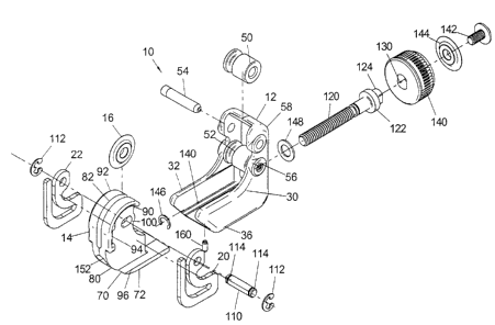
PREFERRED EMBODIMENT
Referring now to the drawings wherein the showings are for the purpose of
illustrating a
preferred embodiment of the invention only and not for the purpose of limiting
same, FIGURES 1-5
show tube cutter 10 having a first frame, or housing, 12 and a second frame,
or cutter head, 14 on
which is rotatably mounted cutter wheel 16 for cutting tube T, as best shown
in FIGURES 4 and 5.
During the cutting operation, cutter 10 is assembled onto the tube and
rotated, either manually or by
an electric driving handle. During rotation, a spring element in the form of
two spaced, sheet metal
springs 20, 22, as illustrated in FIGURE 6, automatically feeds wheel 16 into
the tube. In operation,
the second frame is slidably moved with respect to the first frame until
cutter wheel 16 engages tube
T. Thereafter, further movement of the second frame deforms springs 20, 22
until the springs are
8
CA 02331307 2001-O1-18
fully collapsed. The spring provides the cutting force between the cutter
wheel 16 and tube T as tool
is rotated about the tube. ,
Housing 12 is the first frame which is relatively fixed in the preferred
embodiment and
includes spaced walls 30, 32 joined at a base 36 containing transverse slide
grooves 40 extending
5 in the direction perpendicular to the axes of rollers 50, 52. These support
rollers are rotatably
mounted on shafts 54, 56 supported in spaced walls 30, 32. Grooves 40 are
perpendicular to the
plane of the axes of rollers 50, 52 positioned in recess 58 of housing 12. The
rollers define cradle
C for receiving tube T to be cut by tool 10. This cradle, in some low cost
cutters, is defined by two
angled support surfaces, even though rollers are preferred. For purposes to be
explained later,
10 between base 36 and rollers 50, 52 is a support bore 60 machined in boss 62
provided above base
36. The second frame or cutter head 14 includes a lower base 70 with outwardly
extending runners
or ways 72 slidably received in grooves 40 of the base 36. In this manner,
cutter head 14 slides
toward and away from housing 12 in the direction designated by arrow 70a in
FIGURE 3.
Upstanding arm 80 has a bifurcated top defining a slot 82 to receive cutter
wheel 16. Outwardly
facing generally curved ribs 90, 92 terminate in lower vertically oriented
spring abutments 94 that
are generally perpendicular to a lower spring ledge or rest 96. Springs 20, 22
rest on ledge 96 with
the rearward portion of the springs fixed against abutment 94. The upper
bifurcated portions of arm
80 each include an elongated opening 100 for receiving shaft 110 that mounts
cutter wheel 16 on arm
80. Shaft 110 extends through openings 100 and through the center of cutter
wheel 16. It is held
on the upstanding arm 80 by two snap rings 112 coacting with grooves 114 on
the opposite ends of
the shaft. Arm 80 includes the rotatable and movable structure for cutter
wheel 16.
9
CA 02331307 2001-O1-18
In accordance with the invention, cutter head 14 is slidable toward and away
from the tube -
cradle C on housing 12 by spaced groove 40 in the housing and outboard runners
or ways 72 on base
70 of the second frame or cutter head 14. To accomplish this positive sliding
action, a threaded
shaft 120 is captured in housing 12 by bore 60 using snap ring 146. Although
the threaded shaft
mechanism for sliding the two frames with respect to each other could take a
variety of mechanical
configurations, in the preferred embodiment, threaded shaft 120 is a bolt
having an upset head 122
with a shaped crown 124 that fits in shaped hole 130 of knob 140. Flat
surfaces on the crown and
in the shaped hole allow the knob to rotate bolt 122. Smooth headed bolt 142
captures washer 144
when it is threadably mounted into threaded bore 145, best shown in FIGURE 3.
Thus, knob 140
is captured between washer 144 and head 122 of bolt 120. To hold the knob
assembly against axial
movement with respect to frame 12, bolt 120 is fixed rotatably in bore 60 by
snap ring 146 on one
side and low friction washer 148 on the opposite side. In this manner, knob
140 rotates bolt 120
freely in bore 60 in which the bolt is axially fixed. Cutter head 14 includes
threaded bore 150
terminating in an outward clearance countersink 152. Rotation of knob 140 in
one direction
separates frames 12, 14. Rotation in the opposite direction brings frame or
head 14 toward frame
or housing 12. This linear movement is a smooth positive driving action
controlled directly by the
knob 140 to allow relative sliding of the two frames in the direction of arrow
70a shown in FIGURE
3. To prevent separation of the frames, a removable pin 160 extends into
linear slot 162 at base 70.
The slot terminates at abutment 164. Consequently, pin 160 in base 36 and stop
164 in base 70 limit
the retracted position of the frames 12, 14.
For cutting the tube, the tube T is received in cradle C with its central axis
a, shown in
CA 02331307 2001-O1-18
FIGURE 4, parallel to the axes of rollers 50, 52. Rotation of knob 140 moves
cutter wheel 16 into .
engagement with the tube. Then, the knob is continued to be moved until the
wheel 16 is forced
back with springs 20, 22 collapsed against abutments 94 on opposite sides of
upstanding arm 80.
This loads the cutter wheel for the cutting action. Tool 10 is then rotated
either manually or by a
S power drive mechanism to cut the tube with wheel 16. The initial position of
the wheel is shown
in FIGURE 4 and the cut completed position is shown in FIGURE 5. The
difference in these
positions is the location of shaft 110 in openings 100 as shown in FIGURES 7A,
7B. The loaded
condition of FIGURE 4 and the cut position of FIGURE S have a space difference
b, shown in
FIGURE 6. With the two springs fully collapsed, the force for cutting is at
its maximum. Of course,
a lesser force could be used for cutting the tube by only partially collapsing
springs 20, 22.
Details of spring 20 are shown in FIGURE 6. This same description applies to
the opposite
spring 22. Upstanding legs 200, 202 are terminal ends of a flat sheet metal
spring. These legs are
spaced apart a distance b at rest, and are touching when fully loaded. Leg 200
includes a vertical
section 202a merging into a lower run 200b. Leg 202 has an upper head 202a
with a shaft receiving
hole 202b and a downwardly extending connecting section 202c. Vertical
connector portion 210
forms a bight by joining legs 200, 202. Run 200b and section 202c define
horizontal slot 212 having
a general length c. This length of slot 212 is selected to generate the
desired force when leg 202 is
forced against leg 200. The spring steel material of the spring, the length c
of the slot, and the shape
of the spring are selected to provide the desired force on cutter wheel 16
when the two upstanding
spring legs are in the abutting relationship shown in FIGURE 4. This position
is also shown by the
dashed line in FIGURE 6. In practice, the applied force is selected to be in
the general neighborhood
11
CA 02331307 2003-08-11
of 80-150 pounds when combining the forces of both springs 20, 22. This is the
cutting force -
exerted against tube T. Opening 100 in each of the bifurcated sections of arm
80 receives shaft 110.
This shaft moves from the position shown in FIGURE 7A to the position shown in
FIGURE 7B
when the springs are shifted from the solid line position to the dashed line
position, as shown in
S FIGURE 6. In practice, the length of openings 100 is greater than the actual
travel of shaft 110
during the loading and cutting action. These openings merely guide the cutter
wheel and assure that
it remains in the proper orientation during the cut action. The available
stroke of cutter wheel 16 is
distance b.
The invention involves positively sliding the second frame toward the first
frame by a
positive thread driving action or other positive drive mechanism. When the
cutter wheel contacts
the tube there is fiuther linear sliding movement of the second frame toward
the first frame. This is
completely different from a concept wherein there is an intermedial spring
action in the linear
moving mechanism. In such prior arrangements, the actual cutting action
involves further metal-to-
metal sliding of the two frames. This action is not used in the present
invention. Another
embodiment for accomplishing this objective is schematically illustrated in
FIGURES 8 and 9.
Cutter 300 has a first frame 302 and a second frame 304 for rotatably
supporting a cutter wheel 310
on a bifurcated end 312 of upstanding arm 314 through use of shaft 316 through
bifurcated end 312.
Frame 302 includes the normal support rollers 320, 322 extending in the
direction parallel to the tube
to be cut. Another linear motion mechanism based upon a threaded drive is
illustrated. Lower base
section 330 is an integral part of frame 304. It is slidably received in base
340 of frame 302. To
prevent rotation of base section 330 with respect to frame 302, there is
provided outwardly facing
12
CA 02331307 2004-02-04
ribs 332, 334 slidably received in grooves 342, 344 in base 302a of housing or
frame 302. Threaded
bore 350 in section 330 receives a threaded shaft 360 rotatably supported by
shank 362 and held axially
with respect to base 302a by snap ring 364 in circumferentially extending
grove 366. The outward end
of shank 362 is knob 370. As so far described, cutting tool 300 operates in
the same manner as cutting
S tool 10. To provide the spring action, section 400 of arm 310 has a reduced
width d. This portion is
flexible in a direction perpendicular to the axes of rollers 320, 322. Thus,
knob 370 brings cutter wheel
16 into engagement with the tube to be cut. Section 400 is then flexed
backwardly by continued rotation
of knob 370. To limit the backward flexing of section 400, an optional stop
plate 402 is bolted to
section 330 by bolt 404. This provides a gap a to control the amount of
deflection as wheel 16 is moved
into the loaded cutting position. The use of a frame that flexes for the
purposes of advancing a cutting
tool is shown in Dubinsky U.S. Patent No. 5,345,682 issued September 13, 1984.
This patent provides
background information on the feature of a flexible frame to advance the
cutter.
Various structures can be used for practicing the invention. The two
embodiments are merely
illustrative. They illustrate the invention as will be practiced, and an
alternative embodiment of the
invention.
13