Note: Descriptions are shown in the official language in which they were submitted.
CA 02331317 2000-11-06
WO 99/57473 PCT/US99/Ob5b5
MULTI-LAYER FILLER PIPE FOR VEHICLE FUEL TANKS
This patent application is related to U.S. Provisional Application Serial No.
601084,568, which was filed May 7, 1998, the entire disclosure of which is
incorporated herein by reference.
FIELD OF THE INVENTION
The present invention relates to a pipe for use in a motor vehicle, more
specifically, to a multi-layer filler pipe for connection to a motor vehicle
fuel tank.
BACKGROUND OF THE INVENTION
Filler pipes for connection to motor vehicle fuel tanks are subject to
multiplE:
design constraints, including those related to emissions tolerance,
conductivity,
price, weight, and durability. For example, the U.S. Clean Air Act Amendment
of
1990 sets more stringent hydrocarbon emissions standards for all vehicles. So
called light vehicles will be required to meet a diurnal standard of no more
than 2
grams of emitted hydrocarbons per day. The diurnal standard will be phased in
over
the next few years, ending in the year 2000 with '100% compliance.
Regarding conductivity, motor vehicle fuel possesses charged particles that
can build up as the fuel moves across a non-conductive surface. When this
charge
is released in a localized area of a filler pipe, the discharge can degrade
the strength
of the pipe and lead to pipe failure, leaks, and fires. Thus, the surface over
which
fuel passes in a filler pipe should have sufficient surface conductivity to
dissipate any
electrostatic charge that may build up.
Price constraints also define several design parameters. While fabrication
costs are primary considerations, operation costs of the resulting vehicle are
also
closely monitored. These operation costs are functions of the vehicle's
weight,
which affects fuel consumption and efficiency. To address these concerns it is
important to identify a low cost, lightweight material from which to construct
a filler
pipe.
Fire is a constant threat in an automotive environment. A filler pipe should
be
resistant to this threat. Additionally, recent changes in European
specifications have
SUBSTITUTE SHEET (RULE 26)
CA 02331317 2000-11-06
WO 99/57473 PCT/US99/0~565
-2-
increased the fire resistance requirements for automobiles and their fuel
systems in
the European market. For these reasons it is important that the filler pipe be
sufficiently resistant to fire.
A filler pipe must also withstand the hazards of a motor vehicle environment,
including corrosion and mechanical failure. Corrosive agents to which the pipe
may
be exposed include fuel, oil, brake fluid, and road salt. Mechanical phenomena
that
may act upon a filler pipe include deformation, fatigue, and vibration. For
these
reasons, it is important that the filler pipe material be sufficiently
durable.
In both Europe and the United States, new fuel systems are being considered
to achieve these design criteria. In the United States, most vehicles utilize
steel filler
pipes. While steel pipes are relatively easy to manufacture, have good
conductive
properties, and are impermeable to hydrocarbons, they are undesirably heavy
and
subject to corrosion. In Europe, many vehicles are equipped with polymer-based
filler pipes made of high density polyethylene. These pipes are low-cost and
lightweight, but they have high permeation and most of them are non-
conductive.
Thus, European filler pipe technology possesses a significant disadvantage of
failiing
to meet U.S. emissions requirements in a non-conductive embodiment.
Fuel lines and vapor return tines of synthetic materials have been proposed.
These lines possess some of the characteristics that are desirable in a modern
filler
pipe. However, the materials they are made out of, such as polyamides, are
prohibitively expensive for use in filler pipe construction. These cost
constraints are
tolerated in fuel line construction due to additional design criteria that are
not shar~sd
with filler pipes, such as high temperature and high pressure performance and
reduced elongation characteristics.
Various synthetic tubing materials have been suggested in the area of fuel
line construction. WO 98/01694 to Hsich discloses a multi-layer tubing
assembly for
use in fuel line applications. An outer layer of a rubber-like multiphase
polymer, e.g.
polyamide, surrounds an intermediate adhesive layer and an inner layer of a
semi~-
conductive fluoroplastic. The rubber-like multiphase polymer of the outer
layer is
selected from the group consisting of polymer blends or copolymers of
polyamide~;,
polyesters, polyurethane, and matallocene polyolefins.
SUBSTITUTE SHEET (RULE 26)
CA 02331317 2000-11-06
WO 99/57473 PCT/US99/OIi565
-3-
U.S. Patent No. 5,566,720 to Cheney proposes a two-layer fuel line
composed of a thick corrosion-resistant outermost layer formed of a material,
preferably a polyamide, that is durable and resistant to environmental
degradation.
An innermost fuel-contacting layer of a terpolymer is bonded to the thick
outer layer.
U.S. Patent No. 5,678,611 to Noone discloses a three-layer, co-extruded fuel
line composed of an outer exterior wail of an extrudable polyamide, an inner
hydrocarbon barrier layer, and an intermediate bonding layer. The inner
hydrocarbon barrier layer may be capable of dissipating electrostatic energy,
whilE~
the outer layer comprises a relatively thick layer of polyamide that is non-
reactive
with the external environment.
It would be desirable to have a filler pipe that is highly impermeable to
hydrocarbons and capable of discharging static electricity. Furthermore, the
desired
filler pipe would be resistant to fire and damage by fire. Finally, it would
be desirable
that this filler pipe be lightweight, inexpensive and resistant to chemical
and
mechanical degradation due to conditions in a motor vehicle environment.
SUMMARY OF THE INVENTION
It is an object of the present invention to provide a highly impermeable,
conductive, fire resistant, lightweight, inexpensive and sturdy filler pipe.
Polyethylene, especially medium to high density polyethylene, is a durable
material
that is an inexpensive alternative to other durable synthetic materials, such
as
polyamides. A filler pipe made of polyethylene can be made with thicker walls
due to
polyethylene's lower cost and lighter weight. The added thickness and choice
of
material improve the filler pipe's resistance to fire while improving
durability. A filler
pipe constructed of an outer zone of polyethylene and a zone of a conductive
barrier
material is advantageously impermeable, conductive, fire resistant,
lightweight,
inexpensive, and resistant to chemical and mechanical degradation, thereby
addressing the above-mentioned concerns and shortcomings of conventional
filler
pipe technology.
In accordance with the present invention, the filler pipe comprises, in cross
section, two zones that directly abut each other, wherein an outer zone
comprises
SUBSTITUTE SHEET (RULE 26)
CA 02331317 2000-11-06
WO 99/57473 PCT/US99/01i565
-4-
polyethylene and an inner zone comprises a material or materials capable of
dissipating electrostatic energy and blocking the permeation of hydrocarbons.
The above objects and advantages can be realized and attained by means of
the instrumentalities and combinations particularly pointed out in the
appended
claims. Additional objects and attendant advantages of the present invention
will be
set forth, in part, in the description that follows, or can be learned from
practicing or
using the present invention. It is to be understood that the foregoing general
description and the following detailed description are exemplary and
explanatory
only and are not to be viewed as being restrictive of the invention, as
claimed.
BRIEF DESCRIPTION OF THE DRAWING
The accompanying drawings which are incorporated in, and constitute a part
of, the specification, illustrate embodiments of the present invention and,
together
with the description, serve to explain the principles of the present
invention.
Figure 1 is a sectional view through a wall of a piece of the pipe of an
embodiment of the present invention;
Figure 2 is a sectional view through a wall of a piece of the pipe of another
embodiment of the present invention;
Figure 3 is a sectional view through a wall of a piece of the pipe of another
embodiment of the present invention;
Figure 4 is a sectional view through a wall of a piece of the pipe of a
further'
embodiment of the present invention;
Figure 5 is a sectional view through a wall of a piece of the pipe of still
another
embodiment of the present invention;
Figure 6 is a sectional view through a wall of a piece of the pipe of yet
another
embodiment of the present invention;
Figure 7 is a sectional view through a wall of a piece of the pipe of the
embodiment of Figure 6, with greater detail of the adhesive layer (14) of the
inner
zone (2).
SUBSTITUTE SHEET (RULE 26)
CA 02331317 2000-11-06
WO 99/57473 PCT/US99/OIi565
-5-
DETAILED DESCRIPTION OF PREFERRED EMBODIMENTS
All patents, patent applications and literatures cited in this description are
incorporated herein by reference in their entirety. In the case of
inconsistencies, the
present disclosure, including definitions, will prevail.
The present invention is a multi-layer filler pipe for connection to a motor
vehicle fuel tank. The filler pipe is capable of transporting fluids,
particularly those:
containing hydrocarbons. The filler pipe material is suitable for use in motor
vehicles
and comprises an outer zone that is resistant to the environment of a motor
vehicle
by being capable of withstanding impact from stones and road debris, various
shocks, vibrational fatigue, and changes in temperature. Furthermore, the
filler pipe
material is able to withstand exposure to various corrosive or degradative
agents to
which it will be exposed through the normal course of operation of the motor
vehicle,
such as brake fluid, engine oil, road salt, gasoline, and the like.
The filler pipe of the present invention comprises an outer zone and an inner
zone. The filler pipe of the present invention can be fabricated by any
suitable
means, such as blow molding, co-extrusion, and the like. Co-extruding the
given
thermoplastic materials in a conventional co-extrusion process to form the
outer and
inner zones, however, is most preferred. The filler pipe can either be co-
extruded to
a suitable length or can be co-extruded in continuous length and subsequently
cut to
fit a given application. The various layers of the filler pipe construction
are preferably
bonded to one another and are preferably resistant to separation throughout
the
lifetime of the filler pipe.
The filler pipe of the present invention can have any suitable wall thickness
desired, as measured from the innermost wall of the inner zone to the
outermost wall
of the outer zone. The preferred wall thickness of the present invention, for
use in
automotive systems, will generally be between about 1.5 mm and about 3.0 mm,
preferably about 2.0 mm to about 3.0 mm, most preferably, about 2.4 mm to
about
2.6 mrn.
The outer zone (1 ) has a wall thickness sufficient to provide suitable
strength
and endurance to the multi-layer pipe of the present invention. "Outer zone"
means
that zone which is positioned radially outermost of the filler pipe. The outer
zone (1 )
SUBSTiME SHEET (RULE 26)
CA 02331317 2000-11-06
WO 99/57473 PCT/US99/Ob565
-6-
comprises a single layer of polyethylene that provides shape to the resulting
filler
pipe. The outer zone (1 ) polyethylene can also be made thick enough to
provide
adequate structure for mounting components to the filler pipe. It is resistant
to fire,
impact, vibrational shock, and the corrosive effects of a typical motor
vehicle
environment.
The polyethylene used in the filler pipe of the present invention can be of
any
suitable grade, however, medium to high density polyethylene are preferred.
The
poiyethylenes used in filler pipes can be medium or high density, depending on
the
process and desired end characteristics of the filler pipe. If the filler pipe
is made
using a blow molding process, then low melt index high density polyethylene is
often
preferred. Similarly, if the filler pipe layers are formed via co-extrusion,
then either
medium density polyethylene or high density polyethylene is often preferred.
Environmental stress crack resistance is often considered an important design
characteristic. If this is the case, then one should choose a grade of
polyethylenE:
with good environmental stress crack resistance properties. Other factors
considered when choosing a polyethylene include the flex modulus and other
mechanical properties. Examples of grades of polyethylene that may be used
include, without limitation, the commercially available polyethylenes known as
Sollvay
Fortiflex~ G36-24-149, K44-24-123, and K44-08-123.
The inner zone (2) is positioned radially innermost of the filler pipe. The
inner
zone (2) contains a material capable of serving as a hydrocarbon barrier layer
to
prevent significant permeation of the components of gasoline through to the
outer
zone (1 ) of the filler pipe and thus out to the surrounding environment.
Suitable
materials include, but are not limited to, chlorotrifluoroethylene/ethylene
copolymer,
polychlorotrifluoroethylene,
tetrafluoroethylene/hexafluoropropylene/vinylidene
fluoride terpolymer, tetrafluoroethylene/ethylene copolymer, and
polyvinylidene
fluoride.
The inner zone (2) has an innermost material with a surface oriented to come
into direct contact with fuel traveling through the ~Iler pipe. The selected
material is
suitably resistant to the corrosive effects of fuel. Examples of materials
that can be
SUBSTa<TUTE SHEET (RULE 2B)
CA 02331317 2000-11-06
WO 99/57473 PCT/US99/Ofi565
used for the inner surface include, but are not limited to, high density
polyethylene,
chlorotrifluoroethylene/ethylene copolymer, poiychlorotrifluoroethylene,
tetrafluoroethylene/hexafluoropropylene/vinylidene fluoride terpoiymer,
tetrafluoroethylene/ethylene copolymer, and polyvinylidene fluoride.
Importantly, the selected innermost material in the inner zone (2) is capable
of
dissipating electrostatic energy. The material of the innermost layer of the
inner
zone (2) can include conductive material incorporated therein. The conductive
material can be any suitable material of a composition and shape capable of
electrostatic dissipation. Examples of conductive material that can be used
include,
without limitation, elemental carbon, stainless steel, silvered glass fibers,
metalized
textiles, and highly conductive metals such as iron, copper, silver, gold,
nickel, silicon
and mixtures thereof. The conductive metals can be present in the form of
granules,
flakes, fibers, and the like. The term "elemental carbon", as used herein,
refers to
materials commonly referred to as "carbon black"'. Preferably, the conductive
material is co-extruded with the barrier materials employed in the inner zone
(2) in
sufficient quantity to permit electrostatic dissipation with resistivity less
than, for
example, about 106 ohm/sq.
I of the
innermost la of the inner zone (2) is generally limited by considerations of
low
temperature durab ' and resistance to the degradative effects of the gasoline
or
fuel passing through the r pipe. More specifically, the addition of conductive
material can make the polymer sceptible to the permeation of hydrocarbons. If
lit
is necessary to have a selected poly with high conductivity such that the
conductive polymer of the inner zone {2) is insufficient barrier to
hydrocarbons,
then there shall be a second layer in the inner zo 2) which comprises a
polymer
selected from the group of chlorotrifluoroethylene/ethyle copolymer,
polychlorotrifluoroethylene, tetrafluoroethylene/hexafluoroprop ne/vinylidene
fluoride terpolymer, tetrafluoroethylene/ethylene copolymer, and pol ylidene
fluoride that does not contain added conductive material.
If an adhesive layer is used, the adhesive should be chosen such that th
SUBSTITUTE SHEET (RULE 2B)
~
'~ ~~~ ~J. ~L ,~.. ~ IU v J 1 i ~ 'f U A1V~ ,S~i ~.. :.~ r :v ~ i; ~; T ~'rl :
.. .. i. ~Y~i ~' ~ ': S Y '" _ :.
PCT~s ~cj~6 565
The amount of conductive material incorporated in the selected material of
th.e
innermost layer of the inner zone (2) is generally limited by considerations
of low
temperature durability and resistance to the degradative effects of the
gasoline or fuel
passing through the filler pipe. More specifically, the addition of conductive
material can
make the polymer susceptible to the permeation of hydrocarbons. If it is
necessary t~~
have a selec~ed polymer with high conductivity such that the conductive
pol5~rner of the
inner zone (2) is an insufficient barrier to hydmcarbons, then there shall be
a second layer
in the inner zone (2) which comprises a polymer selected from the group of
' chlorotrifluoroethylene/ethylene copolymer, polychlorotrifluoroethylene,
tetrafluoroethylene/hexafluoropropylenelvinylidene fluoride terpolymer,
tevafluoroethylene/ethylene copolymer, and polyvinylidene fluoride that does
not contain
added conductive material.
If an adhesive layer is used, the adhesive' should be chosen such that there
is
sufficient laminar adhesion between the adhesive and the two abutting layers
that there
will not be separation of the layers during the lifetime of the pipe. The
adhesive should be
compatible with polyethylene and the barrier layer. If a single adhesive is
not compatible
with both, then two different adhesive layers can be used: one compatible with
polyethylene and the other compatible with the barrier layer. making sure that
there ;is
sufficient bonding between the two adhesives. It may° also be desirable
to use a mixture
of two or more types of adhesives. It is known to use pressure sensitive
adhesives, hot
melt adhesives, and adhesive with cross-linkers when working with
polyethylene. Such
adhesives can be reactive or non-reactive, providing chemical or mechanical
bonding.
Examples of adhesives that possess such properties include, without
limitation, ADrriER~'
(Mitsui Petrochemicals Industries) which is based on a polyethylene and
malefic
anhydride, BLEMMER~ (Nippon Oils & Fats C:o.) which is based on a methyl
methacrylate/glycidyl methacrylate copolymer and mixtures thereof.
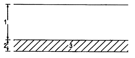
Figure 1 depicts a preferred embodiment of the filler pipe of the present
invention
wherein the outer zone (1) is comprised of a single layer of polyethylene and
the inr.~er
zone (2) is comprised of a single conductive layer (3) of the barrier material
selected from;
the group consisting of conductive chlorotrifluoroethylene/ethylene copolymer,
conductive polychlorotrifluoroethylene. and conductive
tetrafluoroethylenelethylene
CA 02331317 2000-11-06 ~ ~rt~yJ-~-.,~ ~~
-_ -i _
CA 02331317 2000-11-06
WO 99/57473 PCT/US99/OEi565
_g_
~ritt rtot--be sep~fiatier~-flf the--Dyers-~t~rtng-t#e-+ifeti~e#-t#e--p+pe:-
Tie-adhes+ve
sh Id be compatible with polyethylene and the barrier layer. If a single
adhesive is
not co patible with both, then two different adhesive layers can be used: one
compatib with polyethylene and the other compatible with the barrier layer,
making
sure that the is sufficient bonding between the two adhesives. It may also be
desirable to use mixture of two or more types of adhesives. It is known to use
pressure sensitive hesives, hot melt adhesives, and adhesive with cross-
linkers.
when working with pol thyfene. Such adhesives can be reactive or non-reactive,
providing chemical or mectyanical bonding. Examples of adhesives that possess
such properties include, with\o t limitation, Mitsui (America) AdmerTM
adhesive,
BlemmerTM adhesive and mixture thereof.
Figure 1 depicts a preferred a bodiment of the filler pipe of the present
invention wherein the outer zone (1 ) is ~mprised of a single layer of
polyethylene
and the inner zone (2) is comprised of a s'i~rl~le canductive layer (3) of the
barrier
material selected from the group consisting of~,,onductive
~yterfiefetlfiylene-eopolyn~ier~ There is sufficient laminar
adhesion between the outer zone (1 ) layer and the inner zone (2) layer (3) to
provide
the desired level of laminar bonding.
Figure 2 shows another preferred embodiment of the filler pipe of the present
invention wherein the outer zone (1 ) is comprised of a single layer of
polyethylene.
The inner zone (2) is comprised of an outermost layer (4) of an adhesive and
an
innermost layer (5) of a conductive form of a barrier material selected from
the group
consisting of conductive chlorotrifluoroethylene/ethylene copolymer,
conductive
polychlorotrifluoroethylene, conductive tetrafluoroethylene/
hexafluoropropylene/vinylidene fluoride terpolymer, and conductive
tetrafluoroethylene/ethylene copolymer. The adhesive layer (4) is capable of
bonding to both the outer zone (1 ) layer and the innermost layer (5) of the
inner zone
(2) .
SUBSTITUTE SHEET (RULE 26)
CA 02331317 2000-11-06
WO 99/57473 PCT/US99/Ob~565
-9-
Figure 3 shows a preferred embodiment of the filler pipe of the present
invention wherein the outer zone (1 ) is comprised of a single layer of
polyethylene.
The inner zone (2) is comprised of an innermost layer (7) of a conductive form
of a
barrier material selected from the group consisting of conductive
chlorotrifluoroethylene/ethylene copolymer, conductive
polychlorotrifluoroethylenE~,
and conductive tetrafluoroethylene/ethyiene copolymer, and an outermost layer
(i3)
of a non-conductive form of the same barrier material selected from the group
consisting of chlorotrifluoroethylene/ethylene copolymer,
polychlorotrifluoroethylene,
and tetrafluoroethylene/ethylene copolymer. There is sufficient laminar
adhesion
between the outer zone (1 ) layer and the inner zone (2) outermost layer (6)
to
provide the desired level of laminar bonding. There is sufficient homogeneity
between the conductive and the non-conductive forms of the selected barrier
material to provide the desired level of laminar bonding between the innermost
layer
(7) and the outermost layer (6) of the inner zone.
Figure 4 shows a preferred embodiment of the filler pipe of the present
invention wherein the outer zone (1 ) is comprised of a single layer of
polyethylenf:.
The inner zone (2) is comprised of an innermost layer (9) of conductive
polyethylE~ne
and an outermost layer (8) of a barrier material selected from the group
consisting of
chlorotrifluoroethylene/ethylene copolymer, polychlorotrifluoroethylene, and
tetrafluoroethylene/ethylene copolymer. There is sufficient laminar adhesion
between the outer zone (1 ) layer and the inner zone (2) outermost layer (8)
and
between the inner zone (2) innermost layer (9) and the inner zone (2)
outermost
layer (8) to provide the desired level of laminar bonding.
Figure 5 shows a preferred embodiment of the-fttter-pipe of-the-present
invention where~in~e outer zone (1 ) is comprised of a single layer of
polyethylene.
The inner zone (2) is com'~HSgd of an innermost layer (13) of polyethylene, an
intermediate layer (11 ) of a barrier rial selected from the group consisting
of
chlorotrifluoroethylene/ethylene copolymer, ~plorotrifluoroethylene, and
tetrafiuoroethylene/ethyiene copolymer, and two adhesi ayers (10 and 12). The
outermost adhesive layer (10) is capable of bonding to both the~ocrte.~zone (1
) layer
aid-tt~etttrter-zone (2) outermost-layer ($)-to-provide~+~e des+red level of-
laii~inaf
SUBSTfTUTE SHEET (RULE 26)
~UG, c9. ?OGC 11:41~,M MCC~~r,M~~'~ ~wl~~ EM~~~ :ACC
~(~'~°;i~ ~ ~ w , , ,-~ y., c-
. , .; _ . ~ ,.; a 6 '~
-_ ?
-9- . .- -~ ,, f'f.
Figure 5 shows a preferred embodiment of the filler pipe of the present
invention
wherein the outer zone (1) is comprised of a single layer of polyethylene. The
inner 2:one
' (2) is comprised of an innermost layer (13) of polyethylene, an intermediate
layer (11) of
a barrier material selected from the group consisting of
chlorotrifluoroethylene%ethylene
S ; copolymer, polychlorotrifluoroethylene, and tetrafluoroethylene/ethylene
copolymer, and
two adhesive layers (10 and 12). The outermost adhesive Iayer (10) is capable
of bonding
to both the outer zone (1) layer and the inner zone (2) outermost layer (8) to
provide the
desired level of laminar bonding. The innermost adhesive layer (12) is capable
of bonding
to both the inner zone (2) innermost layer (13) and the inner zone (2)
intermediate layer
10; (11) to provide the desired level of laminar bonding.
Figure 6 shows a p.eferted embodiment of the filler pipe of the present
invention
wherein the outer zone (1) is comprised of a single layer of polyethylene. The
inner 2:one
(2} is comprised of an outermost layer (14) of an adhesive. an innermost layer
(16) of the
s conductive form of a barrier material selected from the group wnsisting of
conductive
15, chlorotrifluoroethylenelethylene copolymer, conductive
polychlorotrifluoroethylene,
conductive tetrafluoroethylenelethylene copolymer. and conductive
tetrafluoroethylene/hexafluoropropylene/vinylidene fluoride terpolymer, and an
intermediate layer (15) of the non-conductive form of the same barrier
matezial selected
from the group consisting of chlorotrifluoroethylenelethylene copolymer,
20 polychlorotrifluoroethylene, tetrafluoroethylenelethylene copolymer, and
tetrafluoroethylenelhexafluoropropylene/vinylidene fluoride terpolymer. The
adhesive
layer (14) is capable of bonding to both outer zone ( 1 ) layer and the inner
zone (2)
intermediate layer (15) to provide the desired level of laminar bonding. There
is
sufficient homogeneity between the conductive form of the barrier material and
its non-
25 conductive form to provide the desired level of laminar bonding between the
innermost
layer ( 16) and the intermediate layer ( I S) of the inner zone (2).
In a preferred embodiment of Figure 6, the outer zone (1) is comprised of a
single
layer of polyethylene. The inner zone (2) is comprised of an innermost layer
(16) of
conductive polyvinylidene fluoride, an intermediate layer (15) of non-
conductive
30 polyvinylidene fluoride, and an outermost layer (14) of an adhesive, The
adhesive is
capable of bonding the outer zone (1) to the non-conductive layer (15) of
polyvlnylidene
fluoride and can be selected, without limitation, from the group consisting of
ADMER~
CA 02331317 2000-11-06
3 L~:,; .~ , .
nUh. 2'~. LI~IJU 11.~1n~Y''. ~F.;L':,.",~J;~~'~ ;~! ~ C~s~"_f:~N1,. .'~~C .. C
PCTfUS ~~':' n~,, 5~5
-10- ; _.
= ~ ~~00
adhesive, BLEMMER'~ adhesive and mia-tures thereof. In a preferred embodiment
shown
in Figure 6, the adhesive layer (14) is a mixture of ADMER~ and BLEMMER~
adhesive.
Alternatively, in a preferred embodiment shown in Figure 7. the adhesive layer
( 14)
comprises an outermost sublayer of ADMER~ adhesive (17) and an innermost
sublayer
5, of BLEMMER~ adhesive (18). There is sufficient homogeneity between the
conductive
polyvinylidene fluoride and the non-conductive polyvinylidene fluoride to
provide the
desired level of laminar bonding between the innermost layer (16) and the
intermediate
layer (15) of the inner zone.
The foregoing description of the preferred embodiments of the present
invention
10: has been presented for purposes of illustration and description. It is not
intended to be
exhaustive or to limit the invention to the precise form disclosed. Obviously,
many
modifications and variations will be apparent to practitioners skilled in this
art. Similarly,
any process steps described might be interchangeable with other steps in order
to achieve
the same result. The embodiment was chosen and described to best explain the
principles
15 of the invention and its best mode practical application to thereby enable
others skilled in
the art to understand the invention for various embodiments and with various
modifications as are suited to the particular use contemplated. It is intended
that the
scope of the invention be defined by the claims appended hereto and their
equivalent:>.
Those skilled in the art will recognize, or be able to ascertain using no more
than routine
20 experimentation. many equivalents to the specific embodiments of the
invention
specifically described herein.
CA 02331317 2000-11-06
,_.