Note: Descriptions are shown in the official language in which they were submitted.
CA 02331366 2000-11-03
WO 99/57006 PCT/IT99/00101
HULL FOR SHIPPING WITH A MONO-THREE-CATAMARAN
ARCHITECTURE
This invention relates to a hull for shipping with a mono-three-
s catamaran architecture.
The total resistance to forward motion of a boat is basically the
sum of the skin friction (that is obtained by integrating the tangential
stress over all the hull surface in the direction of the motion), the
viscous drag (that is connected to the energy dissipated owing to the
Io viscous effects) and the residua/ resistance. The residual resistance
includes to a great extent the wave resistance, that is connected to
the energy dissipated by the hull in making gravitational waves.
A hull moving forward generates a global wave formation, that is
constituted in turn by two distinct but interacting wave systems: a
1s diverging wave system and a transverse wave system. The global
wave formation is contained inside two lines, that are called boundary
lines of the diverging wave system. Each boundary line forms an angle
of 19.5 degrees with the longitudinal symmetry plane of the hull. The
crest lines of the transverse waves are perpendicular to the direction
20 of the hull motion near the hull and turn backward as the transverse
waves approach the diverging waves until they join the same diverging
wave system. In front of the bow of the ship there is a high pressure
area that generates a prominent wave front as a part of the transverse
and diverging wave system. Further wave systems form near the bow
Zs and stern sides of the hull.
CA 02331366 2000-11-03
WO 99/57006 PCT/IT99/00101
A resulting wave system may be often considered as formed by
four wave systems:
~ a bow wave system owing to the high pressure area that forms
near the bow during the forward motion of the hull;
s ~ a wave system foreward from the bow side portion owing to a
low pressure area that forms near such a side portion;
~ a wave system that forms along the stern side portion owing to a
low pressure area existing in such a part of hull;
~ a stern wave system owing to a high pressure area that forms in
1o the stern area.
It is very difficult to foresee the exact position of the crest of
both the bow wave and stern systems. It is likewise difficult to foresee
the position of the troughs of the wave systems formed in the bow
and stern side portions of the hull owing to high pressure peaks that
is are generated near said bow and stern side portions.
Said four wave systems that form the global wave system can
interfere with each other in a more or less favorable manner for the
resistance to forward motion of the hull. However, since the wave
resistance contributes to the total resistance to a great extent, one
Zo should act just on the wave resistance by taking measures intended
to reduce said wave resistance so that the propulsive power installed
on a boat may be decreased, with the speed reached by the boat
being the same.
In the last years the designers have had as a goal to reduce as
is much as possible the wave formation generated by the hull moving
-2-
CA 02331366 2000-11-03
WO 99/57006 PCT/IT99/00101
forward.
On the other hand there are designs that improve the conditions
of resistance to forward motion by utilizing the bow wave formations,
holding in the same in the bottom of the hull and creating a more
s prominent resulting stern wave system. Among the others U.S. Patent
No. 5,402,743 issued on Apr. 4, 1995 to Holderman entitled "Deep
chine hull design" discloses a hull with a bottom structure forming two
longitudinal channels which extend fore and aft along all the hull. In
the above Patent, the bow wave, being assisted in its rotatory motion
1o and controlled in a certain measure, deviates into these channels. The
bow wave is controlled through the conformation of said channels
according to a Venturi tube. The inventor of the above Patent makes it
a condition, among the other things, that air in the bow of the hull is
thrown out before being included inside the same channels. Further
1s this condition sets limits on the shape of the hull that must have curve
sides, i.e. the hull is tapered in its cross sections toward bow and
toward stern and accomplishes a Venturi tube structure along all its
length through a pair of inverted channels that border a continuous
keel fore and aft.
ao This invention is close to the above Patent only in the insight of
diverting under the hull the bow wave formed in the forward motion.
However, differently from the above Patent, an object of this
invention is a hull, in which a portion of the energy spent to form the
bow wave system is used to increase a hydrodynamic sustentation of
2s the hull.
-3-
CA 02331366 2004-05-07
Another object of this invention is a hull in which the energy dissipated
in both friction and viscous phenomena is reduced.
Furthermore, an object of this invention is a hull in which a resulting
stern wave formation and then a dissipation energy connected therewith is
limited.
Yet another object of this invention is a hull having a stability of shape
whereby the hull goes steadily to a balance position whatever it might be the
speed of the shipping and, within limits, the conditions of the sea.
A further object of this invention is a hull having a length less than that
of other hulls of shipping with equal carrying capacity.
For these purposes, the present invention provides a deep chine hull
for shipping with a mono-three-catamaran architecture comprising:
~ a bow point connected to hull sides lying in vertical parallel planes
symmetrically opposed to a center line that end at a stern;
~ a pair of chines disposed laterally to the center line, each chine
defining a lower edge of said hull sides, that begins at a desired
cross section plane near the bow point under a waterline and thereafter
defines a longitudinal line extending continually aftward to said stern;
~ a keel, beginning near the bow point and extending along the center
line on the underside of the hull aftward for a length less than the
distance between the bow point and the midship section;
-4-
CA 02331366 2000-11-03
WO 99/57006 PCT/IT99/00101
~ a bottom extending laterally between said chines, and between
every chine and said keel where the keel is present; a surface of
the bottom having cross section planes at right angles with the
center line forming convex bottom structures bridging a pair of
s inverted longitudinal bottom channels which extend laterally to
said keel; said pair of channels merging aft from said keel with a
single bottom channel having a profile with channel sides which
are increasingly slanted in the stern cross sections and become
parallel to the hull sides in the stern.
to A hull so shaped according to the invention may be called mono-
three-catamaran.
Said bottom inverted structures have waterlines defining a
bottom shaped as a diffuser with increased cross section areas, fore
and aft, of said channel pair and of said single channel, in which the
is kinetic energy of the flow conveyed from bow is transformed into
pressure energy.
Such a hull enables the energy dissipated in both friction and
viscous phenomena to be reduced since air is conveyed under the hull
inside the channels as above, not to create a continuous air layer and
ao then use an over-craft effect, but to include air into water in order to
carry on a boundary foamy layer, It is important to carry on a
boundary foamy layer on the grounds of the following remarks:
i) if a continuous air layer is carried on, an optimal situation from
the point of view of the reduction of the friction would be obtained;
as however, with the exception of a race-boat, the speed of the hull
-s-
CA 02331366 2000-11-03
WO 99/57446 PCT/IT99/00101
would not be high enough to compress the air layer to such an extent
that the aerodynamic lift effect transferred to the hull is large;
ii) if the channel bottom surface is in direct contact with the water,
there would be the best situation from a point of view of the
s hydrodynamic sustentation of a hull, but the worst from a point of
view of the resistance to forward motion of a boat owing to an
increase of the friction and viscous phenomena due to the widening_of
the wet surface;
iii) a foamy layer conciliates the need of decreasing as much as
Io possible the friction resistance and the possibility of exploiting the
hydrodynamic sustentation. Since the foam is constituted in general by
very small spherical chambers containing air or gas (e.g. exhaust gas),
the foam is rigid enough to allow a sufficient hydrodynamic
sustentation to be transmitted with equal speed of the hull, against a
is reduced resistance to forward motion.
The foamy layer may be suitably obtained by conveying the bow
waves, that are generated by both the keel and the chines, into the
channels, and appropriately designing a propelling apparatus relating
to both the choice and the arrangement thereof.
ao From the standpoint of the response of the hull according to the
invention to the wave system generated when it is moving forward,
the hull has a high pressure area in the bow in connection with the
wave crest, a following low pressure area in connection with a wave
trough and a subsequent low pressure area that would be formed aft
2s from the keel beyond the point of maximum draft of the hull bottom.
-6-
CA 02331366 2000-11-03
WO 99/57006 PCT/IT99/00101
When the speed of the hull changes, the buoyancy center resulting
from the pressure distribution above explained can fall fore or aft the
center of gravity of the shipping. However, the longitudinal position of
the hull may change only for a moment, since by changing the draft of
s the bow and the hull sides, the high pressure area and the following
low pressure area would be change as a consequence, resetting
immediately the hydrodynamic balance. The greater or lower draft of
the stern would change the cross sections of the effuser constituted by
the ascending flat bottom aft from the keel, together with the internal
io sides of the chines, and would help to keep this balance. The flat
bottom would function as a constant support for the hull. In
conclusion, the hull according the invention "sails constantly on its
wave", that is contained between its chines in the portion aft from the
keel to the stern and guided in front by the stem and the keel.
Is Further, owing to the variation of pressure along the channels
from the bow to aft of the keel, the water flow of the bow wave is
subjected to a spiral right hand movement in the left channel and to a
spiral left hand movement in the right channel, both helping the
formation of air bubbles and increasing the foamy layer, with a
Zo reduction of the viscous friction.
One or two propulsors can change the pressure pattern under the
hull, and then the position of the buoyancy center and the spiral
movement above-mentioned.
The hull configured according to the present invention causes
2s the bow wave formation so conveyed to give the hull back a portion of
_7_
CA 02331366 2000-11-03
WO 99/57006 PCT/IT99/00101
i is energy in the form of an , increase of the hydrodynamic
sustentation. Further, a hull so configured allows, through both an
appropriate selection of hull dimensions between its chines and a
suitable arrangement of the propelling apparatus, the wave produced
s by the interaction of the wave systems generated in the motion of the
boat to be controlled in its resulting height. This resulting height of the
wave also depends on a dampening effect of said foamy layer.
Furthermore, the channel bottom surface, having convex cross
sections as above, can be shaped so that the resuitant of the thrust
Io due to the hydrodynamic sustentation passes through the center of
buoyancy approximately in order to not generate a trim variation both
when the shipping is stationary or is navigating in a displacement way
and when the shipping is navigating in a gliding way on its wave.
The invention will be better understood by reference to the
1s following drawings, in which:
FIG. 1 is a side view of a first embodiment of a hull according to
the invention;
FIG. 2 is a bottom view of the same hull of FIG. i with the top
half showing the keel and chine structure and the bottom half showing
ao the waterlines;
FIG. 3 is a cross sectional view of the first embodiment of the
hull of the invention showing each of nine stations;
FIGS. 4A, 4B, 4C, 4D are cross sectional views of the first
embodiment of the hull taken along lines A-A, B-B, C-C and,
2s respectively, D-D in FIGS. 1 and 2.
_g_
CA 02331366 2000-11-03
WO 99/57006 PCT/IT99/00101
FIG. S is a side view of a second embodiment of a hull according
to the invention;
FIG. 6 is a bottom view of the same hull of FIG. 5 with the top
half showing the keel and chine structure and the bottom half showing
s the waterlines;
FIGS. 7 and 8 are cross sectional views of the second
embodiment of the hull of the invention showing each of ten stations;
FIGS. 9E, 9F, 9G, 9H, 9I are cross sectional views of the second
embodiment of the hull taken along lines E-E, F-F, G-G, H-H and,
to respectively, I-I in FIGS. 5 and 6.
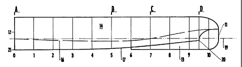
Referring to the drawings of the first embodiment of the
invention, FIGS. 1 and 2 show each of ten numbered vertical cross
sections or positions. A hull of a shipping (also called "boat") according
to the invention has a bow point 11 e.g. as a stem, a stern e.g. as a
Is transom 12, a keel 13, hull sides 14 and 15, a bottom 16, chines 17
and 18. The chines 17 and 18 are the points where the sides 14 and,
respectively, 15 meet the bottom 16. A stationary boat waterline is
designed in 19.
As shown in FIGS. 1 to 3, the bow point 11 is connected convexly
2o to the hull sides 14, 15 through convex shapes suitably connected.
The hull sides i4, 15 lie in vertical, parallel planes, that are
symmetrically opposed with respect to a diametral longitudinal plane
shown in a center fine X-X, and end aft at the stern 12. The stern 12 is
flat. However, a boat stern may be differently shaped.
Zs The hull sides 14 and 15 end downwards at the chines 17 and,
-9-
CA 02331366 2004-05-07
respectively, 18, being disposed laterally to the diametral longitudinal plane
and defining a lower edge of the same hull sides 14 and 15. Each chine 17,
18 begins in 20, in a cross section plane between positions 9 and 10,
thereafter defines a longitudinal curve extending continually aftward to the
stern 12 and ending in a point 21.
The keel 13 extends along the center line X-X on the underside of the
hull fore and aft in a portion between the bow point 11 and a boat position
6. Preferably, the keel 13 is tapered downwards, having symmetrical
biconvex contours 22 and 23, a leading edge 24 and a trailing edge 25
both suitably connected. The biconvex contours 22 and 23 have the
maximum chord in the second third of the length of the keel 13 from the
bow point 11. However, this configuration may be varied in order to
optimize design parameters. With regard to the position of the keel 13, it is
suitable that its leading edge 24 is situated in the bow point 11 and its
trailing edge 25 is situated in a cross section 6 ahead of the midship
section 5 by about a tenth of the length of the shipping on the waterline.
However, the position of the trailing edge 25 may be varied as required. In
the embodiment shown the keel 13 has its lower end lying in a horizontal
plane, where also the point 21 of the chines 17 and 18 lies. A different
project might require either a greater or lower draft.
The bottom 16, i. e. the underside of the hull according this
invention, has a surface extending laterally between the chines 17 and 18 in
the portion between the cross sections 0 to 6 and between each chine 17
and 18 and the keel 13 between the cross section 6 and the
-10-
CA 02331366 2000-11-03
WO 99/57006 PCTlIT99/00101
bow point 11. The surface of the bottom 16 has cross section planes
at right angles with the center line X-X, the cross section planes
forming convex bottom structures bridging the chines 17 and 18 each
other and with the keel 13. These convex bottom structures define a
s pair of inverted longitudinal channels 26 and 27 extending along both
contours 22 and 23 of the keel 13. As shown in FIG. 4D, each
longitudinal channel 26, 27 has a profile with channel sides deeply
rockered near the bow in the beginning point 20 of the chines 17, 18.
Aftward, e.g. as shown in FIG. 4C, the sides of the convex bottom
Io channels are inclined angularly with a less steep ramp in the external
channel side with respect to channel side defined by the keel 13. In
the section C-C the bottom of the channels 26 and 27 merges into a
single inverted convex bottom channel 28 aft from the keel. As shown
in FIG. 4B, the channel 28 has a profile with ever more inclined
Is angularly connected channel sides in the cross section toward stern. In
the stern 12, the channel sides become parallel to the hull sides 14
and 15 and then at right angles with the bottom 16.
Referring to FIGS. 2 and 3, a locus of greatest curvature of the
bottom channel sides is indicated in 29. The bottom 16 is so shaped to
Zo have a progressive cross section increase from stem to stern, first of
the pair of channels 26 and 27 and then of the single channel 28.
Thus the object of limiting the formation of the bow wave system
generated by the penetration of the keel in its motion into calm water
is achieved. Said wave system is conveyed between the two hull sides
2s 14 and 15 dipping under the waterline 19 at a suitable distance from
CA 02331366 2000-11-03
WO 99/57006 PCT/IT99/00101
the bow point 11.
Referring now to FIGS. 5, 6, 7, 8, 9E,F,G,H,I a second
embodiment of the hull having a mono-three-catamaran architecture is
shown. In figures similar parts to those of the first embodiment shown
s in FIGS. 1 to 4D are denoted by similar reference numerals.
As shown in FIGS. 5 to 7, hull sides 140, 150, similarly to the
first embodiment, lie in vertical, parallel planes, that are symmetrically
opposed with respect to a diametral longitudinal plane shown in a
center line X-X. However, bow point 110 is con~fected in front
to convexly and then concavely to the hull sides 140, 150, with a
consequence that a bow portion extends more widely than in the hull
of the first embodiment.
The hull sides 140 and 150 end downwards at chines 170 and,
respectively, 180, beginning in 200, in a cross section plane aft the
is position 08 (FIG. 5), thereafter the chines 170, 180 define a
longitudinal line extending continually aftward to the stern 120 and
ending in a point 210. The function of such a widened bow portion will
be explained below.
The keel 130 extends along the center line X-X on the underside
20 of the hull fore and aft. Preferably, the keel 130 is tapered
downwards, having symmetrical biconvex contours 220 and 230, a
leading edge 240 and a trailing edge 250. The keel 130 has cross
sections of a fusiform body.
The biconvex contours 220 and 230 have the maximum chord
2s about in the midway of the length of the keel 130. With regard to the
-12-
CA 02331366 2004-05-07
location of the keel 130, it is suitable that its leading edge 240 is situated
near
the bow point 110 and its trailing edge 250 is situated in a cross section
between a cross section 06 and the midship section 05, before the last one
by about a twentieth of the length of the shipping on the waterline.
However, the position of the trailing edge 250 may be varied as required. In
the second embodiment the keel 130 has its lower end lying in a horizontal
plane, where also the point 210 of the chines 170 and 180 lies. A different
project might require either a greater or lower draft.
Bottom 160, according to the second embodiment of this invention,
has a surface extending between the chines 170 and 180 in the portion
between the position 00 of the hull and the trailing edge 250 of the keel 130,
between each chine 170 and 180 and the keel 130 in the portion between the
trailing edge 250 and the position 08 of the hull, and toward the bow adjacent
to the same keel.
The structures forming the bottom 160 define a pair of inverted
longitudinal channels 260 and 270 extending along both contours 220 and
230 of the keel 130. As shown in FIG. 9I, each longitudinal channel 260, 270
begins with a profile with very flat channel sides. Aftward from position 08,
as shown in FIG. 9H, the hull sides 140, 150 dive sharply and the chines
170 and 180 are immediately at their maximum draft. From cross section H-H
to section G-G (FIG. 9G) the bottom bends down until the section of the
trailing edge 250 of the keel and the sides of the convex bottom channels tend
to be connected convexly on the external side with respect to the concave
-13-
CA 02331366 2000-11-03
WO 99/57006 PCT/IT99I00101
side defined by the keel 130. In the cross section of the trailing edge
250 the bottom 160 goes up again until the waterline 190 in the
position 00. From the same cross section of the trailing edge 250 of
the keel 130, the bottom of the channels 260 and 270 merges into a
s single inverted convex bottom channel 280.
As shown in cross section G-G, FIG. 9G, the channel 280 has a
profile with convex-flat-concave-flat sections until the center Ijne.
From the position 04 of the hull, the bottom is flattened going up and
the sides of the bottom channel 280 are increa~ngly inclined to
io become parallel to the hull sides 140 and 150 and then at right angles
with the bottom 160. Referring to FIGS. 5 and 6, a locus of greatest
curvature of the bottom channel sides is indicated in 290.
In the second embodiment of this invention, the particular
bottom profile with convex-flat-concave-flat sections serves to create
is discontinuity points for the pressure distribution in the underside of
the hull, that give the hull a greater stability than that of the hull of
the first embodiment.
Further, with respect to the first embodiment, the more
elongated and flattened bow allows the bow wave to be directed, held
ao by the sharply slanted downwards. The entrance of the channels 260
and 270 is much narrower with respect to the first embodiment, in
virtue of the much more thickened edge of the keel 130 in the bottom
160. This increases the function of diffuser of the bottom of the hull.
This configuration of the bow causes, in heavy sea, the bow wave to
Zs pass over the top of the bow so that the hull acquires a greater
-14-
CA 02331366 2000-11-03
WO 99157006 PCT/IT99/00101
stability since the wave over the bow is balanced by hydrostatic thrust
of the wave passing under the bow.
Such a structure permits that a hull may be developed for high
speed, e.g. in a range between 15 and 25 knots.
s Naturally also the hull sides according to the invention in the
motion form their system of diverging and transverse bow waves.
However, due to an asymmetry of said hull sides, in this bow wave
system, the portion of waves moving away from the boat is of only
slight importance, while the portion directed towards the center line is
to conveyed into the bottom channel, promoting the air-water inclusion
and then the formation of the above described foamy layer.
Furthermore, the configuration of the bottom surface with two
channels and a single channel aft from the keel, together with the
formation of the foamy layer, enables a part of the energy spent in the
Is formation of the bow wave system to be exploited as an increase of
the hydrodynamic sustentation, as above-mentioned.
Yet, the configuration of the bottom surface with two channels
and a single channel aft from the keel may be so made that the
resultant of the thrust due to the hydrodynamic sustentation passes
Zo through the center of buoyancy approximately in order to not generate
a trim variation both when the boat is stationary or is navigating in a
displacement way and when the boat is navigating in a gliding way. In
both situations the position of the boat is constant, i.e. with respect to
bow-heavy or squat; when the boat begins to move, the only change
2s in boat position is in the level of the waterline, that is lower.
-ls-
CA 02331366 2000-11-03
WO 99/57006 PCT/IT99/00101
Thanks to the greater stability than before, the pitching and then
the risk of slamming, i.e. the impact of the bottom of a ship's bow
hitting the water, is reduced. The pressure created under the bottom
constitutes an obstacle for this known phenomenon that appears as a
s pressure wave reflected from shoals.
As above described, a hull so shaped promotes a decrease of the
residual wave system after the transit of the boat, in virtue of .the
dampening effect of the foamy layer.
In order to increase both the consistency anc!' the bulk of the
to foamy layer and help a water flow inside the bottom channels, it is
suitable to locate a propulsor or more propulsors in the aft portion of
the keel. Thus in addition to the above-mentioned effect of air-water
inclusion, a suction phenomenon is created in the entrance of the
channels in the bottom of the boat. This suction phenomenon prevents
Is the water flow from blocking, which would cause a decrease of the
foamy layer and then an uncontrolled increase of the resistances to
forward motion.
A propulsor located under the bottom of the boat as above-
mentioned, enlarging a low pressure area in the entrance of two
2o bottom channels, helps waves to flow and then favours a navigation in
rough sea condition.
With respect to the propulsor it would be noted that for medium
tonnage shipping the propulsor may be suitably a jet drive having
ramming intake located in bottom channels between the keel and the
2s hull sides so to favour the suction effect, i.e. the depression in the
- 16-
CA 02331366 2000-11-03
WO 99/57006 PCT/tT99/00101
bow entrance. The exit of the jet drive may be suitably located just aft
the keel so to favour on one hand the formation of the foamy layer as
above described and to increase on the other hand the speed in the
single bottom channel between two hull sides with a consequent
s increase of the hydrodynamic sustentation and of water flow rate
through the same channel.
In higher tonnage shipping one or more propellers may be
placed also aft the keel with the same effects on water flow and then
on the efficiency of the shipping.
io When the propulsor is a sail, the central keel has a great draft
and owing to low potential speed the shape of the keel may have in its
low portion a wing profile at right angles with the keel in the aft
portion thereof. The bottom side of the wing profile is almost flat while
the upper side of the same is concave in order to promote the
is extension of the low pressure area toward stern, allowing the wave to
easily overcome the hull bottom in the point of its maximum draft.
Some advantages of the invention can be resumed as follows.
One of these advantages is a larger versatility in designing than
before, i.e. the hull may be developed for wider speed ranges.
2o Furthermore, a mono-three-catamaran hull, as expressed by a
neologism adopted in this specification has, in the performance with
respect to the wave systems, advantages of the three architectures:
mono-hull, catamaran and three-maran. The hull according to the
invention neither behaves as a supported beam on the waves as the
Zs mono-hulls, nor is subjected to torsional stresses as typical for the
_17_
CA 02331366 2000-11-03
WO 99/57006 PCT/IT99/00101
multi-hulls, that therefore are limited in their possibilities and carrying
capacities. Then, the mono-three-catamaran architecture, although it
is a mono-hull overcomes the structural drawbacks of the hulls above-
mentioned, while it acquires their advantages with respect to the
s hydrodynamic performance.