Note: Descriptions are shown in the official language in which they were submitted.
CA 02331397 2000-11-03
WO 99/57050 PC'T/FI99/00271
Cross-cutting apparatus and method~for a web-like material, as well as sheet
cutter
The present invention relates to a cross-cutting apparatus for a web-like mate-
s rial, such as a pulp or paper web, as well as to a cross-cutting method.
Further-
more, the invention relates to a sheet cutting unit.
In prior art cross-cutting mechanisms used in a pulp-drying machine, the cut-
ting process is based on a rotating cross-cutting blade and a solid counter-
blade. The aim is to produce a neat cutting trace. A goad cutting result
requires
permanently sharp blades and a controlled blade clearance. As the machines'
sizes keep increasing, specially their width, the control of a btade clearance
becomes increasingly difficult, perhaps even impossible. In any event, a
techni
cal solution will be very expensive in currently available equipment involving
a
rotary cutting blade and a counter-blade. At the point of cutting, a pulp web
is
subjected to a compression between the blades before the web is severed. In
such a cutting operation, the edge areas of a sheet experience contraction of
the pulp material and develop material lumps ("fish-eyes"). Such material
lumps are not desirable in view of the further processing of a pulp sheet,
whereas the cutting results itself need not be particularly good since, after
all,
the severed pulp sheet will be processed further.
An object of the present invention is to provide an enhanced cross-cutting
apparatus for a pulp web, which will also be simpler and more effective than
currently available equipment in terms of its operation and maintenance.
The basic conception in an apparatus and method of the invention is that it
comprises means for maintaining a web tension at a cutting point as well as a
blade assembly capable of piercing a web for cutting the same.
An apparatus of the invention is characterized in that the apparatus comprises
at least
- means (1, 3) for maintaining the tension of a web (4) at the cutting moment,
as well as
CA 02331397 2000-11-03
WO 99/57050 PCT/F199/00271
2
- an assembly capable of crosswise cutting the web, comprising
- at least a web-supporting assembly (2) on one side of the web (4}, and
- at least one web-piercing blade element (5) on the essentially opposite
side thereof,
wherein said web-supporting assembly (2) includes at least one
arrangement (6) for allowing the piercing action of the blade element (5) to
extend through the web (4) in such a way that it is simultaneously supported
in the vicinity of a piercing area.
In a preferred embodiment, the apparatus comprises two pairs of web-
tensioning rotating rolls spaced from each other in the web running direction,
as well as there between a pair of rotating cross-cutting rolls, the web being
guided through said pairs of rolls, and that one of the cutting rolls is
provided
with at least one web-piercing blade element extending from the
circumferential
roll surface and one of the web-supporting rolls has its circumferential
surface
provided with at least one groove or slot in cooperation with said blade ele-
ment.
In a further embodiment of the invention the upstream pair of drawing rolls
has
a speed of rotation which is lower than that of the downstream pair of drawing
rolls.
An apparatus of the invention is based on the piercing of a web, not cutting
it.
A requirement for piercing is that the web be tensioned at the point of
piercing
for driving the piercing blade easily into and through the web.
With regard to conventional equipment provided with rotary cutting blades and
counter blades, the apparatus of the invention is less noisy and, furthermore,
the apparatus can be designed by using lighter, thin-walled rolls or
cylinders.
In a preferred embodiment of the invention, the blade element or elements are
included in an upper cutting roll and the groove or grooves respectively in a
lower cutting roll.
CA 02331397 2000-11-03
WO 99/57050 PCT/FI99/00271
3
The construction of rolls used in a recommended embodiment can be designed
in such a way that the web-supporting frame of a cutting roll is provided with
circumferential grooves and, respectively, the circumferential surface of a
roll
thereabove is provided with piercing blades matching the grooves.
Another advantage gained by the invention is that, if necessary, the number of
blades can be increased, such number being generally 1-4. The counter-roll
can be provided with a corresponding number of grooves or a single groove, a
speed difference between the rolls being used for bringing the piercing blade
to
always find a groove present on the frame.
The above-described continuously rotating roll can also be replaced by using a
linkage performing 'a reciprocating action. This type of solution can be imple-
mented e.g. in such a way that on one side of a web (either above or below) is
a continuously rotating roll provided with a piercing blade and a piercing
slot is
included in a linkage functioning as a counterpart for the roll and having an
arched top surface which is provided with a crosswise slot over the length of
the piercing blade, which is able to receive the blade in a pierce-cut
operation.
At its simplest, the linkage may operate in such a manner that the blade of
roll
of a rotating blade roll "drives" the linkage. Pulled by the blade roll, the
linkage
swings from a start position to set against a cushion while the cut-through
takes place. After the cutting, the linkage returns to its start position,
e.g. by
means of a spring force. A blade bar can also be constructed by using a
similar
linkage, whereby both the blade bar and a counter-bar take the form of recipro-
Gating linkages.
In embodiments with several blades, the blades can be adapted to be retract-
able, whereby it is readily possible to use one and the same apparatus for
running sheets of various sizes. These may be necessary if, for example, it is
desirable to wrap a pulp bale in the same pulp as the contents of the bale,
the
cutter of the invention being readily capable of running bale wrappers (=
larger
sheets) by retracting some of the blades, even while the machine is running.
CA 02331397 2000-11-03
WO 99/57050 PCT/FI99/00271
4
In the construction of the invention, it is not necessary to undertake a blade
adjustment, which is a major practical advantage. The replacement of a blade
in a pulp mill may take up to six hours and such a blade has an operating life
from about 3 months to 1 year, depending on how much it is used.
The invention relates also to a method for the continuous-action cutting of a
web-like material, such as a web of pulp or the like. This method is character-
ized in that the web is maintained in a tensioned condition and pierced cross-
wise of the web with a blade element in one or more operations at the same
point of the web, and that the web is supported during the piercing process at
the point of piercing in such a way that the blade element is able to
penetrate
through the web essentially throughout its cross machine direction.
In the method, the tension of a web is maintained in such a way that the pierc-
ing blade does not alter the main running direction of the web.
Furthermore, the invention relates to a continuous working sheet cutter unit
in a
pulp-drying machine, comprising at least
- a slitter mechanism for a pulp web for cutting it in a number of laterally
adjusted slitting devices into separate longitudinal webs,
- a pair of drawing rolls or the like for maintaining in the dryer section a
de-
sired web tightness and for drawing the web,
- a cross-cutting device for cutting the separate webs into sheets,
- an overlapping device for sheets, wherein the sheets are overlapped for
reducing the speed of the pulp web, as well as
- a bale table or the like for stacking the sheets thereon to produce bales.
This sheet cutter unit is characterized in that the cross-cutting device, in
which
the separate webs are cut into sheets, comprises at least
- a web-supporting assembly on one side of the web,
- a web-piercing blade element on the essentially opposite side thereof,
the web-supporting assembly comprising an arrangement for allowing a
piercing action of the blade element to extend through the web while simul-
taneously supporting it in the operative vicinity of a piercing location,
CA 02331397 2000-11-03
WO 99/57050 PCT/FI99/00271
- an assembly for adjusting/setting the web to a predetermined tension at the
web cutting moment.
The invention will now be described in more detail with reference made to the
5 accompanying drawings, in which
fig. 1 shows an apparatus of the invention in one embodiment,
figs. 2 and 3 show a second preferred embodiment of the invention,
fig. 4 shows a further embodiment of the invention, wherein one of the blades
is retractable,
fig. 5 shows a solution of the invention, wherein the cutting of a web is per-
formed in two separate operations,
figs. 6 and 7 show details of fig. 5 embodiment, and
fig. 8 shows a sheet cutter unit of the invention.
The apparatus of the invention is based on the fact that a web is not cut with
a
blade, but a web is pierced, the requirement of which is that the web is
tensioned at the moment and area of piercing.
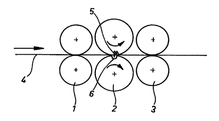
Fig. 1 depicts a fundamental solution for such an apparatus of the invention.
In the running direction of a pulp web 4 there are two spaced-apart pairs of
rolls 1 and 3, the web 4 being guided therethrough. The downstream pair rolls
3 has a rotating speed which is higher than that of the first pair of rolls 1,
the
web 4 becoming tighter between these pairs of rolls.
Between the pars of rolls 1 and 3 is fitted a second pair of rolls 2, wherein
the
upper roll has its outer frame provided with a piercing blade 5 extending from
the frame. The lower roll 2, which supports the web 4, is provided with a cir-
CA 02331397 2000-11-03
WO 99/57050 PCT/FI99/00271
6
cumferential recess 6 which is in cooperation with the piercing blade 5 of the
upper roll in such a way that, as the upper roll is rotating, the piercing
means 5
and the recess 6 coincide with each other at the web, the piercing means 5
penetrating into the web and piercing the same.
Fig. 1 illustrates just one piercing means 5, but the number can be increased
as the case may be, the practical number of blades being 1-4 as illustrated in
fig. 4. Respectively, the lower roll 2 can be provided with an equivalent
number
of counter-grooves 6 for the piercing means 5.
Figs. 2 and 3 illustrate an embodiment of the invention, wherein a web passes
through between a roll provided with a blade 5 and a back-up element 11 set
therebelow and provided with a web-supporting bearing surface. In this em-
bodiment, the bearing surface is not constituted by a roll but, instead, by
the
link-shaped back-up element 11, having its peripheral surface provided with a
groove 6 in cooperation with the blade 5. At its base, the back-up element 11
is
hinged to a support assembly and operates reciprocally along a path defined
by two limiters 12.
In fig. 2, the back-up element 11 is in its start position against a left-hand
cush
ion member 12 , in which position the overhead blade 5 coincides with the
groove 6 present in the bearing surface upon pressing through a web 4.
As the roll 2 is rotating, the back-up element 11 turns along with the blade 5
and is released therefrom, as shown in fig. 3, as the back-up element comes
into contact with the right-hand limiter 12. In this position, a spring 13
pulls the
back-up element 11 back to the start position.
In the embodiment shown in figs. 2 and 3, the link-shaped back-up element 11
operates continuously, being driven by the rotating overhead roll. It is also
possible that such a linkage can be operated mechanically.
Fig. 4 depicts one embodiment in reference to four crosswise blades. One of
the full-width blades 5 is positioned in a groove-like recess, having such a
CA 02331397 2000-11-03
WO 99/57050 PC'T/FI99/00271
7
depth that the blade 5 can be fully retracted within the recess. The blade 5
is
adapted to be movable in and out in contact with guide surFaces. In this em-
bodiment, the actuator is constituted by a number of electrically controlled
solenoids 25, capable of retracting the blade even while the machine is run-
s ning, if this is desirable. The loading is effected for example by means of
a
spring, which normally maintains the blade extended as the web is pierced.
The actuator, such as the solenoids 25, is sufficiently powerful for
retracting the
blade against the spring load. The blades are typically maintained extended
but, in special circumstances, the solution of the invention can be readily
switched for running sheets of a different size, such as bale wrapping sheets.
By way of a transfer path extending through a shaft the actuator (actuators)
is
connected to a control unit for controlling the position of blades.
Figs. 5-7 illustrate an embodiment of the invention, wherein a web is cross-
cut
in several sequences. This is shown schematically in fig. 5.
Fig. 6 shows the point of piercing in a view transversal to the running
direction
of a web 4. The apparatus is provided with a back-up plate 7 for the web 4.
The back-up plate 7 constitutes an opening or a recess 6 at the point of pierc-
ing, wherein a web-supporting roll 2 is able to make a contact with the web.
The roll 2 is provided with circumferentially extending grooves 10, which
corre-
spond to the transversal groove 6 in the surface of the roll 2 shown in fig:
1.
The circumferentially extending grooves are parallel to each other and corre-
spond in number to the number of piercing blades 5 included in the overhead
roll.
The piercing blades can be positioned in a number of rows spaced from each
other in the running direction of the web. The embodiment shown in figs. 5-7
includes blade arrays 5, 50 which are set in two successive rows (fig. 5) in
line
with the longitudinal axis of the overhead roll. In line with the blades 5, 50
and
below the web 4 there are back-up rolls 2, 20, respectively.
The blade position can be adjusted by means of an adjustment and fastening
screw 9 extending through a slot 8. Likewise, the blade is quite easy to
replace.
CA 02331397 2000-11-03
WO 99/57050 PCT/FI99/00271
8
The blade wears very little and, thus, it is very seldom that the blade must
be
replaced.
Fig. 7 illustrates the embodiment of fig. 6 as seen in the web running
direction.
Fig. 7 depicts a slotted design of the lower roll and the positioning of the
pierc-
ing blades 5, 50 in line with grooves 10 extending around the circumference
thereof. Depending on the width of a web, the number of blades can be 1-4.
The continuous sheet cutter unit of the invention, used in a pulp-drying ma-
chine and shown schematically in fig. 8, comprises a tail feed device 14 for a
pulp web 4, which is preferably mounted in connection with the cutter unit and
to which the web is delivered from a dryer section. Normally the web merely
runs past the tail feed device, which is not needed except in a feed
situation.
Subsequently, in a cutter unit of the invention, the web 4 is advanced to a
slitter
assembly 15 for slitting the same with a number of laterally mounted slitting
devices into separate longitudinal webs. The slitting width is determined ac-
cording to what is desirable in a particular type of slitting. After the
slitting, the
separate webs are carried further to a pair of drawing rolls 1, which
maintains
over a dryer section a desired web tension and draws the web (at this point,
slit
separate webs). From the pair of drawing rolls 1 the longitudinally slit
separate
webs are fed to a cross-cutting piercing device 2 of the invention for cutting
the
separate webs into sheets by piercing in accordance with the invention.
The cross-cutting piercing device of the invention for cutting separate webs
into
sheets comprises at least a web-supporting assembly 2 on one side of a web
4, a web-piercing blade element 5 on the essentially opposite side thereof,
said web-supporting assembly 2 comprising an arrangement 6 for allowing a
piercing action of the blade element to extend through the web 4 while support-
ing the same in the functional vicinity of the piercing area, as well as a
mecha-
nism 20 for adjusting/setting the web to a predetermined tension at the mo-
ment of cutting the web.
According to the invention, downstream of the piercing-cutting unit 2 is a sec-
ond pair of drawing rolls 3 for maintaining a desired tension in the cross-
cutting
CA 02331397 2000-11-03
WO 99/57050 PCT/FI99/00271
9
apparatus as well as for guiding cut sheets 16 further, if necessary in an
over-
lapping fashion, onto a bale table, whereby it is also possible to use a
separate
set of drawing rolls 17 for overlapping. When a reject gate/gates 19 in connec-
tion with the pair of drawing rolls 3 are closed, the sheets 16 runs forward
in
the process over a normal path to the support rolls of a sheet conveyor and
further onto a bale table 18.
The continuous sheet cutter unit of the invention used in a pulp-drying
machine
is capable of eliminating several drawbacks existing in the prior art
architecture.
The use of a sheet cutter unit of the invention entails, for example, that it
is not
necessary to build a complicated temperature stabilizing unit for the counter-
blade, which means savings in terms of space, energy, as well as investment
costs. The sheet cutter unit of the invention is also significantly less noisy
than
the prior art solutions. There is more freedom in designing a sheet cutter
unit of
the invention, as it does not require a downward path run to the cutter, which
is
the case in the prior art solution.