Note: Descriptions are shown in the official language in which they were submitted.
CA 02331490 2000-11-09
WO 99/58962 PCT/US99/10279
IMPROVED APPARATUS AND METHODS FOR CARRYING OUT
ELECTROCHEMILUMINESCENCE TEST MEASUREMENTS
BACKGROUND OF THE INVENTION
Field of the Invention
This application relates generally to apparatus and methods for detecting and
measuring analytes of interest by inducing electrochemiluminescence (ECL) in a
test
sample and detecting the resulting light.
Numerous methods and systems have been developed for detecting and
quantitating analytes of interest in chemical, biochemical, biological, and
environmental samples. Methods and systems that are capable of measuring
toxins,
environmental contaminants, pharmacological agents, bioactive substances,
metabolites, pathogenic organisms, proteins and nucleic acids are of
substantial value
to researchers and clinicians. At this time, there are a number of
commercially
available instruments that utilize ECL for analytical measurements. These
instruments have demonstrated exceptional performance.
The high cost, complex engineering and long development time required to
custom-design and manufacture ECL instruments have delayed broad
implementation of ECL technology. Clearly, there remains a need for ECL
subsystems or modules that can be easily adapted to a broad variety of
different
applications.
Current needs for precision analytical testing instrumentation are
extraordinarily diverse. For example, pharmaceutical screening analyses
require
instruments that can perform large numbers of analyses at very high speeds on
very
small quantities of sample. In addition, such instruments may need to perform
many
different types of highly sensitive quantitative tests utilizing different
detection
methods. Similarly, clinical diagnostic analyses for human health care
typically
require highly sensitive and exceptionally reliable instrumentation. In
contrast, it is
expected that commercial instruments intended for field use would be small,
perhaps
portable, simple to use, and operable with only limited power. Low production
and
maintenance costs are often predominant considerations.
CA 02331490 2000-11-09
WO 99/58962 PCT/US99/10279
2
Description of the Prior Art
An apparatus for carrying out electrochemiluminescence test measurements is
found in U.S. Patent No. 5,466,416 assigned to IGEN, Inc. A cross-sectional
view of
a flow cell is depicted in Figure 1. Flow cell 18 comprises a removable plug
20, a
gasket 22, a retainer block 24, a counter electrode 26, an ECL test chamber
28, a
working electrode 30, a transparent block 32, a counter electrode 34, a
retainer block
36, a conduit 46, a main housing 48, a chamber 40, a lateral block 42, a frit
44, a
gasket 50, a plug 52, an O-ring seal 56, a threaded coupling 58, a conduit 60,
a pivot
arm 61, a magnet 62, and a threaded coupling 64.
Flow cell 18 includes a main housing 48 formed of a durable, transparent and
chemically inert material such as acrylic or polymethyl methacrylate. Threaded
coupling 64 defines a fluid inlet in a lower surface of housing 48 and is
contiguous
with conduit 46. Conduit 46 extends through housing 48 from coupling 64 to an
upper surface of housing 48. Threaded coupling 58 defines a fluid outlet in a
lower
surface of housing 48 and is contiguous with conduit 60. Conduit 60 extends
through
housing 48 from coupling 58 to the upper surface of housing 48. ECL test
chamber
28 is bounded by the upper surface of housing 48, a lower surface of block 32,
lower
and side surfaces of counter electrodes 26 and 34, the upper surface of
working
electrode 30, and the interior surface of gasket 22. Chamber 28 communicates
with
both conduit 60 and conduit 46. Fluid introduced through coupling 64 may
travel
through conduit 46 to chamber 28 and exit through conduit 60 and coupling 58.
Working electrode 30, counter electrode 26, and counter electrode 34 may
consist of electrically-conductive materials such as platinum or gold. Working
electrode 30 has a generally flat, elongate, rectangular shape having a
longitudinal
axis arranged generally transverse to a longitudinal axis of chamber 28.
Electrode 30
is positioned centrally between conduits 60 and 46 in a shallow groove formed
in the
upper surface of housing 48. An adhesive (not shown) bonds electrode 30 to the
groove in housing 48. Accordingly, at least three seams between electrode 30
and
housing 48 abut chamber 28; one on each latitudinal side of electrode 30 and a
third at
a longitudinal end of electrode 30. As displayed in Figure 1, electrode 30 is
approximately as wide as the gap between counter electrodes 26 and 34 and is
positioned centrally therebetween.
CA 02331490 2000-11-09
WO 99/58962 PCT/US99/10279
3
Counter electrodes 26 and 34 have an "L"-shaped cross-section, the shorter
arm having a length slightly longer than the thickness of block 32 and the
longer arm
having a length of less than half of the width of block 32. The two arms of
each
electrode are flat, thin and positioned perpendicular to each other but in
different
planes. The widths of electrodes 26 and 34 are approximately less than half of
the
thickness of block 32. Counter electrode 26 is affixed to a side of
transparent block
32 and is held in place by retainer block 24. On the opposite side of
transparent block
32, counter electrode 34 is similarly affixed by retainer block 36.
Magnet 62 is affixed to pivot arm 61. In its raised position, pivot arm 61
positions magnet 62 beneath working electrode 30, sandwiching a segment of
housing
48 therebetween. In its lowered position, pivot arm 61 pivots down and away
from
housing 48 thereby significantly increasing the distance between working
electrode 30
and magnet 62.
A reference electrode assembly, integrated into housing 48, comprises
chamber 40, block 42, gasket S0, frit 44, plug 52, and gasket 56. An ionic
fluid (not
shown) is retained within chamber 40. Chamber 40 comprises a cavity defined by
housing 48, gasket 50 and block 42. Frit 44 extends into conduit 60 and is
sealed by
O-ring 56 and plug 52 to prevent fluidic interchange.
A refill aperture (not shown) is provided in housing 48 to allow replacement
of the ionic fluid held in chamber 40. The refill aperture is sealed by
removable plug
20. To achieve useful and reproducible ECL test measurements, flow cell 18
utilized
a temperature-controlled environment. Figure 2 illustrates an apparatus 80
from U.S.
Patent No. 5,466,416 for providing a temperature-controlled environment for
flow
cell 18. Apparatus 80 comprises a photomultiplier tube (PMT) 82, an insulating
cover
92, a housing 94, a plurality of foil heaters 96, a circuit board 84, flow
cell 18, a
magnet 62, a pivot arm 61, a linear actuator 98, a coil spring 102, an air
space 90, and
a fan 104. For reference purposes, housing 48, block 42, retainer block 24,
counter
electrode 26, and block 32 are specifically labelled on flow cell 18.
Foil heaters 96 are positioned on the outer lateral surfaces and the outer
lower
surface of housing 94. The upper surface of housing 94 adjacent PMT 82 is
formed
of a transparent material while the remaining portions of housing 94 are
preferable
opaque. Insulating cover 92 covers foil heaters 96 as well as the remaining
uncovered
CA 02331490 2000-11-09
WO 99/58962 PCT/US99/10279
4
outer surfaces of housing 94 to provide thermal insulation and prevent the
entry of
light into flow cell 18. PMT 82 is a conventional photomultiplier tube mounted
on
the upper surface of housing 94. PMT 82 is physically large compared to the
size of
the flow cell, requires a high-voltage power supply, and is highly sensitive
to the
surrounding temperature and the presence of magnetic fields. It is preferable
that
PMT 82 be maintained at a relatively low temperature. Flow cell 18 is
positioned
below PMT 82 inside temperature-controlled housing 94.
Circuit board 84, incorporating operating electronics for apparatus 80, is
mounted on an interior surface of housing 94 adjacent flow cell 18. As shown,
linear
actuator 98 is connected to coil spring 102 which, in turn, is connected to
pivot arm
61. Magnet 62 is affixed to an end of pivot arm 61.
The temperature within housing 94 is controlled through the operation of foil
heaters 96 in conjunction with fan 104. Fan 104, affixed to the interior
surface of
housing 94, circulates air within air space 90. Air space 90 extends
throughout the
interior of housing 94 and surrounds each component therein, including,
specifically,
flow cell 18. Air space 90 further includes an air gap between the upper
surface of
flow cell 18, e.g., block 32, and the upper interior surface of housing 94.
As described above, pivot arm 61, shown in its lowered position, can pivot
upward to place magnet 62 within housing 48 of flow cell 18. Linear actuator
98,
operating in conjunction with coil spring 102, causes pivot arm 61 to move.
In an ordinary operation, magnet 62 is raised into a position adjacent to
working electrode 30 of flow cell 18 to attract magnetic particles in an assay
fluid in
chamber 28 to the vicinity of working electrode 30. Shortly thereafter, to
avoid
magnetic interference with the operation of PMT 82, magnet 62 is withdrawn
from
flow cell 18 prior to the induction of electrochemiluminescence in the assay
sample
fluid. Conventionally, magnet 62 is not positioned to collect magnetic
particles
during the application of electrical energy to the assay fluid. Magnet 62 is
usually
retracted before electrochemiluminescence is induced to avoid magnetic
interference
with ECL measurements by PMT 82. Removal of the magnetic field from working
electrode 30 may allow a flowing assay sample fluid to carry away magnetic
particles
collected there.
CA 02331490 2000-11-09
WO 99/58962 PCT/US99/10279
Methods of calibration for apparatus 80 convolve diagnosis of the
effectiveness of bead capture and the effectiveness of the ECL cell.
Therefore,
calibration is preferably achieved using bead-based standards (e.g. magnetic
beads
coated with ECL labels).
As shown, apparatus 80 includes thermal insulation between PMT 82 and flow
cell 18. PMT 82 is very temperature-sensitive in that heat increases the
background
noise signal generated by PMT 82. Typically, PMT 82 is maintained in a
moderate to
low temperature environment. Since the ECL process generates considerable
heat,
flow cell 18 is thermally isolated from PMT 82. The use of thermal insulating
material between flow cell 18 and PMT 82 increases the length of the optical
path
from working electrode 30 to PMT 82 and, therefore, reduces the efficiency
with
which light emitted at working electrode 30 is transmitted to PMT 82.
Additionally, it should be readily apparent that the optical path between
chamber 28 of flow cell 18 and PMT 82 includes multiple air-solid and solid-
solid
boundaries. These transitions between media reduce the amount of ECL-generated
light which ultimately reaches PMT 82. Light generated between counter
electrode
26 and working electrode 30 or between counter electrode 34 and working
electrode
30 passes from the assay fluid in chamber 28 through a bottom surface of block
32,
through the bulk of block 32 and through the upper surface of block 32. At the
lower
surface of block 32, light is reflected back towards housing 48 and, in
particular,
working electrode 30. Light travelling through the bulk of block 32 is
diffused and
may be gradually separated into component wavelengths. At the upper surface of
block 32, a portion of the incident light is internally reflected back into
the bulk of
block 32 while the remainder is transmitted into air space 90. Additionally,
at the
boundary between block 32 and air space 90, the light rays will be bent away
from
PMT 82 due to the decrease in refractive index across the boundary.
Consequently,
the amount of light directed towards PMT 82 is reduced.
The light travels through air space 90 to the lower surface of housing 94
where, again, some light is reflected back towards flow cell 18 while the
remainder is
transmitted into the bulk of housing 94. Within the bulk of housing 94, the
light is
diffused and may be further caused to separate into component wavelengths. At
the
upper surface of housing 94, where PMT 82 abuts housing 94, a portion of the
light is
CA 02331490 2000-11-09
WO 99/58962 PCT/US99/10279
6
internally reflected into the bulk of housing 94 while a remainder portion is
transmitted to PMT 82. The aforedescribed diffusion, bending, and reflection
of light
may significantly reduce the amount of ECL-generated light which is actually
incident upon PMT 82.
As shown, flow cell 18 includes electrode-housing seams within ECL chamber
28. The adhesive present at these seams and used to affix working electrode 30
to
housing 48 may deteriorate and erode over time. As a result, assay fluid
components,
cleaning fluid components, or other materials may collect in the seams between
electrode 30 and housing 48. The collected materials may react with or
otherwise
contaminate components of subsequent assays and thereby affect assay results.
OBJECTS OF THE INVENTION
It is, therefore, a primary object of the present invention to provide
apparatus
and methodology for carrying out improved electrochemiluminescence test
measurements.
A further object of the invention is to provide apparatus and methodology for
the efficient detection of light generated during an electrochemiluminescence
assay.
Still a further and related object of the invention is to provide a modular
ECL
measurement apparatus for rapid and efficient incorporation into an
application-
specific diagnostic device.
Another object of the invention is to provide apparatus and methodology for
conducting electrochemiluminescence test measurements under conditions of
continuous fluid flow upon an assay sample containing magnetic particles.
A still further object of the invention is to provide apparatus and
methodology
for applying a magnetic field to assay materials during the induction of
electrochemiluminescence and simultaneously detecting the light generated
thereby.
Another object of the invention is to provide apparatus that integrates each
of
the components needed to perform an ECL measurement in a single open-
architecture
ECL module.
Yet another object of the invention is to provide a modular apparatus for
carrying out an ECL measurement that comprises a modular system interface.
CA 02331490 2000-11-09
WO 99/58962 PCTNS99/10279
7
A further object of the invention is to provide apparatus and methodology for
an integrated system for assaying one or more samples for one or more analytes
of
interest.
A related object of the invention is to provide apparatus for conducting
S multiple simultaneous or near-simultaneous ECL measurements and for sharing
an
assay sample sampling device, a power supply, a controller, a system
interface, and a
user interface.
An additional object of the invention is to provide apparatus and methodology
for normalizing the operations of two or more ECL modules.
Another object of the invention is to provide an apparatus for ECL
measurements that comprises a modular system interface that is adapted for
convenient coupling to other analytical or processing devices.
Another object of the invention is to provide apparatus and systems capable of
detecting analytes in a sample by means of electrochemiluminescence and one or
more other analytical techniques.
Still another object of the invention is to provide an integrated system for
processing samples, amplifying nucleic acids, and measuring nucleic acids.
SUMMARY OF THE INVENTION
These and other objects of the invention are achieved in an apparatus for the
conduct of electrochemiluminescence measurements which includes a cell having
at
least one cell wall which includes a transparent portion adjacent to an ECL
chamber
defined within the cell, a working electrode abutting the ECL chamber and in
optical
registration with the transparent portion, a counter electrode abutting the
ECL
chamber and an electrically-shielded window adjacent to and in optical
registration
with the transparent portion of the cell wall.
The apparatus of the invention may also include a photodetector, e.g. a
photodiode, in optical registration with the electrically-shielded window, the
transparent portion of the cell wall and the working electrode.
In preferred embodiments of the invention, the working electrode is
removably fitted within the cell and has a planar electrode surface abutting
the ECL
chamber such that no seam is created between the working electrode and the ECL
CA 02331490 2000-11-09
WO 99/58962 PCT/US99/10279
8
chamber. A removable magnet is provided for applying a magnetic field to the
working electrode.
The object of creating an integrated system for assaying a sample or plurality
of samples for a plurality of analytes of interest is also achieved in systems
comprising a plurality of modules which may share a common sample handling
subsystem, a common power supply, a common controller and/or a common system
or user interface.
According to an aspect of the present invention an apparatus for the conduct
of
electrochemiluminescence measurements includes a cell having at least one cell
wall
which includes a transparent portion adjacent to an ECL chamber defined within
the
cell, a working electrode abutting the ECL chamber and in optical registration
with
the transparent portion, a counter electrode abutting the ECL chamber, and an
electrically-shielded window adjacent to and in optical registration with the
transparent portion.
According to another aspect of the present invention an apparatus for the
conduct of electrochemiluminescence measurements includes a cell having at
least
one cell wall which includes a transparent portion adjacent to an ECL chamber
defined within the cell, a working electrode abutting the ECL chamber and in
optical
registration with the transparent portion, a counter electrode abutting the
ECL
chamber, a photodiode in optical registration with the transparent portion,
and an
optical filter adjacent to and in optical registration with the transparent
portion.
According to another aspect of the present invention an apparatus for the
conduct of electrochemiluminescence measurements includes a cell having at
least
one cell wall which includes a transparent portion adjacent to an ECL chamber
defined within the cell, a working electrode abutting the ECL chamber and in
optical
registration with the transparent portion, and a counter electrode abutting
the ECL
chamber and having an aperture in optical registration with the transparent
portion.
According to still another aspect of the present invention an apparatus for
the
conduct of electrochemiluminescence measurements includes a cell having at
least
one cell wall which includes a transparent portion adjacent to an ECL chamber
defined within the cell, a working electrode abutting the ECL chamber and in
optical
registration with the transparent portion, and a counter electrode abutting
the ECL
CA 02331490 2000-11-09
WO 99/58962 PCT/US99/10279
9
chamber, wherein the working electrode is removably fitted within the cell and
has a
planar electrode surface abutting the ECL chamber.
According to still another aspect of the present invention an apparatus for
the
conduct of electrochemiluminescence measurements includes a cell having at
least
one cell wall which includes a transparent portion adjacent to an ECL chamber
defined within the cell, a working electrode having a planar electrode surface
abutting
the ECL chamber and in optical registration with the transparent portion of
the cell
wall, the working electrode being positioned within the cell such that no seam
between the working electrode and the cell abuts the ECL chamber, and a
counter
electrode abutting the ECL chamber.
According to still another aspect of the present invention an apparatus for
the
conduct of electrochemiluminescence measurements includes a cell having at
least
one cell wall which includes a transparent portion adjacent to an ECL chamber
defined within the cell, a working electrode abutting the ECL chamber and in
optical
registration with the transparent portion, a counter electrode abutting the
ECL
chamber, a photodiode adjacent to and in optical registration with the
transparent
portion, and a magnetic field generating device operable to apply a magnetic
field at
the working electrode.
According to yet another aspect of the present invention an apparatus for the
conduct of electrochemiluminescence measurements includes a cell having at
least
one cell wall which includes a transparent portion adjacent to an ECL chamber
defined within the cell, a working electrode abutting the ECL chamber and in
optical
registration with the transparent portion, a counter electrode abutting the
ECL
chamber, and a photodiode adjacent to and in optical registration with the
transparent
portion, the photodiode having a detection sensitivity substantially limited
to light
having a wavelength in a range of 400 nm to 900 nm.
According to yet another aspect of the present invention an apparatus for the
conduct of electrochemiluminescence measurements includes a cell having at
least
one cell wall which includes a transparent portion adjacent to an ECL chamber
defined within the cell, a working electrode abutting the ECL chamber and in
optical
registration with the transparent portion, a counter electrode abutting the
ECL
chamber and having an aperture in optical registration with the transparent
portion, a
CA 02331490 2000-11-09
WO 99/58962 PCTNS99/10279
photodetector adjacent to and in optical registration with the transparent
portion, and a
magnetic field generating device, in registration with the aperture, operable
to apply a
magnetic field to the working electrode.
According to another aspect of the present invention an apparatus for the
5 conduct of electrochemiluminescence measurements includes a cell having at
least
one cell wall which includes a transparent portion adjacent to an ECL chamber
defined within the cell, a working electrode abutting the ECL chamber and in
optical
registration with the transparent portion, a counter electrode abutting the
ECL
chamber, a photodiode adjacent to and in optical registration with the
transparent
10 portion, a magnetic field generating device operable to apply a magnetic
field to the
working electrode, and a magnetic field detector, in registration with the
magnet
device.
According to another aspect of the present invention an apparatus for the
conduct of electrochemiluminescence measurements includes a cell having at
least
one cell wall which includes a transparent portion adjacent to an ECL chamber
defined within the cell, a working electrode abutting the ECL chamber and in
optical
registration with the transparent portion, a counter electrode abutting the
ECL
chamber, a photodiode, adjacent to and in optical registration with the
transparent
portion, for detecting electrochemiluminescence induced in an assay fluid in
the ECL
chamber and for producing an ECL signal representative of an intensity of the
electrochemiluminescence, a storage device, coupled to the photodiode, in
which a
calibration signal representative of a calibration electrochemiluminescence
may be
stored, and a processor, coupled to the photodiode and to the storage device,
operable
to calculate an intensity value as a function of the ECL signal and the
calibration
signal.
According to another aspect of the present invention a cell for the conduct of
electrochemiluminescence measurements includes a first base having a first
interior
surface, a planar working electrode positioned on the first interior surface,
a second
base having a second interior surface and having a transparent portion therein
to allow
light to pass therethrough, a planar counter electrode positioned on the
second interior
surface, the counter electrode having at least one opening therein to allow
the light to
pass therethrough in registration with the working electrode and the
transparent
CA 02331490 2000-11-09
WO 99/58962 PCT/US99/1OZ79
11
portion of the second base, a gasket positioned between the working electrode
and the
counter electrode to define therebetween a cell volume, the volume
communicating
with the opening in the counter electrode, and a retaining device, coupled to
the bases,
wherein the interior surfaces of the bases are in opposing relationship to
form the cell
and wherein the second base includes a conduit through which fluid may be
introduced into and removed from the cell volume.
According to another aspect of the present invention a cell for the conduct of
electrochemiluminescence includes cell structural elements, a working
electrode and a
counter electrode, at least one of the structural elements having a
transparent portion
therein, wherein the working electrode is mounted on an interior surface of a
structural element, a portion of the working electrode and the transparent
portion of
the at least one structural element defining, at least in part, a chamber for
the conduct
of electrochemiluminescence, the working electrode including the entirety of a
continuous planar surface of the chamber and the portion of the working
electrode and
the transparent portion of the structural element being optically in
registration with
one another.
According to another aspect of the present invention a method for conducting
an ECL measurement includes the steps of introducing an assay sample into an
ECL
chamber within a flow cell, simultaneously applying an electric field and a
magnetic
field to the assay sample in the ECL chamber, and measuring, through an
electrically-
shielded window defining a wall of said ECL chamber, electrochemiluminescence
induced in the assay fluid in the ECL chamber while the electric field and the
magnetic field are applied.
According to another aspect of the present invention a method for conducting
an ECL measurement includes the steps of introducing an assay sample into an
ECL
chamber within a flow cell, simultaneously applying an electric field and a
magnetic
field to the assay sample in the ECL chamber, and measuring with a
semiconductor
photodetector electrochemiluminescence induced in the assay fluid in the ECL
chamber while the electric field and the magnetic field are applied.
According to another aspect of the present invention a method for normalizing
a plurality of ECL measurement instruments includes the steps of conducting an
ECL
measurement with a reference ECL measurement instrument upon one or more
CA 02331490 2000-11-09
WO 99/58962 PCT/US99/10279
12
reference samples to produce one or more reference ECL signals, conducting an
ECL
measwement with a test ECL measwement instrument upon the one or more
reference samples to produce one or more test ECL signals, and calculating a
correction transform function as a function of the one or more reference ECL
signals
and the one or more test ECL signals.
According to another aspect of the present invention an apparatus for the
conduct of assay measwements includes a cell having at least one cell wall
which
includes a transparent portion adjacent to an ECL chamber defined within the
cell, a
working electrode abutting the ECL chamber and in optical registration with
the
transparent portion, a counter electrode abutting the ECL chamber, a first
light
detector, optically coupled to the ECL chamber and in optical registration
with the
transparent portion, for detecting electrochemiluminescence induced within the
ECL
chamber, a light sowce, optically coupled to the ECL chamber, for providing
light to
the ECL chamber, and a second light detector, optically coupled to the ECL
chamber.
According to another aspect of the present invention an assay system includes
a plurality of ECL modules and a controller device coupled to each of the
plwality of
ECL modules and operable to control an operation of each of the plwality of
ECL
modules.
According to another aspect of the present invention an assay system includes
a plwality of ECL modules and a power supply coupled to each of the plwality
of
ECL modules and operable to supply electrical power to each of the plwality of
ECL
modules.
According to another aspect of the present invention an assay system includes
a plwality of ECL modules and a sample introduction device coupled to each of
the
plwality of ECL modules and operable to supply a sample to each of the
plwality of
ECL modules.
According to another aspect of the present invention an assay system includes
a plurality of ECL modules and a waste handling device coupled to each of the
plwality of ECL modules and operable to receive waste from each of the
plwality of
ECL modules.
CA 02331490 2000-11-09
WO 99/58962 PCT/US99/10279
13
According to another aspect of the present invention an assay system includes
a temperature-controlled enclosure and a plurality of ECL modules positioned
within
the temperature-controlled enclosure.
According to another aspect of the present invention an assay system includes
an ECL module having an assay fluid outlet and an assay module having an assay
fluid inlet coupled to the assay fluid outlet.
According to another aspect of the present invention an assay system includes
an assay module having an assay fluid outlet and an ECL module having an assay
fluid inlet coupled to the assay fluid outlet.
According to another aspect of the present invention an assay system includes
an ECL module having a first assay fluid inlet and a first waste fluid outlet
and an
assay module having a second assay fluid inlet coupled to first assay fluid
inlet and
having a second waste fluid outlet coupled to the first waste fluid outlet.
According to another aspect of the present invention a modular ECL assay
1 S subsystem adapted for connection to and use with a power supply, a
controller, and a
fluid exchange system common to a plurality of the modular ECL subsystems
includes a cell having at least one cell wall which includes a transparent
portion
adjacent to an ECL chamber defined within the cell, a working electrode
abutting the
ECL chamber and in optical registration with the transparent portion, a
counter
electrode abutting the ECL chamber, a light detector, optically coupled to the
ECL
chamber, for detecting electrochemiluminescence induced within the ECL
chamber, a
waveform generator coupled to at least one of the working electrode and the
counter
electrode and operable to generate an electric signal, a subsystem controller
coupled
to the waveform generator and operable to control an operation of the waveform
generator, and an interface to the cell, coupled to each of the subsystem
controllers, to
the power supply, to the controller, and to the fluid exchange system, the
controller
being operable to control the subsystem controller, the power supply being
operable
to supply electrical power to the subsystem controller and the fluid exchange
system
being operable to provide an assay fluid to the cell and to receive a waste
fluid from
the cell.
BRIEF DESCRIPTION OF THE DRAWINGS
Figure 1 illustrates a prior art flow cell;
CA 02331490 2000-11-09
WO 99/58962 PCT/US99/10279
14
Figure 2 illustrates a prior art ECL measurement apparatus;
Figures 3A and 3B illustrate a flow cell according to an embodiment of the
present invention;
Figures 4A, 4B, 4C, and 4D illustrate a flow cell component according to an
embodiment of the present invention;
Figure 5 illustrates an ECL measurement apparatus according to an
embodiment of the present invention;
Figure 6 is a flow chart illustrating an ECL testing method according to an
embodiment of the present invention;
Figure 7 is a block diagram of an integrated system for ECL measurements
according to an embodiment of the present invention;
Figures 8A and 8B illustrate components of an integrated system for ECL
measurements according to an embodiment of the present invention;
Figure 9A is a block diagram of an integrated system for ECL measurements
according to an embodiment of the present invention;
Figure 9B is a block diagram of an integrated system for ECL measurements
according to an embodiment of the present invention;
Figures 10A, l OB, 1 OC and l OD illustrate components of an integrated system
for ECL measurements and for measurements with other devices according to an
embodiment of the present invention; and
Figure 11 illustrates a flow cell according to an embodiment of the present
invention.
DETAILED DESCRIPTION OF THE PREFERRED EMBODIMENTS
The invention is in an ECL module capable of carrying out ECL
measurements and capable of being integrated with other modules and/or
instrumentation in a modular system. Advantageously, the ECL module is small,
easy
and inexpensive to manufacture, reliable and durable. The ECL module can be
rapidly and efficiently incorporated into a variety of instruments specially-
designed to
serve particular markets, perform particular functions, or otherwise satisfy
the
requirements of specific applications. The ECL module dramatically reduces the
time
and cost required to create new ECL-based instnunents.
CA 02331490 2000-11-09
WO 99/58962 PCTNS99/10279
Instruments incorporating an ECL module benefit from the standardization
inherent in the module's design. Quality control testing, calibration,
service, and
upgrading of an instrument based upon an ECL module are greatly simplified
since
each process benefits from the interchangeable nature of the ECL module.
5 In the following the term transparent is defined as capable of transmitting
any
amount of light. In this sense, transparent matter may pass light fully or
partially or it
may be translucent. The term light refers to any electromagnetic radiation.
Objects in optical registration have a light path between them. A light path
may include optical elements such as mirrors, lenses, prisms, optical fibers,
gratings,
10 apertures and other elements that may influence the properties or direction
of light. A
light path may also incorporate geometric alignment.
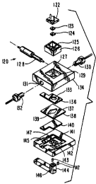
Figure 3A illustrates an exploded view of a flow cell 120 according to the
invention and Figure 3B illustrates a cross-sectional view of flow cell 120 as
assembled. Flow cell 120 comprises a light detector 122, an optical filter
123, a
15 conductive window 124, a shield 126, a reference electrode 128, couplings
130 and
132, a cell component 134, a counter electrode 136, a gasket 138, a working
electrode
140, a cell base 142, a pivot arm 144, magnet 146 and a magnet detector 147.
Light detector 122 is a sensitive light detection device, such as a
semiconductor photodetector, which is tolerant of relatively high temperatures
and
can operate accurately in the presence of a magnetic field. Preferably, light
detector
122 is sensitive to light in the 400-800 nm range, is physically small, e.g.,
1"xl"x.5"
or less, and comprises a silicon photodiode. In particular, IR-suppressing
photodiode
model #S 1227-66BR, manufactured by Hamamatsu, is a preferred implementation
of
light detector 122. It is further preferred that light detector 122 be
operable at
ordinary electronic device voltages, e.g., within the approximate range of +/-
12v, and
not utilize the high voltages required by devices such as a photomultiplier
tube, e.g.,
greater than +/- 24 volts.
Light detector 122 may optionally include an optical filter as an integral
component such as, for example, a thin film deposited on the light-collecting
surface
of detector 122. In particular, Hamamatsu's IR-suppressing photodiode model
#S 1227-66BR is considerably less sensitive to light of a wavelength greater
than
approximately 730 nm and, accordingly, demonstrates significantly improved
CA 02331490 2000-11-09
WO 99/58962 PCT/US99/10279
16
accuracy and precision in detecting light emitted by ECL labels comprising
derivatives of ruthenium Iris-bipyridyl (Ru(bpy)3). Accordingly, an IR-
suppressing
light detector 122, e.g., one that inherently avoids the detection of infrared
radiation,
is preferred. Light detector 122 produces a light measurement signal as a
function of
the light incident upon it.
Optical filter 123 transmits light of certain wavelengths to light detector
122
while substantially preventing the transmittance of light of other
wavelengths.
Preferably, optical filter 123 comprises a thin film of optically filtering
material that is
coextensive with a Iight detecting area of light detector 122. Alternatively,
filter 123
may comprise any optical component capable of passing certain wavelengths of
light
to light detector 122 and preventing other wavelengths of light from reaching
light
detector 122. As a further alternative, optical filter 123 may not be
coextensive with
light detector 122.
To maximize the operating efficiency of light detector 122, the transmittance
1 S characteristics of filter 123 are preferably matched to the wavelengths of
the light
emitted by an ECL label during an ECL assay. It is specifically preferred that
filter
123 absorb light having a longer wavelength than that of the light emitted by
the ECL
label. Preferred embodiments of filter 123 include one or more of i) a short
pass
filter having a transmittance of 600 nm light that is more than four times
greater than
its transmittance of 1000 nm light; ii) a short pass filter having a
transmittance of 600
nm light that is more than four times greater than its transmittance of 800 nm
light;
and iii) a short pass filter having a transmittance of 600 nm light that is
more than four
times greater than its transmittance of 700 nm light, or a combination
thereof.
Optionally, filter 123 may be omitted from flow cell 120. Alternatively,
filter 123
may be a short pass optical filter for passing light having a wavelength of
less than
800 nm, more preferably less than 750 nm, and most preferably less than 700
nm. In
addition, it is especially advantageous that filter 123 be adapted to detect
ECL
induced in Ru(bpy)3 and derivatives thereof.
In an alternate embodiment, light detector 122 comprises an avalanche
photodiode detector or an array of light detectors, such as a CCD array, CID
array, a
photodiode array, and the like. By utilizing an array of light detectors and
analyzing
CA 02331490 2000-11-09
WO 99/58962 PCT/US99/10279
17
their corresponding respective light detection signals, different sources of
light within
flow cell 120 may be differentiated from each other.
Conductive window 124 is formed of a thin, light-transmitting, electrically-
conductive material shaped to be coextensive with aperture 125. Alternatively,
conductive window 124 is not coextensive with aperture 125. Preferably, window
124 includes a metallic mesh comprising copper, brass, or the like.
Alternatively,
window 124 may comprise a transparent, conductive material such as a thin film
of
indium-tin oxide deposited on a transparent substrate. It is further
contemplated that
window 124 may comprise an electrically conductive or otherwise
electrostatically
shielding configuration of a solid, liquid, gel, or gas. Window 124 shields
light
detector 122 from electrical noise that might adversely affect its
performance; thus
window 124 is electrically shielded. The light transmittance of window 124
should be
greater than 40% and preferably is greater than 70%. It is most preferred that
window
124 have a transmittance of greater than 85% for light emitted by an ECL
label.
Where window 124 has been implemented as a mesh, it is preferred to size the
apertures in the mesh relative to the type of electromagnetic radiation
against which
the mesh is to shield. For example, meshes having apertures of less than 1 mm,
or
more preferably less than 0.7mm, or most preferably less than 0.3mm, have been
found to effectively shield against the apparent capacitive coupling between
light
detector 122 and one or more of working electrode 140 and counter electrode
136.
Shield 126 comprises a generally opaque configuration of electrically-
conductive material, such as brass, aluminum or the like, preferably shaped
like an
open container. Shield 126 has an open top to accommodate installation of
light
detector 122 and a bottom surface having an aperture 125 adapted to
accommodate
conductive window 124. Optionally, aperture 125 is adapted to additionally
accommodate optical filter 123. As a further option, shield 126 may include a
top
surface to thereby completely surround light detector 122. Alternatively,
shield I26
may comprise an electrically-conductive, and preferably transparent, coating
upon or
within light detector 122 and, thus, window 124 and/or shield 126 may
optionally be
omitted.
As a further alternative, shield 126 may be omitted if light detector 122 is
of a
type not adversely affected by capacitive interference or electric fields.
Shield 126
CA 02331490 2000-11-09
WO 99/58962 PCT/US99/10279
18
may have a bottom surface which both conducts electricity and transmits light
but
omits any aperture, e.g., has a continuous bottom surface. Of course, shield
126 and
conductive window 124 may be contiguous, e.g., a brass shield having a
perforated
bottom surface.
An optical epoxy, such as a mufti-part epoxy, may be used to bond together
light detector 122, filter 123, window 124, shield 126, and cell component 134
or any
subset thereof. Preferably, the optical epoxy fills in all the gaps, if any,
between the
elements, thereby ensuring an optional path between cell component 134 and
light
detector 122 which omits solid/air and liquid/air interfaces.
Couplings 130 and 132 are conventional fluid couplings for connecting fluid-
carrying tubes to cell component 134. Reference electrode 128 is an ECL
reference
electrode for detecting the voltage level of an assay sample. Preferably,
reference
electrode 128 includes a ceramic or glass frit along with an ionic transfer
medium,
and engages in only a minimal fluid transaction with the assay sample. It is
additionally preferred that electrode 128 be entirely replaceable and
modularly
renewable. The invention allows for increased lifetime of the ECL cell by
improved
design of the reference electrode. In one embodiment, the volume of the medium
in
the reference electrode is greater than 0.3 cubic inches. Alternatively, the
reference
electrode may be omitted.
Cell component 134 is comprised of a rigid material and is shaped to include a
central well 129, coupling opening 131 to accommodate coupling 132, another
coupling opening (not shown) to accommodate coupling 130, a reference
electrode
opening (not shown) to accommodate reference electrode 128, and a counter
electrode
groove (not shown) to accommodate counter electrode 136. As shown, the box-
shaped central well 129 is adapted to accommodate shield 126, window 124, and,
optionally, optical filter 123. Preferably, cell component 134 comprises a
durable,
transparent and chemically inert material such as plexiglass, acrylic,
polymethyl
methacrylate, or the like. Alternatively, component 134 may be comprised of a
non-transparent material except for at least some of its volume between its
lower
surface (which includes the counter electrode groove) and central well 129. At
minimum, base 127 of central well 129 should provide a transparent zone (e.g.,
an
optical pathway or window) between ECL chamber 139 and light detector 122
CA 02331490 2000-11-09
WO 99/58962 PCT/US99/10279
19
through which light generated in ECL chamber 139 may pass. Alternatively, base
127 may be omitted so that central well 129 forms an opening extending through
cell
component 134 and surfaces of light detector 122, optical filter 123, window
124
and/or shield 126 may define a portion of ECL chamber 139.
Counter electrode 136 comprises a conductive electrode having one or more
openings 133 therein. Opening 133 is preferably circular; but, may instead be
oval,
triangular, rectangular, diamond-shaped, trapezoidal or another shape.
Preferably,
counter electrode 136 is comprised of a metal, such as nickel, stainless
steel, gold or
platinum. Counter electrode 136 may comprise a mesh or a screen. Counter
electrode
136 is preferably shaped to fit a counter electrode groove in component 134
for secure
mounting. For example, counter electrode 136 may be "L"-shaped, as shown,
rectangular in shape, "T"-shaped or the like. The "L"-shape and "T"-shape are
particularly advantageous in that one "arm" of the configuration may be
positioned to
extend beyond the periphery of component 142 to provide an electrical contact
point
for the provision of electrical energy.
Gasket 138 comprises a conventional gasket material (e.g., silicone rubber)
which is preferably pliable and elastomeric so as to most effectively provide
fluid-
tight seals to the other surfaces that define ECL chamber 139. To reduce
lateral
deformation of the gasket during compression, gasket 138 is most preferably
formed
from a material with a durometer number of greater than 60 Shore A points
hardness.
By reducing lateral deformation, it is possible to maintain a more precise
control over
the lateral dimensions of ECL chamber 139 end thereby improve the precision of
ECL
measurements.
In an alternate embodiment, gasket 138 comprises an elastomeric material and
another material which has a greater lateral stiffness than the elastomer. For
example,
gasket 138 may be formed from a layered material comprising a laterally stiff
middle
layer, such as nylon or acrylic, that resists lateral deformation and a pair
of
elastomeric top and bottom layers that provide fluid-tight seals.
Additionally, the
middle layer could comprise a continuous solid, a network of fibers, or a
mesh. In a
gasket comprising a network of fibers or a mesh, the network or mesh is
preferably
oriented so that its longitudinal axis is substantially perpendicular to the
narrowest
dimension of the gasket.
CA 02331490 2000-11-09
WO 99/58962 PCT/US99/10279
Gasket 138 includes an opening 137 that is preferably shaped to allow an even
and uniform fluid flow through ECL chamber 139, especially over the surface of
working electrode 140. Preferred shapes for opening 137 include a
parallelogram and
a diamond with rounded corners. Opening 137 defines sides of ECL chamber 139.
5 Working electrode 140 comprises a conductive electrode, preferably made of a
metal, such as gold or platinum, formed in a planar sheet. Preferably,
electrode 140 is
shaped to fit within working electrode groove 143 for secure mounting therein.
For
example, electrode 140 may be "L"-shaped as shown, rectangular in shape, "T"-
shaped or the like. The "L"-shape and "T"-shape are particularly advantageous
in that
10 one "arm" of the configuration may be positioned to extend beyond the
periphery of
component 134 to provide an electrical contact point for the provision of
electrical
energy.
Cell base 142 comprises a rigid base material having an opening 145
extending therethrough, a working electrode groove 143 adapted to accommodate
15 working electrode 140, and a gasket groove 141 adapted to accommodate
gasket 138.
Preferably, cell base 142 comprises a durable and chemically inert material,
such as
plexiglass, acrylic, polymethyl methacrylate, or the like. As shown, opening
145
preferably has the cross-section of a square with rounded corners but,
alternatively,
may have any shape suitable to accommodate magnet 146 and/or pivot arm 144.
20 Optionally, opening 145 is omitted from cell base 142.
Preferably, magnet detector 147 extends into or near opening 145. In another
embodiment, magnet detector 147 is attached to the lower surface of base 142
or is
incorporated into base 142. Magnet detector 147 preferably comprises a
conventional
magnetic field detector such as a magnetometer and provides an output signal
indicating the presence, absence, or proximity of magnet 146 and/or pivot arm
144.
In an especially preferred embodiment, magnet detector 147 comprises one or
more
Hall-effect sensors or the like. Alternatively, magnet detector 147 is omitted
from
cell 120.
Cell component 134 and cell base 142 may be held together by a conventional
retaining device incorporated into, affixed to, or associated with one or both
of
component 134 and base 142. Such a retaining device may comprise screws,
rivets,
bolts, pins, clips, clamps, elastic fasteners, adhesives, tapes, fasteners,
and the like.
CA 02331490 2000-11-09
WO 99/58962 PCT/US99/10279
21
Preferably, working electrode 140 is mounted in working electrode groove
143 without any adhesive or permanent fastener. Instead, electrode 140 fits
precisely
within groove 143 and is held in place by gasket 138 sandwiched between cell
component 134 and cell base 142. As a result, working electrode 140 is readily
S removed and replaced. By avoiding the use of an adhesive or other fixing
agent to
secure electrode 140, the process for manufacturing cell 120 is simplified
considerably and the useful lifetime of cell 120 is substantially increased.
The
working electrode 140 is thus removably fitted into the cell. The cell of the
invention
can have a useful lifetime greater than 10,000 assay measurements; preferably
this
lifetime exceeds 25,000 assay measurements; more preferably, the lifetime of
the cell
exceeds 50,000 assay measurements; even more preferably, the lifetime exceeds
100,000 measurements; most preferably the lifetime of the cell exceeds
1,000,000
assay measurements.
Opening 137 in gasket 138, portions of working electrode 140 and counter
electrode 136, both defined by gasket 138, and a portion of cell component 134
provide the boundaries for ECL chamber 139. Together, these elements also
define a
fluid path through ECL cell i20. It should be appreciated that opening 137 is
positioned such that the fluid path does not include any seam between working
electrode 140 and cell base 142.
Magnet 146 is a conventional magnet device, preferably a permanent magnet
having a generally square shape, and is affixed to pivot arm 144.
Alternatively,
magnet 146 may comprise an electromagnet or the like. Pivot arm 144 is a
generally
rigid pivot arm configured to position magnet 146 within opening 145. At
opening
145, magnet 146 may removably be positioned to touch working electrode 140 or
may
be positioned near thereto.
As shown in Figure 3B, the registration of working electrode 140, opening
137, opening 133, transparent base 127, aperture 125, conductive window 124,
optical
filter 123 and light detector 122 is an important feature of the invention.
Proper
registration of these elements ensures optimal transmittance of light from the
vicinity
of working electrode 140 to light detector 122. Additionally, registration of
magnet
146 and opening 145 with working electrode 140 allows for the precise and
efficient
application of magnetic energy at working electrode 140. Such magnetic energy
is
CA 02331490 2000-11-09
WO 99/58962 PCTNS99/10279
22
used to attract magnetic particles from an assay sample to working electrode
140
where electrochemiluminescence may be induced. Preferably, opening 133 itself
functions as an optical element that defines the region of working electrode
140 and
ECL chamber 139 from which induced electrochemiluminescence may propagate to
light detector 122. Per design, counter electrode 136 may block undesired
light
generated in certain regions of ECL chamber i 39. Preferably, the size and
shape of
the counter electrode aperture 133 is designed to maximize collection of light
emitted
from those regions of the working electrode 140 where magnetic beads have been
deposited and minimize collection of light emitted from other regions of the
working
electrode 140.
Additionally, precise registration of opening 133 and magnet 146 is
particularly important to maximize the amount of luminescence attributable to
the
desired reaction (vs. luminescence attributable to ancillary reactions) that
is incident
upon light detector 122. The strength and shape of the magnetic field produced
by
magnet 146 defines the region in which any material attracted by the magnetic
field,
e.g., magnetic beads, comes to rest. Preferably, opening 133 is sized and
shaped to
allow light emitted by or near such materials collected by magnet 146 in the
vicinity
of working electrode 140 to reach light detector 122 while minimizing the
amount of
light generated in other regions that reaches light detector 122. Accordingly,
light
detector 122 should be sized relative to opening 133 (or vice versa) to ensure
that the
desired electrochemiluminescence is collected. Preferably the working area of
light
detector 122 is slightly larger than the cross sectional area of the light
cone generated
at the electrode and emitted through aperture 133.
Figures 4A, 4B, 4C, and 4D illustrate detailed views of cell component 134.
Figure 4A is a cross-sectional view of cell component 134 taken along the line
4A-4A
of Figure 4B. Figure 4B is a top view of cell component 134. Figure 4C is a
cross-
sectional view of cell component 134 taken along the line 4C-4C of Figure 4B.
Figure 4D is a bottom view of cell component 134.
Figure 4A illustrates a side cross-sectional view of cell component 134 and
particularly depicts a central well 129, coupling openings 180 and 131, fluid
ports 182
and 186, and a counter electrode groove 184. Central well 129 preferably has a
cross-
section compatible with that of light detector 122 and shield 126 (see Figure
3A), e.g.,
CA 02331490 2000-11-09
WO 99/58962 PCT/US99/10279
23
rectangular as shown, and has a depth of approximately 75% of the depth of
component 134. By embedding light detector 122 in central well 129, light
detector
122 is positioned in close proximity to ECL chamber 139 and working electrode
I40.
Such proximity facilitates efficient light detection. In preferred embodiments
of
assembled cell 120, the distance between light detector 122 and working
electrode
140 is less than 4.0 mm, or more preferably less than 2.2 mm. As shown, a
portion of
cell component I34 separates ECL chamber 139 from central wall 129; in a
preferred
embodiment, the thickness of this material is less than 2.0 mm, ~or more
preferably
less than 1.3 mm.
Since interfaces in an optical path between materials (e.g., a plastic/air
interface), interface between phases (e.g., a liquid/solid, solid/gas, or
liquid/gas) or
between materials with different refractive indices, may impede light
transmission,
cell 120 is designed to avoid or minimize such interfaces. In particular, the
optical
path between light detector 122 and ECL chamber 139 preferably avoids any
interfaces that includes air, e.g., an air gap. To provide optimal optical
coupling
among elements in the optical path between detector 122 and chamber 139,
optical
adhesives and epoxies, index matched liquids, and index matched compliant
materials, and the like are utilized to eliminate air gaps. Such optical
coupling
materials are especially useful in implementing a mesh as shield 124 (see
Figure 3A),
since the optical coupling materials displace gas existing in the interstitial
spaces
between elements of the mesh. The use of optical coupling materials to
eliminate air
gaps has improved optical efficiency by as much as 40%. In a preferred
embodiment,
all cell elements and optical coupling materials forming the optical path
between
detector 122 and chamber 139 have refractive indices between 1.3 and 1.6,
while
refractive indices between 1.45 and 1.55 are especially preferred.
The light collection efficiency of cell 120 is a function of several factors
such
as, i) the strength, shape and placement of magnet 146; ii) the size, shape
and position
of opening 133; iii) the transmittance of window 124; iv) the distance between
light
detector 122 and ECL chamber 139; v) the efficiency of optical coupling among
materials within the optical path; vi) the size and placement of light
detector 122; vii)
the properties of optical filter 123 and viii) cell geometry, e.g., the
alignment of and
distance between elements that comprise the optical path. Light collection
CA 02331490 2000-11-09
WO 99/58962 PCTNS99/10279
24
efficiencies greater than 35% is preferred; efficiency greater than 40% is
more
preferred; and efficiency greater than 50% is even more preferred.
Coupling opening 180 is adapted to receive coupling 130 and coupling
opening 131 is adapted to receive coupling 132. Counter electrode groove 184
is
adapted to receive counter electrode 136. A tube in component 134 connects
coupling
opening 180 and fluid port 182. Another tube in component 134 connects
coupling
opening 131 and fluid port 186. Fluid ports 182 and 186 are positioned to
allow fluid
to flow from one port to the other through the ECL chamber 139 defined by
opening
137 in gasket 138 (sides), working electrode 140 (bottom), counter electrode
135
(top), and circular hub 188 of cell component 134 (top). The longitudinal ends
of
opening 137 align with ports 182 and 186.
Figure 4B illustrates a top view of cell component 134 and particularly
depicts
central well 129. Central well 129 is adapted to receive shield 126 and
conductive
window 124.
Figure 4C illustrates a side cross-sectional view of cell component 134 and
particularly depicts a reference electrode opening 190. Opening 190 intersects
the
tube connecting coupling opening 180 and fluid port 182. Reference electrode
opening 190 is adapted to receive reference electrode 128.
Figure 4D illustrates a bottom view of cell component 134 and particularly
depicts counter electrode groove 184 and circular hub 188. The surface of
circular
hub 188 is preferably flat and flush with the bottom surface of cell component
134.
Hub 188 is preferably integral to component 134 and is adapted to fit exactly
within
opening 133 of counter electrode 136. Hub 188, along with that portion of
component
134 between hub 188 and central well 129 provide an optical pathway or window
through which light may travel.
Figure 5 illustrates an apparatus 200 incorporating an ECL measurement
module 226 according to an embodiment of the present invention. Module 226
comprises a main interface 210, a main controller 214, a heater 216, an
amplifier 218,
a flow cell 120, a magnet detector 220, a magnet controller 222, and a
temperature
controller 224. Also shown are a power source 202, a host interface 204, an
input
fluid source 208, and an outlet for waste 212. Module 226 is preferably housed
within a light-tight enclosure.
CA 02331490 2000-11-09
WO 99/58962 PCT/US99/10279
Main interface 210 is preferably the only interface for apparatus 210 and may
consist of multiple individual interfaces (e.g. connectors) suitable for
multiple
connections. Interface 210 preferably includes removable connections to power
source 202, host interface 204, input source 208, and outlet 212. Since such
5 connections are removable, module 226 may be easily replaced as a single
operational
module. In addition, the modular design of the apparatus 226 allows for its
incorporation into a variety of other instruments through connections to main
interface 210. Preferably, the multiple connectors of main interface 210 are
grouped
such that the connections may be engaged or disengaged together in a single
10 procedure. It is an important feature of this invention that the connectors
can be
engaged or disengaged readily, and in some embodiments, without fully
interrupting
the function of the device (e.g. "hot-swapping"). Preferably, fluid connectors
incorporated into main interface 210 are self sealing on disengagement and/or
self
opening on engagement to prevent leakage of fluid or fluid path obstruction.
15 Main controller 214 is a control device, such as microcontroller PIC 16C65
by
Microchip or the like, for controlling the basic operation of module 226 in
response to
commands from an external host (not shown). Main controller 214 is coupled to
main
interface 210, amplifier 218, flow cell 120, magnet detector 220, magnet
controller
222, and temperature controller 224. Alternatively, main controller 2i4 may
include
20 a waveform generator such as a voltage source, a current source, a power
supply, a
potentiostat, or the like. Preferably, such a waveform generator is
controllable and
may be externally controllable, e.g. by an external control device.
Preferably, such a
waveform generator may be controlled so as to generate waveforms of any shape,
including steps, ramps, ramp-and-holds, sinusoids, and/or any combination of
the
25 abovementioned waveforms. The waveform is optionally repeated multiple
times.
Upon receiving commands from an external host connected to host interface 204
through main interface 210, main controller 214 issues appropriate commands
to, and
may control the supply of power to, constituent parts of module 226.
Preferably main
controller 214 comprises a programmable timing controller, such as an electro-
mechanical control device and, alternatively, may comprise a microprocessor-
based
control system. Optionally, controller 214 comprises a storage device, such as
a
CA 02331490 2000-11-09
WO 99/58962 PCT/US99110279
26
semiconductor memory, magnetic storage media, optical storage media, magneto-
optical storage media, and the like.
Amplifier 218 is an amplifier with controllable gain for amplifying the light
measurement signal produced by light detector 122. Preferably, amplifier 218
has a
gain of between 1 and 8000. The light measurement signal produced by light
detector
122, a part of flow cell 120, may be amplified by amplifier 218 in accordance
with a
control signal provided by main controller 214. Optionally, the light
measurement
signal or an amplified version thereof is provided to main controller 2I4.
Amplifier
218 is preferably directly connected to the output of light detector 122.
Flow cell 120 is the flow cell of Figure 3 as previously described. Electrical
energy is provided to cell 120 by main controller 214. In particular, the
electrical
energy may be generated by a waveform generator included in main controller
214.
Magnet detector 220 detects the positioning of magnet 146 and, in particular,
whether magnet 146 is or is not proximate working electrode 140.
Alternatively,
magnet detector 220 may simply detect the positioning of pivot arm 144.
Detector
220 provides an output signal to main controller indicative of the position of
magnet
146. Magnet detector 220 may optionally be incorporated into flow cell 120.
Magnet
detector 220 is shown in Figure 3A as magnet detector 147.
Magnet controller 222 is a control device, responsive to operational control
signals from main controller 214 for controlling the positioning of magnet
146.
Preferably, magnet controller 222 is an electro-mechanical device for
positioning
pivot arm 144. It is fiuther preferred that proper operation of controller 222
and arm
144 are verified by reference to an output signal of magnet detector 220.
Heater 216, coupled to temperature controller 224, is a conventional
controlled
heating device for heating input fluid to be introduced into flow cell 120.
Temperature controller 224 is a conventional temperature controller for
controlling
the operation of heater 216 and responding to control signals from main
controller
214. Controller 224 receives power from power source 202 via main interface
210
and, preferably, controls the flow of power to heater 216. Controller 224 may
include
temperature sensors to determine the temperature of input fluids or,
alternatively, such
sensors may be incorporated into heater 216. Optionally, heater 216 and/or
temperature controller 224 may be omitted.
CA 02331490 2000-11-09
WO 99/5$962 PCT/US99/10279
27
In operation, fluid supplied from input fluid source 208 via main interface
210
may be heated by heater 216 and provided to an input of flow cell 120,
specifically
coupling 132. Coupling 132 transfers the input fluid through coupling opening
131 to
fluid port 186 and into ECL chamber 139. Main controller 214 controls magnet
controller 222 to position magnet 146 in proximity to working electrode 140.
Magnet
detector 220 provides a signal to main controller 214 indicative of the
positioning of
magnet 146.
Main controller 214 applies electrical energy to working electrode 140 and
counter electrode 136 to cause the input fluid to electrochemiluminesce.
Reference
electrode 128 detects a reference voltage in the input fluid and provides a
corresponding reference voltage signal to main controller 214. Main controller
214
adjusts its application of electrical energy to working electrode 140 and
counter
electrode 136 as a function of the reference voltage signal.
Light detector 122 detects the induced electrochemiluminescence and supplies
a light measurement signal to amplifier 218 for amplification. Amplifier 218
provides
the original or amplified signal to main controller 214 which routes same to
main
interface 210 for output to the host interface 204 and acquisition by the host
(not
shown).
The input fluid is pumped through ECL chamber 139 into fluid port 182 and
coupling 130 via coupling opening 180. The expelled fluid travels through main
interface 210 to outlet 212. Throughout the process, power source 202,
connected to
main interface 210, provides the power needed by module 226. Through main
interface 210 and host interface 204, main controller 214 may be controlled by
an
external host to process input sample fluids at specific temperatures, with
specific
patterns of electrical energy, and with or without the application of a
magnetic field.
Figure 6 provides a flow chart illustrating a preferred method 250 of ECL test
measurement according to an embodiment of the present invention. According to
method 250, in step 254, main controller 214 controls magnet controller 222 to
control pivot arm 144 to raise magnet 146 into a position in close proximity
to
working electrode 140. Magnet detector 220 detects the position of the magnet
to
verify its proper placement. In the next step 256, an assay sample is
transported to the
fluid entry port of the flow cell, e.g., fluid port 186, having already passed
through
CA 02331490 2000-11-09
WO 99/58962 PCT/US99/10279
28
main interface 210 and heater 216. Thereafter, in step 258, the assay sample
is
pumped through ECL chamber 139 and materials in the assay sample (e.g.,
magnetic
particles used as a solid phase support for binding assays) are collected by
the
magnetic field of magnet 146 at working electrode 140.
A washing fluid, such as an assay buffer, is then pumped through ECL
chamber 139 at a relatively high speed in step 260 to wash the materials
collected by
magnet 146. Thereafter, an assay fluid, such as an assay buffer, may be pumped
through ECL chamber 139 at a relatively low speed. In step 262, main
controller 214
controls light detector 122, possibly through amplifier 218, to detect a
background
level of light present in ECL chamber 139.
In the subsequent step 264, main controller 214 applies electricity to the
sample collected at working electrode 140. An electric field is created
between
counter electrode 136 and working electrode 140. To induce ruthenium tris-
bipyridyl
derivatives to electrochemiluminesce, the electric field is preferably
generated by
1 S stepping the potential at the working electrode to a predefined value
between 1.2-1.4
V (vs. Ag/AgCI) and holding such voltage for a predefined period of 1.5-2.0
seconds.
The collected sample is thereby induced to electrochemiluminesce and the
intensity of
the resulting light is measured by light detector 122. Detector 122 provides a
light
measurement signal to main controller 214 via amplifier 218. Main controller
214
may modulate the strength of the applied electric field.
The implementation of a light detector 122 that operates accurately in the
presence of a magnet field is clearly advantageous. The magnetic field
concentrates
sample materials.at the surface of working electrode 140 and prevents their
dispersion. With magnet 146 raised, ECL measurements may be made successfully
under conditions of moderate to strong fluid flow without loss of sample. In
addition,
by measuring ECL under conditions of flow, reagents consumed by the ECL
process
can be replenished during the measurement.
In step 266, main controller 214 controls magnet controller 222 to cause pivot
arm 144 to be retracted, lowering magnet 144 away from working electrode 140.
Thereafter, in step 268, a cleaning and/or conditioning cycle occurs.
Preferably,
cleaning fluid and/or air bubbles are pumped through the flow cell during the
cleaning
cycle.
CA 02331490 2000-11-09
WO 99/58962 PCT/US99/1OZ79
29
Optionally, a second magnet (not shown) can be used to aid in the removal of
magnetic material on the working electrode during the cleaning cycle. This
second
magnet may be located above or adjacent to light detector 122 to apply a
magnetic
field at or near the surface of working electrode 140 to influence particles
at or near
the surface of the electrode. Preferably, the second magnet produces a weaker
field
than magnet 146 such that when magnet 146 is adjacent working electrode 140,
the
weaker field does not interfere with the concentration of magnetic sample
materials at
the electrode. Alternatively, the second magnet is an electromagnet that is
not
powered while magnet 146 is adjacent working electrode 140. As a further
alternative, the second magnet is a movable magnet that can be moved away from
working electrode 140 when magnet 146 is adjacent thereto.
In the apparatus of the present invention, a magnet detector, e.g., a Hall-
sensor, independently verifies the consistencies of the magnetic field applied
to fluid
within ECL chamber 139. Accordingly, magnetic beads need not be used to
calibrate
this apparatus. ECL labels dissolved in solution or otherwise not affiliated
with
materials influenced by a magnetic field can be used as standards to measure
the
ability of cell 120 to induce and detect electrochemiluminescence
independently of
the magnetic field. Since magnetic bead-based calibration standards with well-
defined characteristics are difficult and expensive to manufacture reliably
and may be
unstable during long-term storage, it is advantageous that cell 120 may be
calibrated
without the utilization of such standards. Independent verification of the
magnetic
field with a magnet detector and utilization of an ECL standard not based on
magnetic
beads facilitates diagnostic methods that distinguish between magnetic field
failure
and electrochemiluminescence induction/detection failures. Such diagnostic
precision
considerably simplifies service and repair of an instrument.
In an alternate embodiment of apparatus 200, the temperature of fluid in flow
cell 120 is controlled very efficiently by applying heat energy to (or
removing heat
energy from) one or more surfaces of ECL chamber 139. Heater 216 may be
thermally coupled directly to a surface of ECL chamber 139, most preferably to
working electrode 140 which, preferably, has a high thermal conductivity.
Working
electrode 140 and the adjacent fluid may be quickly heated or cooled to reach
a
desired temperature in a matter of seconds, preferably 3 seconds or less.
Heater 216
CA 02331490 2000-11-09
WO 99158962 PCT/US99/10279
may be used to maintain the temperature of the electrode and adjacent fluid
constant
during an ECL measurement or to vary the temperature in a predetermined
manner.
However, since the temperature may be quickly adjusted, continuous temperature
control may not be needed during idle periods or during periods of a
measurement
5 cycle when precise temperature control is not necessary, if any. In
addition, since
ECL labels are induced to electrochemiluminesce at or near the working
electrode,
and the process for preparing a sample, inducing electrochemiluminescence and
removing a sample are often temperature sensitive, precise control of the
temperature
of the working electrode and of the fluid near the working electrode can
substantially
10 affect, and especially improve, overall performance and increase system
flexibility.
By directly heating fluid and surfaces that will be involved in an ECL
reaction and by
heating immediately prior to and/or during an ECL measurement, this heating
method
requires less power and can be implemented with a smaller and/or less
expensive
instrument as compared to heating methods that require continuous temperature
15 control of an entire flow cell and/or all fluids entering the flow cell.
The system is
also less sensitive to the temperature of entering sample and reagent fluids
and can be
used in a wider range of ambient temperatures than conventional ECL systems.
In one illustrative example, heater 216 is a thin flexible heating element
comprising a resistive element (e.g., an etched foil) laminated between layers
of
20 insulation (e.g., Kapton, Nomex, silicone rubber or mica). A suitable
resistive heating
element is a Kapton Thermofoil heater from MINCO Products, Inc. Thin heating
elements having thicknesses of less than 0.02", or preferably, less than 0.01
", can be
attached to working electrode 140, preferably at a location in registration
with ECL
chamber 139 but on the opposite side of the electrode. Even if the heating
elements
25 are positioned directly between magnet 146 and electrode 140, the elements
preferably do not significantly affect the capture of magnetic particles by
magnet 146
on the surface of working electrode 140 defining a portion of ECL chamber 139.
It is
particularly advantageous that heater 216 have a thin cross-section so that
magnet 146
will not be prevented from being positioned in close proximity to working
electrode
30 140. Heater 216 is, alternatively, a device for adding or removing heat
such as a
Peltier device. Such a heater 216 adds or removes heat to adjust the
temperature of
the working electrode and adjacent fluid as desired, prefereably independent
of the
CA 02331490 2000-11-09
WO 99/58962 PCT/US99/10279
31
temperature of the fluid entering the ECL module and the heat generated during
the
induction of ECL. Alternatively, heater 216 is a resistive heater, sonic
heater, or
infrared heater.
Heater 216 is preferably coupled to working electrode 140 with an adhesive or
thermally conductive grease. Nonuniform heat transmission from heater 216 may
be
tolerable since the working electrode (e.g., platinum) has a high thermal
diffusivity,
thereby ensuring that the temperature distribution throughout the electrode,
particularly on the side exposed to fluid, is uniform.
Temperature controller 224 may comprise a temperature sensor for measuring
the temperature of working electrode 140. Preferably, the temperature sensor
is a thin
film temperature sensor such as a resistance temperature detector (RTD).
Alternatively, the temperature sensor includes one or more thermometers,
thenmisters,
thermocouples and infrared detectors. Preferably, the temperature sensor is
attached
to working electrode 140 at a location on the working electrode adjacent to
the
I 5 location where heater 216 is attached. Alternatively, the heating element
of heater
216 has an aperture and the temperature sensor is attached to the working
electrode
through the aperture in the heating element. The temperature sensor is
preferably an
ultraminiature platinum thin film RTD sensor such as part number S245PD12 from
MINCO Products, Inc. Due to the high thermal diffusivity of working electrode
140,
the exact point of attachment of the temperature sensor to or near to the
working
electrode should not be critical. Preferably, the sensor is located outside
the region of
working electrode 140 in registration with magnet 146.
The temperature sensor may also be an integral component of heater 216 or
may be a source of heat itself. For example, a temperature sensor in
temperature
controller 224 may measure the temperature of working electrode 140 by
monitoring
the temperature-dependent change in the resistance of a resistive heating
element in
heater 216. An example of a temperature controller that works by this method
is the
Heaterstat Sensorless Temperature Controller from MINCO Products.
In operation, heater 216, coupled directly to the surface of working electrode
140 opposite ECL chamber 139, is, preferably, not heating or cooling the
electrode
during the cleaning, sample transport and washing phases of a measurement
cycle, as
well as during idle periods when the instrument is not in use. Just prior to
applying
CA 02331490 2000-11-09
WO 99/58962 PCT/US99/10279
32
electricity to the working electrode to induce ECL at or near the electrode
(the ECL
induction phase), the flow of fluid through flow cell 120 is reduced,
preferably to
zero, and temperature controller 224 controls heater 216 to adjust the
temperature of
working electrode 140 to reach and maintain a desired temperature (the
preheating
phase). Alternatively, fluid flow continues during both the preheating phase
and the
ECL induction phase and temperature controller 224 controls heater 216 to
adjust the
temperature of working electrode 140 and a layer of the fluid near thereto. As
a
further alternative, heater 216 does heat and/or cool the electrode during the
cleaning,
sample transport, and washing phases of a measurement cycle. Temperature
controller 224 measures the initial temperature of the electrode and
calculates the
heating power curve required to reach and maintain the desired temperature
(open
loop mode) or, alternatively, monitors the temperature of the working
electrode and
controls heater 216 to maintain the desired temperature (closed loop mode).
In one embodiment, heater 216 is operative during the preheating phase and
remains operative during the ECL induction phase. In this case, all of the
fluid in
ECL chamber 139 need not reach thermal equilibrium; instead, it is preferred
that the
fluid that diffuses to working electrode 140 during the course of the ECL
induction
phase be maintained at the desired temperature. Since heat diffuses in water
(thermal
diffusivity ~ 1.4 x 10'' m2/s) approximately 100 times faster than small
molecules
diffuse in water (diffusion coefficient ~ 1.5 x 10'9 m2/s), changes in
temperature
propagate faster in water than changes in concentration. For this reason, it
may be
only necessary to preheat to the desired temperature the heater itself, the
working
electrode, and a very thin layer of fluid above the working electrode.
Therefore, the
preheating times may be kept relatively short (typically 0.1-3.0 sec.).
Preferably,
temperature controller 224 controls heater 216 to maintain working electrode
140 at
the desired temperature during the course of the ECL induction phase and de-
energizes heater 216, allowing the temperature to vary, when the ECL induction
phase
is complete.
In an alternate embodiment, heater 216 is operative during the preheating
phase, but not during the ECL induction phase. In this case, all of the fluid
in ECL
chamber 139 need not reach thermal equilibrium; rather, it is preferred that
only
enough of the fluid in ECL chamber 139 is heated such that the temperature at
CA 02331490 2000-11-09
WO 99/58962 PCTNS99/10279
33
working electrode 140 remains relatively constant during the ECL induction
phase,
despite the lack of active temperature adjustment during that phase.
Generally, more
preheating is needed when heater 216 is not active during the ECL induction
phase;
however, the preheating times are still relatively short (typically, 0.5-3.0
sec.).
The invention includes integrated systems for measuring analytes. These
systems include one or more integrated ECLM modules as described above. The
system may include a sample introduction device, power supplies, controllers,
and
electrical mechanical and fluid connections to the modules, a case or physical
support
and a user interface. The sample introduction device, power supplies,
controllers, and
electrical mechanical and fluid connections to the modules, a case or physical
support
and user interface may or may not be shared by a plurality of ECL modules. The
ECL
modules in these systems are designed to be integrated with other
instrumentation that
generates samples benefiting from diagnostic testing (e.g. chemical reaction
chambers, bioreactors, biomolecule synthesizers, water collection systems,
lithographic processors) without undue effort, cost or expenditure of time.
Figure 7 illustrates an assay system 400 with multiple ECL modules 408A-D.
System 400 includes a sample source 402, a reagent source 404, a fluid
distribution
network 406, ECL modules 408A-D, waste repository 410, controller 412, and
power
supply 414. As shown, fluid distribution network 406 is coupled to each of
sample
source 402, reagent source 404, ECL modules 408A-D, controller 412 and power
supply 414. ECL modules 408A-D are each further coupled to waste repository
410,
controller 412 and power supply 414. All connections to ECL modules 408A-D,
besides physical supportive connections (not shown), occur through the
respective
main interface 210 (Fig. 5) of each. System 400 in whole, or in part, may be
enclosed
within a temperature-controlled environment. In an alternative embodiment,
assay
system 400 includes a single ECL module 408A, thus omitting ECL modules 408A,
4088 and 408C. System 400 can be configured to accommodate any number of ECL
modules 408. In hand-held or portable versions of system 400 power supply 414
may
comprise a battery, fuel cell, one or more solar panels, or the like.
Sample source 402 comprises a conventional device for providing one or more
assay samples. For example, source 402 may include one or more sample probes,
pipettes, pumps, valves, tubing, containers for samples, meters, flow control
devices,
CA 02331490 2000-11-09
WO 99/58962 PCT/US99110279
34
sample preparation devices, sample processing devices and other apparatus, or
a
combination thereof. Such sample processing devices may include filters,
mixing
chambers, reaction chambers and the like. Source 402 may also include, for
example,
multi-well plates, cartridges, test tubes and vacuum blood draw tubes. A
cartridge
S may include a filtration membrane for filtering blood and may also contain
other
analytical components (e.g. ion selective electrodes, oxygen electrodes).
Source 402
may comprise a system for handling and/or moving sample containers, e.g.,
multi-
well plate stacking devices, tube carousels or racks, and automated sample
delivery
systems such as conveyer belts and robotic systems. Source 402 may include
identification (e.g. bar codes or magnetic strips) devices to identify
samples. In
addition, source 402 may comprise, e.g., a separation device, such as a
chromatography instrument or an electrophoresis instrument. Still further,
source 402
may include a network of analytical devices, such as a chemical reactor, a
protein
sequencer, a separation device, a bioreactor, a chemical analysis instrument,
or the
like. Control of such systems may be implemented through controller 412 via a
connection (not shown) or by another control device (not shown).
In an alternate embodiment, source 402 is the output stream of another
analytical device, e.g., a device for the separation of materials, such as an
HPLC or
other chromatographic systems, a chemical reaction chamber, a cell culture
chamber,
a device for identifying and/or synthesizing chemicals or biological
materials, such as
a spectrometer, a fluorometer, a protein or nucleic acid sequencer or a
synthesizer.
Alternatively, source 402 may include an integrated system for processing
samples
containing nucleic acids and/or for amplifying nucleic acids. This system may
include apparatus for processes such as polymerase chain reaction (PCR),
nucleic acid
sequence-based amplification (NASBA), ligase chain reaction (LCR), strand
displacement amplification (SDA), transcription mediated amplification (TMA),
amplification through generation of branched chains, and the like. Source 402
may
comprise the flow PCR amplification devices described in U.S. Patent Nos.
5,716,842
and 5,270,183, hereby incorporated by reference.
Reagent source 404 comprises a conventional device for providing one or
more reagents, such as ECL coreactant, binding reagents, ECL label, a
suspension of
magnetic beads, and the like. For example, source 404 may include one or more
CA 02331490 2000-11-09
WO 99/58962 PC'r/US99/10279
pumps, valves, tubing, containers for reagents, reagent identification devices
(e.g. bar
codes or magnetic strips), meters, flow control devices and reagent
preparation
devices, or a combination thereof.
Fluid distribution network 406 routes samples) from sample source 402 and
S reagents) from reagent source 404 to one or more of ECL modules 408A-D.
Network 406 may comprise one or more sample probes, pipettes, pumps, valves,
tubing, meters, flow control devices, sample preparation devices, and
processing
devices, or a combination thereof. Such processing devices may include
filters,
mixing chambers, reaction chambers and the like. Preferably, network 406 is
10 controlled by controller 412 and powered by power supply 414.
Alternatively,
network 406 is manually controlled.
In an alternate embodiment, sample source 402 and/or reagent source 404
comprise individual removable cartridges containing sample andlor reagent.
Correspondingly, fluid distribution network 406 comprises a cartridge
receptacle for
15 receiving a sample source 402 cartridge and/or a reagent source 404
cartridge.
Alternatively, sample source 402, waste repository 410, and/or reagent source
404 are
included in a single removable cartridge. The individual removable cartridges
may
include processing devices such as filters, mixing chambers, reaction chambers
and
the like. Such cartridges may contain a plurality of separate compartments for
20 containing a plurality of samples, reagents, andlor waste fluids. These
compartments
may be individually accessed by fluid distribution network 406 through the use
of a
sample probe or through fluidics and fluidic connectors integral to the
cartridge. The
individual cartridges may also include internal or external standards for the
calibration
and/or validation of assays. In addition, the individual removable cartridges
may also
25 include one or more sample probe wash chambers containing wash solutions
for
cleaning a probe used to introduce samples or reagents into fluid distribution
network
406.
One embodiment of system 400 of the invention is a device for conducting
assays in mufti-well (e.g. 96-well and 384-well) plates. Sample source 402 is
a multi-
30 well plate {e.g. a standard format 96 well or 384 well plate) that may
include
identification (e.g. bar codes or magnetic strips). Reagent source 404 is one
or more
containers that may include identification (e.g. bar codes or magnetic
strips). Fluid
CA 02331490 2000-11-09
WO 99/58962 PCT/US99/10279
36
distribution network 406 includes fluid connections to source 404, 1-12 fluid
probes
for sampling fluid from multi-well plates, valves, pumps, and tubing, and
devices for
controlling the temperature of fluids (e.g. heaters). This embodiment includes
between 1 and 12 ECL measuring modules 408 as described in Figure S (see
descriptions of modules 408A-D below). Waste 410 is a conventional device for
handling waste and may comprise a fluid line to a drain, a waste bottle, or an
absorbent pad. Waste repository 410 may be a well or chamber within a
removable
cartridge; such a cartridge may also comprise sample source 402 and/or reagent
source 404. Waste 410 may include reagents for neutralizing chemicals, for
sterilizing biomaterials, or for neutralizing, inactivating, or detoxifying
chemicals or
other reagents. Power supply 414 is a conventional power supply. Controller
412
may incorporate a central processing unit, a keypad, a display screen, status
indicators, data storage devices, software for instrument control and data
analysis,
devices that monitor the presence and placement of the mufti-well plates,
devices for
identifying reagents, samples and mufti-well plates (e.g. bar code readers,
magnetic
strip readers, modems), printing devices, network interface hardware and
software
(e.g. a network card or modem), keyboards and a mouse.
In operation, controller 412 identifies samples and reagents through use of
identification devices and ensures that mufti-well-plates 402 are correctly
positioned.
Controller 412 instructs fluid distribution network 406 to use fluid probes to
obtain
samples from mufti-well plates 402 and to distribute the samples to ECL
measurement
modules 408. Controller 412 also instructs fluid distribution network 406 to
distribute
reagents from reagent source 404 and to deliver these reagents to ECL
measurement
modules 408. In a preferred embodiment, eight fluid probes are used to sample
one
column of wells in a 96-well plate; these samples are then distributed through
fluid
distribution network 406 to eight ECL measurement modules 408. Controller 412
instructs ECL modules 408 to conduct ECL measurements; controller 412 receives
data from ECL modules 408, processes and analyses the data, and when
appropriate,
displays and stores the data.
ECL modules 408A, 408B, 408C, and 408D are independent ECL modules. A
preferred embodiment of such an ECL module has been described above in
connection with Figure 5. Specifically, ECL modules 408A-D should each include
CA 02331490 2000-11-09
WO 99/58962 PCTNS99/10279
37
main interface 210, main controller 214, heater 216, amplifier 218, flow cell
120,
magnet detector 220, magnet controller 222, and temperature controller 224. In
an
alternate embodiment, ECL modules 408A-D include only main interface 210, main
controller 214, flow cell 120, magnet detector 220, magnet controller 222, and
temperature controller 224. Optionally, magnet detector 220 and/or magnet
controller
222 may be omitted. In another alternate embodiment, ECL modules 408A-D
include
only main interface 210, main controller 214 and flow cell 120.
Although ECL modules 408A-D are shown coupled to controller 412 and
power supply 414 in parallel, such parallel connections may be replaced by a
serial
connection among ECL modules 408A-D, controller 412, and power supply 414.
Waste repository 410 is a conventional waste receiving device or system and
may include a combination of pumps, valves, tubing, containers for waste,
meters and
flow control devices. Waste repository 410 may be a well or chamber within a
removable cartridge; such a cartridge may also comprise sample source 402
and/or
reagent source 404. Alternatively, waste repository 410 may be omitted. In
this
embodiment, fluidic distribution network 406 is adapted to reverse the flow of
fluids
through ECL modules 408A-D so as to aspirate or otherwise flow waste fluids
back
through fluidic distribution network 406 and, preferably, into waste receivers
in
sample source 402 and/or reagent source 404.
Controller 412 is a control device for controlling the operation of fluid
distribution network 406 and ECL modules 408A-D. Controller 412 may comprise a
microcontroller or a microprocessor-based control system. Alternatively,
controller
412 may include a device for storing ECL data and may utilize data analysis
software
to analyze and display data from ongoing ECL measurements. Optionally,
controller
412 comprises a storage device, such as a semiconductor memory, magnetic
storage
media, optical storage media, magneto-optical storage media, and the like.
Controller
412 may include devices for identification of samples and reagents (e.g. bar
code
readers or magnetic strip readers). Additionally, controller 412 may be
integrated
with a network or central computing system that stores data, reconciles
records or
performs accounting or billing functions or yet other functions. Optionally,
controller
412 is adapted for remote communication with other computer systems. It is
preferred that controller 412 communicate with other components of system 400
CA 02331490 2000-11-09
WO 99/589b2 PCTNS99/1OZ79
38
through standard data transmission protocols such as RS-232 or I2C. Controller
412
may utilize serial or parallel communication protocols in communicating with
ECL
modules 408A-D.
Controller 412 may be integrated with other instruments used in the medical
environment, e.g. patient monitoring systems that include ECG, respiration
monitors,
temperature monitors, blood pressure monitors, blood chemistry analyzers,
oxygen
monitors and the like. Controller 412 may be integrated with other devices in
the
same physical housing or may be integrated through a networked connection.
In a further embodiment, controller 412 includes a user interface through
which a user may control the operation of system 400. Such interface may
include an
input device, such as a keypad or a touch screen as well as an output device,
such as a
display or a printer. Through the user interface, controller 412 may display
ECL
measurement data, analysis of such data, and information regarding the
performance
and operational characteristics of system 400.
Power supply 414 is a conventional power supply unit. Although shown
directly connected to each of fluid distribution network 406 and ECL modules
408A-
D, such connections may be omitted if power supply 414 is coupled to
controller 412
which may itself route power to each of fluid distribution network 406, and
ECL
modules 408A-D.
It is desired that ECL signals reported by different ECL modules 408A-D to
controller 412 be directly comparable to one another. Since slight variations
in the
operational characteristics of each ECL module may affect the ability of the
particular
module to induce and detect electrochemiluminescence, the invention provides
apparatus and methodology for calibrating and/or normalizing the operation of
multiple ECL modules. According to this procedure, each ECL module is tested
with
a set of reference samples to generate respective sets of measured values. One
of the
ECL modules may be designated the reference module and its measured values
designated as reference values. Alternatively, a reference ECL module may be
tested
with the set of reference samples to produce reference values. From the
measured
values and the reference values, controller 412 or an external
calibration/normalization device calculates for each ECL module a correction
transform function such that when the correction transform function is applied
to the
CA 02331490 2000-11-09
WO 99/58962 PCT/US99/10279
39
measured values, values approaching the reference values are produced. In the
simplest case, each ECL module is normalized so that when supplied with a
certain
reference sample the module will output the same reference signal (SR).
Preferably, the correction transform function is generated within an ECL
module, or provided thereto by controller 412 or by an external device. Such
correction transform function may be implemented within an ECL module by
adjusting the amplification gain applied to the light detector signal (SD), so
that the
amplified light detector signal (S,~) produced when the reference sample is
tested
equals SR. Alteinatively, correction may be carried out by calculating a
correction
transform function F~ = f(SR,SAR) and applying the correction transform
function to
further amplified light detector signals (SA) such that the output signal (So)
of the
ECL module is So = F~(SA). Preferably, F~ or the parameters of the correction
transform function is stored in a memory within the particular ECL module and
correction is implemented by the microcontroller internal to that module.
Following
calibration/normalization, the ECL modules should be completely
interchangeable
and comparable. In an alternate method, correction is achieved by a computer
or
microcontroller external to the ECL module, such as controller 412. Controller
412
may store in its memory an F~ for each ECL module it controls.
Through individual main interfaces 210, each of ECL modules 408A-D are
coupled to other components of system 400. Accordingly, individual ECL modules
are conveniently removed and replaced.
Optionally, ECL modules 408A-D share a common light detection device
provided in controller 412 and are optically coupled thereto via an optical
connector
such as a fiber optic line.
In operation, fluid distribution network 406, under the control of controller
412, retrieves one or more samples from sample source 402 and, optionally, one
or
more reagents from reagent source 404. Power supply supplies necessary power
to
network 406, ECL modules 408A-D, and controller 412. The samples) and
reagents) are distributed to one or more of ECL modules 408A-D. Controller 412
controls each of ECL modules 408A-D to conduct at least one ECL assay upon the
sample(s), utilizing selected reagent(s). Results from the ECL assays are
provided to
controller 412. Controller 412 controls fluid distribution network 406 to draw
CA 02331490 2000-11-09
WO 99/58962 PCTNS99/i OZ79
additional samples) and/or reagents) from sources 402 and 404, respectively,
and
provide same to particular ECL modules as the ECL assays are completed. The
additional fluid displaces the assayed materials which are flushed to waste
repository
410. Alternatively, waste repository 410 may be omitted. In this embodiment,
fluidic
S distribution network 406 is adapted to reverse the flow of fluids through
ECL
modules 408 A-D so as to aspirate or otherwise flow waste fluids back through
fluidic
distribution network 406 and, preferably, into waste receivers in sample
source 402
and/or reagent source 404.
Figures 8A and 8B illustrate external views of certain components of system
10 400. In Figure 8A, an ECL module 408A is shown comprising an enclosure
448A, a
pair of rails 450A, fluid connectors 452A and 456A, and electrical connector
454A. It
is preferred that all of ECL modules 408A-D have the same external features
and
elements as shown in Figure 8A. For point of reference, it should be
understood that
fluid connectors 452A and 456A together with electrical connector 454A
comprise a
15 main interface 210, as discussed above.
Enclosure 448A is a rigid enclosure for containing the components of ECL
module 408A and is preferably light-tight, thermally-insulated, and
electrically
conductive to shield the components of the ECL module from external
environmental
variations. ECL module 408A has a volume less than 50 cubic inches; preferably
it
20 has volume less than 25 cubic inches. A pair of rails 450A are attached to
enclosure
448A for mechanical engagement with complementary structures in chassis 458 of
system 400 (shown in Figure 8B). Rails 450A may be integral to enclosure 448A.
Alternatively, rails 450A could be replaced with another mechanical engagement
device for securely connecting ECL module 408A and chassis 458.
25 Fluid connectors 452A and 456A provide connections for fluid input to and
output from ECL module 408A. For example, fluid connector 452A may connect to
heater 216, or directly to flow cell 120, of module 408A. Similarly, fluid
connector
456A may connect to the fluid output of flow cell 120. Electrical connector
454A
provides a connection for power, data, and control signals. Preferably,
electrical
30 connector 454A includes a printed circuit board connector. Power
connections in
connector 454A may connect directly to main controller 214 and temperature
controller 224 of module 408A. Data and control signal connections in
connector
CA 02331490 2000-11-09
WO 99/58962 PCT/US99/10279
41
454A may connect directly to main controller 214.
In Figure 8B, a chassis 458 of system 400 is illustrated. Chassis 458, a rigid
enclosure for containing the components of system 400, includes a number of
module
receptacles 460A-D. Optionally, chassis 458 may be insulated and include a
heater or
a conventional temperature controller. Module receptacle 460A includes grooves
462A, fluid connectors 464A and 468B, and electrical connector 466A. As shown,
module receptacles 460A-D have the same features and include the same
elements.
Grooves 462A are adapted for complementary engagement with rails 450A of
enclosure 448A. Grooves 462A may comprise separate structures attached to
chassis
458A. Preferably, rails 450A and grooves 462A provide a facile, secure, yet
removable structural connection between ECL module 408A and chassis 458. Rails
450 and grooves 462A should be arranged to minimize the potential for damage
to
connectors 452A, 454A, and 456A of module 408A during insertion of module 408A
into chassis 458 and to prevent misaligned insertion. Removable coupling of
the ECL
modules to chassis 458 is preferred to allow for quick and easy replacement of
the
modules. Of course, many conventional configurations of mechanical engagement
structures and mechanisms may be substituted for rails 450 and grooves 462A.
Preferably, the mechanical fluid and electrical connections are engaged or
disengaged
together in one operation. It is an important feature of this invention that
the
connectors can be engaged or disengaged readily, and in some embodiments,
without
fully interrupting the function of the device (e.g. "hot-swapping").
Fluid connectors 464A and 468A provide connections fox fluid exchange with
system 400. Preferably, fluid connector 464A is connectable to fluid connector
456A
and itself connects to waste repository 410. Fluid output from a flow cell 120
is thus
routed to waste repository 410. Fluid connector 468A is preferably connectable
to
fluid connector 452A and itself connects to fluid distribution network 406.
Samples)
and/or reagents) are distributed by fluid distribution network 406 via
connectors
468A and 452A to heater 216 or flow cell 120. Electrical connector 466A is
connectable to electrical connector 454 and itself connects to controller 412
and/or
power supply 414. It is preferred that the fluid and electrical connections be
made
simply by sliding an ECL module into one of module receptacles 460A-D.
Preferably,
fluid connectors 452A, 456A, 464A and 468A are self sealing on disengagement
CA 02331490 2000-11-09
WO 99/58962 PCT/US99/10279
42
and/or self opening on engagement to prevent leakage of fluid or fluid path
obstruction. In an alternate embodiment, fluid connector 464A, fluid connector
456A
and waste repository 410 may be omitted. In this embodiment, fluidic
distribution
network 406 is adapted to reverse the flow of fluids through one or more of
ECL
modules 408A-D so as to aspirate or otherwise flow waste fluids back through
fluidic
distribution network 406 (via respective connectors 468A-D and 452A-D) and,
preferably, into waste receivers in sample source 402 and/or reagent source
404.
System 400 is adapted for integration into diagnostic devices for performing
large numbers of chemical or biochemical analyses at very high speeds
(although its
low cost and simplicity also make it useful for low-throughput assay systems
such as
might be found in a small research laboratory or a doctor's office). A high
volume of
diagnostic tests can be performed by operating a plurality of ECL modules in
parallel.
By carrying out multiple ECL assays simultaneously, overall assay throughput
can be
dramatically increased. In one embodiment, more than 1 SO assay measurements
are
conducted in one hour. In a preferred embodiment, more than S00 assay
measurements are conducted in one hour. In a more preferred embodiment, more
than 750 assay measurements are conducted in one hour. In a still more
preferred
embodiment, more than 10,000 assay measurements are conducted in one hour. On
a
system-wide basis, coordination of the ECL modules and processing of data
therefrom
may be accelerated by utilizing parallel connections to the ECL modules for
the
transmission of control and data signals. However, in certain applications
serial
connections of control and data signals among ECL modules improves system
performance.
Advantageously, a precise number of ECL modules may be incorporated into
a system to fit the precise needs of the application. System 400 is easily
modified by
changing the number of ECL modules.
For some applications it is advantageous to have an assay system capable of
performing ECL-based assays as well as assays employing other detection
technologies, e.g., fluorescence, optical absorbance, chemiluminescence,
potentiometry, amperometry, and other conventional diagnostic detection
methods.
See, e.g., the following books, hereby incorporated by reference, Tietz
Textbook of
Clinical Chemistry, 2nd Edition, C. Burtis and E. Ashwood, Eds., W.B. Saunders
Co.
CA 02331490 2000-11-09
WO 99/58962 ~ PCT/US99/10279
43
Philadelphia, 1994; A. Simmons, Hematology: A Combined Theoretical and
Technical Approach, 2"d Edition, Butterworth-Heinemann Inc., Boston, 1997; and
The Immunoassay Handbook, D. Wild, Ed., Stackton Press: New York, 1994. The
modular nature of the ECL measurement module allows for the straightforward
S development of such hybrid systems.
Figure 9A illustrates a hybrid assay system S00 for conducting an ECL assay
and/or another assay upon a single sample. System 500 comprises sample source
402,
reagent source 404, a fluid distribution network 502, an ECL module 504, an
assay
device 506, waste repository 410, and a controller 508. A detailed description
of
these subsystems has already been presented above. Sample source 402 and
reagent
source 404 are coupled to fluid distribution network 502 and provide fluids
thereto.
Fluid distribution network 502, routes samples) from sample source 402 and
reagents) from reagent source 404 to ECL module 504. Network 502 may comprise
one or more sample probes, pipettes, pumps, valves, tubing, meters, filters,
processing
devices, mixing chambers or reaction chambers and other apparatus as described
above, or a combination thereof. Preferably, network 502 is controlled by
controller
508, or alternatively, network 502 is manually controlled. In an alternate
embodiment, sample source 402 and/or reagent source 404 comprise individual
removable cartridges containing sample and/or reagent. Correspondingly, fluid
distribution network 502 comprises a cartridge receptacle for receiving a
sample
source 402 cartridge and/or a reagent source 404 cartridge. In a different
embodiment,
sample source 402, waste 410, andlor reagent source 404 are included in a
single
cartridge and fluid distribution network 406 comprises a cartridge receptacle
for
receiving such a cartridge.
ECL module 504 is an independent ECL module as described above in
connection with Figure 5. ECL module 504 is controlled by controller 508 and
may
be controlled to pass an input fluid to its output without conducting an
assay. ECL
module 504 contains the several elements described above in connection with
Figure
7.
Assay device 506 is a conventional assay device, such as an assay device
utilizing fluorescence, optical properties (e.g., optical absorbance or light
scattering),
chemiluminescence, potentiometry, amperometry, electrical impedence or other
CA 02331490 2000-11-09
WO 99/58962 PCT/US99/10279
44
phenomena. Examples of such devices include devices for measuring blood
gasses;
devices for measuring blood electrolytes; devices using binding assays,
enzymatic
assays, fluorescence assays, colorometric assays, chemiluminescence assays,
biosensors and electrochemical assays for measuring analytes of medical
relevance;
devices for measuring hematocrit; hematology analyzers such as cell counters
and
flow cytometers; and coagulation analyzers. Assay device 506 may also include
e.g.,
a separation device, such as a chromatography instrument or an electrophoresis
instrument or an analytical device e.g. a gas chromatograph or a mass
spectrometer.
Assay device 506 receives fluid output from ECL module 504. Assay device 506
is
controlled by controller 508 and may be controlled to pass an input fluid to
its output
without conducting an assay. Fluid output from assay device 506 is routed to
waste
receptacle 410.
Alternatively, waste repository 410 may be omitted. In such an embodiment,
fluidic distribution network 502 is adapted to reverse the flow of fluids
through ECL
module 504 and assay device 506 so as to aspirate or otherwise flow waste
fluids back
through fluidic distribution network 502 and, preferably, into waste receivers
in
sample source 402 and/or reagent source 404.
Controller 508 is a control device for controlling the operation of fluid
distribution network 502, ECL module 504, and assay device 506. Controller 508
may comprise a microcontroller, a microprocessor-based control system or other
controller and may include a device for storing ECL data and may utilize data
analysis
software to analyze and display data from ongoing ECL measurements. Controller
508 may be integrated with a network or central computing system and may be
adapted for remote communication with other computer systems as described
above
with respect to controller 412 in connection with Figure 7.
In a further embodiment, controller 508 includes a user interface through
which a user may control the operation of system 500. Such interface may
include
input and output devices as described above. Through the user interface,
controller
508 may display ECL measurement data, analysis of such data, and information
regarding the performance and operational characteristics of system 500.
In operation, fluid distribution network 502, under the control of controller
508, retrieves one or more samples from sample source 402 and, optionally, one
or
CA 02331490 2000-11-09
WO 99/58962 PCTNS99/10279
more reagents from reagent source 404. The samples) and reagents) are
distributed
to ECL module 504 as described above with respect to fluid distribution
network 406
in connection with Figure 7. Controller 508 may control ECL module 504 to
conduct
one or more ECL assay upon the sample(s), utilizing selected reagent(s), or to
not
5 conduct an assay at all. Results from the ECL assay are provided to
controller 508.
Controller 508 controls fluid distribution network 502 to draw additional
samples)
and/or reagents) from sources 402 and 404, respectively, and provide same to
ECL
module 504. 'The additional fluid causes the materials within the module to
flow to
assay device 506.
10 Controller 508 may control assay device 506 to conduct one or more assays
upon the sample(s), utilizing selected reagent(s), or to not conduct an assay
at all.
Results from the assay are provided to controller 508. Additional fluid
provided by
network 502 may flush materials within device 506 to waste repository 410.
Thus,
one or both of module 504 and device 506 may be used to conduct measurements
on a
15 given sample.
In an alternate embodiment, system 500 includes multiple ECL modules 504
and/or multiple assay devices 506 connected in series and controlled by
controller
508.
Figure 9B illustrates a hybrid assay system 550 for conducting an ECL assay
20 and/or another assay upon a single sample. System 550 comprises sample
source 402,
reagent source 404, a fluid distribution network 552, ECL module 504, assay
device
506, waste repository 410, a system controller 556, a device 558 and a
controller 554.
A detailed description of these subsystems appears above. Sample source 402
and
reagent source 404 are coupled to fluid distribution network 552 and provide
fluids
25 thereto.
Fluid distribution network 552 includes subsystems described above. It routes
samples) from sample source 402 and reagents) from reagent source 404 to ECL
module 504 and to assay device 506. Network 552 is controlled by controller
554 or
manually. In an alternate embodiment, sample source 402 and/or reagent source
404
30 comprise individual removable cartridges containing sample and/or reagent.
Correspondingly, fluid distribution network 552 comprises a cartridge
receptacle for
receiving a sample source 402 cartridge and/or a reagent source 404 cartridge.
CA 02331490 2000-11-09
WO 99/58962 PCTNS99/10279
46
Alternatively, sample source 402, waste repository 410, and/or reagent source
404 are
included in a single removable cartridge. A fluid connection between ECL
module
504 and assay device 506 may optionally be omitted.
Controller 554 is a control device for controlling the operation of fluid
S distribution network 552, ECL module 504, and assay device 506. Operation of
controller 554 may be controlled by system controller 556. Controller 554 is
as
described above with respect to controller 412 in connection with Figure 7. In
a
further embodiment, controller 554 includes a user interface through which a
user
may control the operation of system SSO. Such interface may include input and
output devices as discussed above.
System controller 556 comprises a system control device, coupled to
controller 554 and to device 558. Controller 556 is preferably a
microcontroller or a
microprocessor-based computer such as a personal computer, a network server or
the
like. Controller 556 may be integrated with a network or central computing
system
that stores data, reconciles records or performs accounting or billing
functions or yet
other functions. Optionally, controller 556 is adapted for remote
communication with
other computer systems. It is preferred that controller 556 utilize standard
data
transmission protocols such as RS-232 or I2C to communicate with other
components
of system 550. Controller 556 may utilize serial or parallel communication
protocols.
System controller 556 controls the operation of system 550 through controller
554 as
well as the operation of device 558. Controller 556 may collect and process
data from
ECL module 504, assay device 506 and device 558. It may also include an
instrument
interface and control output to display devices (not shown). Optionally,
system
controller 556 may be omitted.
Device 558 provides additional information, data and control signals that may
be additional to, incorporated into, or used to generate or process
information, data
and control signals provided by devices 504 and 506 and controllers 554 and
556.
Device 558 comprises one or more conventional devices including patient
monitoring
devices, analytical equipment, instrument controlling devices, and the like.
Patient
monitoring devices may include cardiac monitors and performance indicators
(e.g.
EKG), respiration monitors, blood pressure monitors, temperature monitors,
blood gas
monitors (for example an oxygen electrode, blood chemistry monitors (e.g.
devices
CA 02331490 2000-11-09
WO 99/58962 PCTNS99/10279
47
that use ion selective electrodes), hematology analyzers (e.g., hematocrit
monitors,
cell counters, flow cytometers, and coagulation analyzers), drug/anesthesia
monitors,
imaging equipment and other conventional devices. Analytical equipment
includes
equipment for chemical and biochemical analysis. Instrument controlling
devices
include remote controls, data input devices, data output devices, and
communication
devices. Optionally, device 558 may be omitted.
In operation, fluid distribution network 552, under the control of controller
554, retrieves one or more samples from sample source 402 and, optionally, one
or
more reagents from reagent source 404. Controller 554 may be controlled by
system
controller 556 to commence such operation. The samples) and reagents) are
distributed to either or both of ECL module 504 and assay device 506.
Controller 554
may control ECL module 504 to conduct one or more ECL assays upon the
sample(s),
utilizing selected reagent(s), or to not conduct an assay at all. Controller
554 may
control assay device 506 to conduct one or more assays upon the sample(s),
utilizing
selected reagent(s), or to not conduct an assay at all. Results from the ECL
assay and
the other assay are provided to controller 554 and, optionally, to system
controller
556.
System controller 556 provides overall system coordination by controlling the
operation of controller 554 and device 558. Data and other signals from
devices 504,
506 and 558 and controller 554 are received by controller 556. Controller 556
processes, stores and/or displays these data and signals. Such processing may
include
data reduction and analysis and organization of the data using expert system
algorithms to produce other information. Controller 556 may also send data and
signals to devices 504, 506 and 558 and to controller 554. Controller 556 may
also
send data and signals to output devices (e.g. printers, monitors, etc.) (not
shown).
Controller 554 controls fluid distribution network 552 to draw additional
samples) and/or reagents) from sources 402 and 404, respectively, and provide
same
to either or both of ECL module 504 and assay device 506. The additional fluid
causes the materials within module 504 and/or assay device 506 to flow to
waste
repository 410. Thus, one or both of module 504 and device 506 may be used to
conduct measurements on a given sample.
Optionally, waste repository 410 may be omitted. In such an embodiment,
CA 02331490 2000-11-09
WO 99/5$962 PCTNS99/10279
48
fluidic distribution network 552 is adapted to reverse the flow of fluids
through ECL
module 504 and/or assay device 506 so as to aspirate or otherwise flow waste
fluids
back through fluidic distribution network 552 and, preferably, into waste
receivers in
sample source 402 and/or reagent source 404.
In an alternate embodiment, system 550 includes multiple ECL modules 504
and/or multiple assay devices 506 connected in parallel and controlled by
controller
554.
In another operation, fluid distribution network 552, under the control of
controller 554, retrieves one or more samples from sample source 402 and,
optionally,
one or more reagents from reagent source 404. Controller 554 may be controlled
by
system controller 556 to commence such operation. The samples) and reagent{s)
are
distributed to ECL module 504. Controller 554 controls ECL module 504 to
conduct
one or more ECL assays upon the sample(s), utilizing selected reagent(s), or
to not
conduct an assay at all. The samples) and reagents) are then distributed from
ECL
module 504 to assay device 506. Controller 554 controls assay device 506 to
conduct
one or more assays upon the sample(s), utilizing selected reagent(s), or to
not conduct
an assay at all. Results from the ECL assay and the other assay are provided
to
controller 554 and, optionally, to system controller 556. Optionally, the
fluid path
between fluid distribution network 552 and assay device 506 is omitted.
Optionally,
the fluid path between ECL module 504 and waste 410 may be omitted.
Controller 554 controls fluid distribution network 552 to draw additional
samples) and/or reagents) from sources 402 and 404, respectively, and provide
same
to ECL module 504 and therethrough to assay device 506 (via ECL module 504).
The
additional fluid causes the materials within module 504 and/or assay device
506 to
flow to waste repository 410. Thus, one or both of module 504 and device 506
may
be used to conduct measurements on a given sample.
Alternatively, waste repository 410 may be omitted. In such an embodiment,
fluidic distribution network 552 is adapted to reverse the flow of fluids
through ECL
module 504 and assay device 506 so as to aspirate or otherwise flow waste
fluids back
through fluidic distribution network 552 and, preferably, into waste receivers
in
sample source 402 and/or reagent source 404.
CA 02331490 2000-11-09
WO 99/58962 PCT/US99/10279
49
In an alternate embodiment, system 550 includes multiple ECL modules 504
and/or multiple assay devices 506 connected in series and controlled by
controller
554.
in another operation, fluid distribution network 552, under the control of
S controller 554, retrieves one or more samples from sample source 402 and,
optionally,
one or more reagents from reagent source 404. Controller 554 may be controlled
by
system controller 556 to commence such operation. The samples) and reagents)
are
distributed to assay device 506. Controller 554 controls assay device 506 to
conduct
one or more assays upon the sample(s), utilizing selected reagent(s), or to
not conduct
an assay at all. The samples) and reagents) are then distributed from assay
device
506 to ECL module 504. Controller 554 controls ECL module 504 to conduct one
or
more ECL assays upon the sample(s), utilizing selected reagent(s), or to not
conduct
an assay at all. Results from the ECL assay and other assay are provided to
controller
554 and, optionally, to system controller 556. Optionally, the fluid path
between fluid
distribution network 552 and ECL module 504 may be omitted. Optionally, the
fluid
path between the assay device 506 and waste 410 can be omitted.
Controller 554 controls fluid distribution network 552 to draw additional
samples) and/or reagents) from sources 402 and 404, respectively, and provide
same
to assay device 506 and therethrough to ECL module 504. The additional fluid
causes
the materials within module 504 and/or assay device 506 to flow to waste
repository
410. Thus, one or both of module 504 and device 506 may be used to conduct
measurements on a given sample.
Alternatively, waste repository 410 may be omitted. In such an embodiment,
fluidic distribution network 552 is adapted to reverse the flow of fluids
through ECL
module 504 and assay device 506 so as to aspirate or otherwise flow waste
fluids back
through fluidic distribution network 552 and, preferably, into waste receivers
in
sample source 402 and/or reagent source 404.
In an alternate embodiment, system 550 includes multiple ECL modules 504
and/or multiple assay devices 506 connected in series and controlled by
controller
554.
Figures 10A, l OB, 1 OC and 1 OD illustrate external views of certain
components of system 550. Figure l0A depicts an external view of integrated
assay
CA 02331490 2000-11-09
WO 99/58962 PCTNS99/10279
subsystem 560 comprising an enclosure 1448A, a pair of rails 1450A, and
electrical
connector 1454A. Assay system 560 is securely mounted within enclosure 1448A.
Enclosure 1448A is an enclosure for the components of assay subsystem 560 and
is
preferably light-tight, thermally-insulated, and electrically conductive to
shield the
5 components of the subsystem from external environmental variations. A pair
of rails
1450A are attached to enclosure 1448A for mechanical engagement with
complementary structures in chassis 1458, e.g., grooves 462A (shown in Figure
lOD).
Rails 1450A may be integral to enclosure 1448A. Alternatively, rails 1450A
could be
replaced with another mechanical engagement device for securely connecting
10 enclosure 1448A to chassis 1458. Electrical connector 1454A provides a
connection
for power, data, and control signals to or from controller 554.
Figure 10B depicts an external view of device 558 comprising an enclosure
1448B, a pair of rails 1450B, and electrical connector 1454B. Device 558 is
securely
mounted within enclosure 1448B. Enclosure 1448B is an enclosure for the
15 components of device 558. A pair of rails 1450B are attached to enclosure
1448B for
mechanical engagement with complementary structures in chassis 1458, e.g.,
grooves
462A (shown in Figure lOD). Rails 1450B may be integral to enclosure 1448B.
Alternatively, rails 1450B could be replaced with another mechanical
engagement
device for securely connecting enclosure 1448B to chassis 1458. Electrical
20 connector 1454B provides a connection for power, data, and control signals
to or from
device 558.
Figure lOC depicts an external view of system controller 556 comprising an
enclosure 1448C, a pair of rails 1450C, and electrical connector 1454C.
Controller
556 is securely mounted within enclosure 1448C. Enclosure 1448C is an
enclosure
25 for the components of controller 556. A pair of rails 1450C are attached to
enclosure
1448C for mechanical engagement with complementary structures in chassis 1458,
e.g., grooves 462A (shown in Figure l OD). Rails 1450C may be integral to
enclosure
1448C. Alternatively, rails 1450C could be replaced with another mechanical
engagement device for securely connecting enclosure 1448C and chassis 1458.
30 Electrical connector 1454C provides a connection for power, data, and
control signals
to or from controller 556.
In Figure IOD, a chassis 1458 is illustrated. Chassis 1458, a rigid enclosure
CA 02331490 2000-11-09
WO 99/58962
51
PCT/US99/10279
for containing one or more of subsystem 560, device 558 and/or system
controller
556, includes a number of system receptacles 1460A-D. Optionally, chassis 1458
may be insulated and include a heater or a conventional temperature
controller.
System receptacles 1460A-D includes grooves 462A-D and electrical connectors
466A-D, respectively. As shown, system receptacles 1460A-D have the same
features and include the same elements. Thus, it is preferred that each of
enclosures
1448A-C be complementary to each of system receptacles 1460A-D.
Grooves 462A-D are adapted for complementary engagement with rails
1450A-C of enclosures 1448A-C. Grooves 462A-C may comprise separate structures
attached to chassis 1458. Preferably, rails 1450A-C and grooves 462A-D provide
facile, secure, yet removable structural connections between chassis 1458 and
enclosures 1448A, 1448B, and 1448C.
The Rails and grooves should be arranged to minimize the potential for
damage to the electrical connector of the enclosure during its insertion into
the
electrical connector of the chassis and to prevent misaligned insertion.
Removable
coupling of the enclosures) with chassis 1458 is preferred to allow for quick
and easy
replacement of the enclosed systems and devices. Of course, many conventional
configurations of mechanical engagement structures and mechanisms may be
substituted for the rails and grooves. Preferably, the mechanical and
electrical
connections are engaged or disengaged together in one operation. It is an
important
feature of this invention that the connectors can be engaged or disengaged
readily, and
in some embodiments, without fully interrupting the function of the device
(e.g., "hot-
swapping").
Electrical connectors 466A-D are adopted for connection to any of electrical
connectors 1454A-C. Electrical connectors 466A-D may be connected to each
other
in series. Optionally, connectors 466A-D may also be connected to a power
supply
(not shown). Alternatively, the electrical connector to which system
controller 556 is
(or will be) connected may itself be connected to the connectors in series,
parallel, or
a combination thereof. It is preferred that the electrical connections be made
simply
by sliding an enclosure 1448A-C into one of system receptacles 1460A-D. The
arrangement of mechanical and electrical connections between receptacles I460A-
D
CA 02331490 2000-11-09
WO 99/58962 PCT/U599/10279
52
and subsystem 560, device 558 and system controller 556 are similar to those
described above in connection with subsystem 560 and receptacle 1460A.
In one embodiment, the receptacles 460B-D are identical to receptacle 460A.
In another embodiment, any of receptacles 460A-D can be engaged to any of
system
560, device 558, and controller 556. In another embodiment, each of
receptacles 460
A-D are designed specifically for one of system 560, device 558, and
controller 556
and, optionally, grooves 462A-D differ to accommodate differences among rails
1450A, 1450B, and 1450C and to prevent insertion of a module into a receptacle
not
intended for that module. Although figure 1 OD shows four receptacles 1460A-D,
chassis 1458 may be expanded or contracted to include any number of
receptacles.
According to another embodiment of the invention, a single module that can
conduct both ECL measurements and non-ECL measurements is provided. Such a
multiple measurement ECL module is capable of making ECL measurements and one
or more of the following type of measurements: optical absorbance,
fluorescence,
phosphorescence and light scattering. Figure 11 illustrates an exploded view
of a
flow cell 600 capable of both ECL measurements and non-ECL measurements. Flow
cell 600 comprises light detectors 122 and 612, optical filter 123, conductive
window
124, shield 126, reference electrode 128, couplings 130 and 132, cell
components 134
and 604, counter electrode 136, gaskets 138 and 614, light generator 602,
working
electrode 140, cell base 142, pivot arm 144, magnet 146 and magnet detector
147.
Detailed descriptions of light detector 122, optical filter 123, conductive
window 124,
shield 126, reference electrode 128, couplings 130 and 132, cell component
134,
counter electrode 136, gasket 138, light generator 602, working electrode 140,
cell
base 142, pivot arm 144, magnet 146 and magnet detector 147 have been provided
hereinabove with reference to Figure 3A.
Light detector 612 is a conventional light detection device, such as a CCD or
photodiode array, for detecting light in ECL chamber 139. Detector 612 may
have
limited sensitivity to certain wavelengths of light or include optical
devices, such as a
filter, to allow detection of particular types of light. Preferably, detector
612 is
configured to allow the measurement of individual spectral components of
light.
Optionally, light detector 612 is omitted.
Light generator 602 is a conventional light source for conducting assays.
CA 02331490 2000-11-09
WO 99/58962 PCT/US99/10279
53
Generator 602 may be utilized to generate any usual light frequency for
fluorescence
or phosphorescence measurements, measurement of optical properties such as
absorption and light scattering, and the like. Generator 602 may include a
wavelength
selection device, such as a diffraction grating or filter, to select light
with certain
spectral properties. As shown, it is preferred that light generator 602 and
light
detector 612 include a fiber optic extension for carrying light directly from
ECL
chamber 139. Gasket 6I4 is identical in all respects to gasket 138.
Cell component 604 comprises the same material as cell component 134. As
shown, component 604 includes an opening 610 which has the cross-sectional
shape
as that of gasket opening 137. Opening 610 defines a portion of the sides of
ECL
chamber 139. Two bore holes 606 and 608 extend from opposite sides of
component
604 towards but not intersecting with opening 610. Bore holes 606 and 608 are
adapted to receive the fiber optic extensions of light generator 602 and light
detector
612. In an alternate embodiment, bore holes 606 and 608 do intersect opening
610.
Also, cell component 604 includes two gasket grooves I41, one on the top
surface and
one on the bottom surface (not shown) of cell component 604.
Flow cell 600 operates similarly to flow cell 120, previously described, but
with the added capability of conducting optical absorbance, fluorescence,
phosphorescence and light scattering measurements and like measurements of
optical
properties. Light generator 602 is controlled by a controller (not shown) to
emit light
through its optics extension to ECL chamber 139. Light detector 612 detects
either
the transmitted, scattered or emitted light or other light generated within
ECL
chamber 139. The generated light may be induced by the emitted light or be the
result
of ECL or both.
In an alternate embodiment, bore holes 606 and 608 are arranged at an angle
to one another such that light emitted from light generator 602 does not
substantially
impinge upon light detector 612. With such an arrangement, light scattering
measurements, luminescence measurements, and the like may be conducted.
Optionally, light detector 122 is utilized for the detecting light for optical
absorbance,
fluorescence, phosphorescence and light scattering measurements and like
measurements of optical properties. These measurements are useful in a broad
range
of assays for analytes of interest including binding assays, agglutination
assays,
CA 02331490 2000-11-09
WO 99/58962 PCT/US99/10279
54 -
enzymatic assays, clinical chemistry assays, hematocrit measurements, cell
counting
and identification, and the analysis of coagulation.
The apparatus and methods of the invention as described above may be
generally applied to conducting ECL assays and assays using other detection
techniques. Assays that may be conducted include those described in the
following
documents, hereby incorporated by reference: U.S. Pat. No. 5,221,605; U.S.
Pat. No.
5,527,710; U.S. Pat. No. 5,591,581; U.S. Pat. No. 5,597,910; U.S. Pat. No.
5,610,075;
U.S. Pat. No. 5,641,623; U.S. Pat. No. 5,643,713; Published PCT Application
No.
WO 9628538; Tietz Textbook of Clinical Chemistry, 2nd Edition, C. Burtis and
E.
Ashwood, Eds., W.B. Saunders Co. Philadelphia, 1994; A. Simmons, Hematology: A
Combined Theoretical and Technical Approach, 2"d Edition, Butterworth-
Heinemann
Inc., Boston, 1997; and The Immunoassay Handbook, D. Wild, Ed., Stackton
Press:
New York, 1994. For example, the foregoing apparatus and methodology may
implement binding assays in competitive and noncompetitive formats, e.g.,
receptor-
ligand binding assays, nucleic acid hybridization assays, immunoassays, and
the like
as well as assays of enzymes or enzyme substrates by measurement of catalytic
activity, assays of gasses and electrolytes (e.g., blood gasses and
electrolytes), and
clinical chemistry assays. The instrumentation can also be used to count and
classify
blood cells as well as measure coagulation times and hematocrit.
Although illustrative embodiments of the present invention and modifications
thereof have been described in detail herein, it is to be understood that this
invention
is not limited to these precise embodiments and modifications, and that other
modifications and variations may be effected therein by one skilled in the art
without
departing from the scope and spirit of the invention as defined by the
appended
claims.