Note: Descriptions are shown in the official language in which they were submitted.
CA 02331928 2001-01-22
-1-
BATTERY OPERATED PICTURE LIGHT
This invention relates to illuminating devices or lamps for lighting a
picture or display.
A wide variety of lamps and lighting devices are known in the lighting
art, including lighting devices specifically designed for casting light on a
picture or display. Lamps for pictures generally include an electric light
receptacle that is mounted on a flexible or movable support arm which in turn
is mounted on a connecting structure, either one designed for mounting on the
wall or an adjacent support structure or one for mounting on the back of the
picture or display itself. The light receptacle can comprise a metal housing
generally with an open bottom and often with a reflector to direct the light
in
the direction of the picture. The support arm may take the form of a flexible
support tube or the form of one or more rigid arm sections, the position of
which can generally be adjusted.
An example of a picture frame designed for a display frame is that
illustrated in U.S. Patent No. 3,723,720 issued March 27, 1973 to Magna
Battery Reflector Corp. This known device employs battery power and it is
detachably mounted atop a picture frame at its back by using a bracket base.
This base is connected to the frame by means of a clamp mechanism that
extends to the front of the frame. The device includes a lamp receptacle that
acts as a reflector and a flexible goose neck conduit that is connected at its
rear
end to the bracket and at its front end to the light receptacle. The battery
pack is
mounted on a bottom of the bracket and is positioned behind the picture frame.
U.S. Patent No. 3,786,245 issued January 14, 1974 to Cincotta et al.
describes a cordless picture lamp that runs on a rechargable battery. This
lamp
includes a vertical mounting bracket and the battery is mounted in a
horizontal
support for the light source, which is angularly disposed to direct light
CA 02331928 2001-01-22
-2-
downwardly and inwardly towards the vertical surface of the picture.
U.S. Design Patent No. 312,703 issued December 4, 1990 appears to
show a picture light with a light receptacle at one end of an elongate,
adjustable
arm that appears to have a pivotable connection at each end. At the end
furthest
from the lamp receptacle there is a base housing which is generally
rectangular
on each side.
It is an object of the present invention to provide a relatively inexpensive
illuminating device for mounting on a picture frame, which device will not
result in damage either to the frame itself or the adjacent supporting wall as
it
requires no mounting screws and no clamping mechanism.
It is a further object of the present invention to provide an improved
illuminating device or picture lamp for lighting a picture or display which
can
be manufactured at a reasonable cost, which is battery operated, and which
employs an adjustable support arm that extends between a housing for the
battery or batteries and the electric light receptacle.
According to one aspect of the invention, an illuminating device for
mounting on a picture frame comprises an elongate housing capable of holding
at least one battery therein and at least one support wing rigidly connected
to
the housing and projecting downwardly from a lower portion of the housing.
The housing also has a pivot pin connection on an upper side thereof and
located about midway along the length of the housing. A hollow support arm is
pivotably connected at an inner end thereof to the pivot pin connection and an
electrical light receptacle is mounted on an outer end of this support arm and
is
capable of holding at least one light bulb. There is also an electrical
circuit for
operating the at least one light bulb by operatively connecting the at least
one
light bulb to the at least one battery. The electrical circuit includes
electrical
wiring extending through the support arm and an on-off switch.
CA 02331928 2001-01-22
-3-
Preferably the elongate housing is substantially cylindrical and the at
least one support wing is substantially planar and extends substantially
tangentially from the lower section of the housing.
According to another aspect of the invention, a picture lamp for lighting
a picture or display mounted in a picture frame to be hung on a wall includes
an
elongate, tubular housing capable of holding at least one battery therein and
at
least one support wing rigidly connected to a lower section of the housing.
This
support wing is arranged to project downwardly from the housing during use of
the lamp. An elongate support arm is pivotably connected to the housing at an
upper and central section of the housing. An electrical light receptacle is
mounted on an outer end of the support arm and is capable of holding at least
one light bulb. There is also an electrical circuit for operating the at least
one
light bulb by operatively connecting the at least one light bulb to the at
least
one battery. This circuit includes electrical wiring extending along the
support
arm and an on-off switch. The picture lamp is adapted to rest on a top portion
of the picture frame when the picture frame has been hung on a wall. In this
position, the at least one support wing can extend downwardly between the wall
and a rear surface of the picture frame in order to hold the picture lamp on
the
top portion of the picture frame.
Preferably the tubular housing has a substantially cylindrical exterior
and is capable of holding two or more batteries in an end-to-end manner.
Further features and advantages will become apparent from the
following detailed description taken in conjunction with the accompanying
drawings.
Figure 1 is front view of a picture lamp constructed in accordance with
the invention;
Figure 2 is an electrical circuit diagram illustrating the electrical circuit
that can be used in the picture lamp of Figure 1;
CA 02331928 2001-01-22
-4-
Figure 3 is a side view of the picture lamp of Figure 1;
Figure 4 is a perspective view of the picture lamp, this view being taken
from the front and to one side;
Figure 5 is a detail front view of the picture lamp with the lamp
extended upwardly and the battery cover removed;
Figure 6 is a cross-sectional elevation of the electric light receptacle;
Figure 7 is a cross-sectional elevation taken along the line VII-VII of
Figure 1; and
Figure 8 is a detail view in perspective showing a pivot joint between the
battery housing and a section of the support arm.
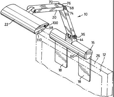
As shown in Figures 1, 3 and 4, the present invention comprises an
illuminating device or picture lamp 10 especially adapted for mounting on a
picture frame 12 which can be of standard construction. This lamp 10 is
constructed for the purpose of lighting a picture or display mounted in the
picture frame 12 which can be hung on a vertical wall 14. It will be
understood
that the picture frame can be hung in the usual manner, for example, by means
of picture wire and hook shaped fasteners or nails mounted on the wall, these
fasteners not being shown in Figure 3. The picture lamp of the invention
comprises several major components including an elongate housing 16 capable
of holding at least one battery therein and preferably two or three batteries,
at
least one support wing 18 rigidly connected to the housing, a support arm 20,
and an electrical light receptacle 22 mounted on an outer end of the support
arm. There is also an electrical circuit indicated generally at 24 in Figure 2
for
operating the one or more light bulbs of the picture lamp by operatively
connecting these bulbs to the battery or batteries installed in the lamp. It
will be
noted that in the preferred illuminating device illustrated in the drawings,
there
are in fact two support wings 18 each having a generally rectangular shape and
each projecting downwardly from a lower section of the housing. The preferred
CA 02331928 2001-01-22
-5-
support wings 18 are substantially planar as shown and they extend
substantially tangentially from the lower section of'the housing as
illustrated in
Figure 3. It will be understood that the position of the wings 18 relative to
the
housing enables these wings to be easily inserted between the surface of the
wall 14 and the back of the picture frame 12 as shown in Figure 3. Thus, these
wings can extend downwardly between the wall and the rear surface of the
picture frame in order to hold the picture lamp 10 on a top portion or top
surface 26 of the picture frame. Thus, because of the positioning of the wing,
the bottom surface of the battery housing can rest on the top of the picture
frame and, in this way, the picture lamp will be supported by the picture
frame.
The preferred wings 18 are made of plastic and are integrally formed on the
housing 16 when the housing is molded. The size of the wings can vary but in a
preferred embodiment they are eight to ten inches in length. The two support
wings are located at opposite end sections of the housing 16. It will be
understood that instead of two wings, there could be a single, large support
wing or there could be more than two wings. The provision of wings at
opposite ends of the housing helps to provide stability for the mounting of
the
picture lamp.
Turning now to the preferred construction of the housing itself, the
illustrated housing is hollow and is capable of holding three batteries 30, 32
and
34 in end-to-end alignment as shown in Figure 5. The size and type of battery
will depend on the size of the lamp and its intended. use. The preferred
batteries
of the illustrated lamp can be AA batteries. The housing 16 has a pivot arm
connection 36 on an upper side thereof and located midway along the length of
the housing. The support arm 20, which is preferably hollow, is pivotably
connected at an inner end thereof to the pivot pin connection 36 which
projects
upwardly from the upper side of the housing. The connection 36 is on either
side of a wire passageway 38 for passage of electrical wiring therethrough.
This
CA 02331928 2001-01-22
-6-
wiring 40 is part of the aforementioned electrical circuit 24. The connection
36
can be an integral lug-type connector that is formed when the housing is
molded and thus it is made from plastic. This connector has a pivot pin hole
42
and a suitable pivot pin 44 made of plastic or metal extends through both
sections of the connector as well as through connecting section 46 integrally
formed on the inner end of the support arm. The connecting section 46 is
formed with a wire slot 48 through which the aforementioned wiring 40 can
extend from the inside of the support arm 20 and into the housing 16.
The interior of the housing 16 can be seen in Figure 5 which shows the
three batteries mounted therein. The elongate housing 16 as shown is
substantially cylindrical both on its exterior and on the interior. However,
inside the housing there can be a number of circumferentially extending ribs
52
which not only support and locate the three batteries but also help strengthen
the housing itself. Also, mounted at opposite ends of the housing are metallic
spring contacts 56 and 58 which are electrically connected to the wiring 40.
In
order to gain access to the battery compartment in the housing, there is a
battery
cover 60 which, as illustrated in Figures 4 and 7 is located on the front side
of
the housing. The battery cover can be secured to the housing in the usual
manner, for example by means of short projecting legs that extend into the
main body of the housing and a spring clip (not shown). As the construction of
battery covers are well known in the art of battery operated appliances, a
detailed description herein is deemed unnecessary. The preferred illustrated
battery cover is curved in the transverse direction of the housing with its
exterior radius of curvature, indicated by R in Figure 7, corresponding
substantially to that of the housing 16.
Turning now to the support arm 20, the preferred illustrated arm has a
first elongate arm section 20A and a second elongate arm section 20B. These
two sections are pivotably connected to each other at a joint 66. Preferably
this
CA 02331928 2001-01-22
-7-
joint is located about midway along the length of the support arm 20. The arm
section 20A can have two, separated pivot pin holding sections 68 and 70. Each
of these sections has a pivot pin hole (not shown) through which can extend a
suitable pivot pin 74 made of metal or a suitably strong plastic. The second
arm
section 20B can have a centrally located pivot pin holding section 76 formed
with a pivot pin hole and a central slot for wiring (not shown). Thus, the
wiring
40 that passes through the arm sections 20A and 20B can pass through the
central slot and thus will be hidden from view. The preferred illustrated arm
sections are hollow, tubular members so that the wiring cannot be seen. As
illustrated, these arm sections have a rectangular transverse cross-section
but it
will be appreciated that the cross-section could also be square and it can be
made round as well, if desired. Instead of using hollow, tubular arm sections,
the arm sections 20a and 20b can each be channel-shaped with an open bottom.
This shape would also tend to hide the wiring 40, particularly if the support
arm
is properly positioned relative to the picture that is being illuminated. In
the
case of a channel-shaped arm section, wire holders can be located inside the
arm section to maintain the wire inside of the arm section (not shown).
The aforementioned light receptacle 22 is pivotably connected to the
second arm section 20B at a joint indicated generally at 80 in Figure 5. This
joint is located about midway along an elongate rear edge portion 82 of the
receptacle. The joint 80 can be constructed in a manner similar to the joint
66
shown in Figure 6. This joint also has a pivot pin 84 which extends through
two, separated pin holding sections 86 and 88 formed on the outer end of the
second arm section 20b. The pin also extends through a pin holder 90 formed
on the rear edge section of the light receptacle.
The preferred illustrated receptacle 22 holds two relatively small light
bulbs 92 and 94 that are mounted in suitable light bulb holders 96 which in
turn
are secured in the receptacle. Also mounted on the receptacle is a standard on-
CA 02331928 2001-01-22
-g-
off switch 98 which is part of the electrical circuit 24. This switch can be
mounted on a sidewall 100 of the receptacle.
The preferred light receptacle has a plastic housing indicated generally
at 102. This housing has an elongate top which is curved in transverse cross-
section as illustrated in Figure 6. Mounted on the inside of this top can be
two
rectangular pieces of reflective film 104. This film, which can be secured in
place by adhesive, forms a reflector which directs the light from each bulb
downwardly towards the picture or display. Preferably the light passes through
a clear, plastic prismatic lens 110 which can be made of tough, durable
acrylic.
The receptacle housing is formed with a bottom wall 112 with an upwardly
extending flange 114 which supports a rear edge section of the lens 110. The
bottom wall 112 extends the entire length of the receptacle and is connected
at
each end to the sidewalls 100. Thus, both the bulbs and the wiring in the
receptacle are completely enclosed by the receptacle. Preferably the bulbs are
high efficiency bulbs in order to reduce the amount of electrical power drawn
from the batteries.
It will be appreciated that various modifications and changes can be
made to the described illumination device without departing from the spirit
and
scope of this invention. Accordingly, all such modifications and changes as
fall
within the scope of the accompanying claims are intended to be part of this
invention.