Note: Descriptions are shown in the official language in which they were submitted.
CA 02331938 2001-O1-22
COLLAPSIBLE BAG HOLDER
Field of Invention
This invention relates to containers. In particular, this invention relates to
a collapsible
bag holder for supporting a bag, for example for use as a trash container.
Background of the Invention
Organization is important to the efficient use of a workspace in the home,
such as a
workshop or kitchen, laundry room, garage and the like, and commercial,
industrial or
institutional workspace such as hospitals, manufacturing facilities etc.
Particularly in a small
workspace, such as a garage or basement workshop, it is advantageous to
maintain as much
free space as possible for working with tools and materials. One of the ways
to maintain an
organized workshop environment is through the efficient disposal and storage
of trash and
refuse.
Because trash bags are not self supporting, trash and refuse is typically
discarded in a
rigid-walled refuse container such as a trash can, which provides a supporting
structure for
the temporary storage of trash and refuse. Often the trash can is lined with a
bag, to facilitate
transfer of trash to a disposal location for garbage pickup. Typically the lip
about the bag
opening is folded over the rim of the container to hold the bag open for easy
use. But since
the bag is rarely the same shape as the container, and thus is unlikely to
line the interior wall
of the container closely, as the bag is filled it tends to be pulled into the
container by the
weight of the trash and drawn off of the rim of the container, which makes it
awkward to
continue filling the bag.
If the refuse container is not lined with a bag, the trash must be transferred
from the
trash can to a bag for disposal, so the container must be invertible. This
renders it impractical
to mount the container, which can thus occupy considerable floor space. In a
small workspace
this can be inconvenient and an inefficient use of space.
Another disadvantage of using a rigid-walled refuse container, particularly in
a small
workspace, is that the container occupies the same volume of space whether the
container is
full, partially filled or completely empty. The container can thus
unnecessarily occupy a
relatively large portion of the workspace even when it is empty or only
partially filled.
-1-
CA 02331938 2001-O1-22
Still a further disadvantage to using a rigid-walled trash container is that a
separate
component such as a lid is required to close the container when not in use.
This is particularly
disadvantageous in the case of decomposable trash such as food and other
organic matter,
which is often encountered in a workspace such as a kitchen. The need for a
separate lid in
these situations is inconvenient and renders the container more expensive to
manufacture.
Summar~of the Invention
The present invention overcomes these disadvantages by providing a collapsible
bag
holder for supporting a free-hanging bag. The bag holder according to the
invention is
mounted in any convenient location, to support the bag with the bag opening
retained in a
open condition for disposal of trash, and can be collapsed to support the bag
with the bag
opening retained in a closed, substantially sealed condition in which the
space occupied by
the trash bag is only as large as the volume of trash contained within the
bag.
The invention accomplishes this by providing a frame comprising a stationary
rear
frame member, a movable front frame member movable between open and closed
positions,
and opposed folding side frame members which can be collapsed to move the
front frame
member to the closed position and extended to move the front frame member to
the open
position.
The frame may be mounted to the supporting structure by any suitable means. In
a
preferred embodiment the collapsible bag holder is mounted to a bracket
affixed to the
supporting structure, which provides clips that detachably lock under the
front frame member
to releasably retain the frame in a collapsed position. In a further
embodiment the frame may
be composed of a magnetic material such as steel, and a magnet retains the
frame in the
closed position.
In the preferred embodiment the rear frame member comprises a flange which
underlies the front frame member when the frame is in the closed position, and
a resilient
strip extending along the flange which compressibly engages against the bag
wall when the
frame is in the closed position, substantially sealing the bag.
The holder of the invention preferably includes retaining strips for retaining
the bag
wall on the frame, each comprising a resilient channel which compressibly
engages the bag
wall against the respective front and rear frame members.
-2-
CA 02331938 2001-O1-22
The present invention thus provides a collapsible holder for mounting to a
supporting
structure, for supporting a flexible bag having a flexible bag wall and a top
opening, the
holder comprising a frame comprising: a stationary rear frame member, a
movable front
frame member, movable between an open position spaced from the rear frame
member to
retain the top opening in an open condition, and a closed position
substantially abutting the
rear frame member to retain the top opening in a closed condition, and opposed
folding side
frame members, each side frame member having an intermediate hinge and
hingedly affixed
to ends of the front and rear frame members, wherein when the holder is
mounted to a
supporting structure and the top opening of a bag is affixed to the frame, the
side frame
members can be collapsed to move the front frame member to the closed position
and can be
extended to move the front frame member to the open position.
The present invention further provides, in combination, a flexible bag having
a
flexible bag wall and a top opening, and a collapsible holder for mounting to
a supporting
structure, the holder comprising a frame comprising: a stationary rear frame
member, a
movable front frame member, movable between an open position spaced from the
rear frame
member to retain the top opening in an open condition, and a closed position
substantially
abutting the rear frame member to retain the top opening in a closed
condition, and opposed
folding side frame members, each side frame member having an intermediate
hinge and
hingedly affixed to ends of the front and rear frame members, wherein when the
holder is
mounted to a supporting structure and the top opening of a bag is affixed to
the frame, the
side frame members can be collapsed to move the front frame member to the
closed position
and can be extended to move the front frame member to the open position.
In further aspects of the invention, the frame is mounted to a bracket affixed
to the
supporting structure, the bracket providing clips which detachably lock under
the front frame
member to releasably retain the frame in a collapsed position; the frame is
composed of
metal; one of the front frame member or the rear frame member comprises a
flange which
underlies the other of the front frame member or the rear frame member when
the frame is in
the closed position; the flange is provided along the rear fr~~rne member and
the flange or a
bottom portion of the front frame member, or both, is provided with a
resilient strip which
compressibly engages against the bag wall when the frame is in the closed
position; the
intermediate hinges are disposed generally centrally along the side frame
members; the holder
further comprises retaining strips for retaining the bag wall on the frame,
which may extend
-3-
CA 02331938 2001-O1-22
along top edges of the front and rear frame members and may comprise resilient
channels
which compressibly engage the bag wall against the frame members; and/or the
frame is
removably mounted to a bracket by opposed slots in the bracket spaced from the
supporting
structure and adapted to receive the rear frame member.
Brief Description of the Drawings
In drawings which illustrate by way of example only a preferred embodiment of
the
invention,
Figure 1 is a perspective view showing the invention supporting a bag in the
open
condition,
Figure 2 is a perspective view showing the frame of Figure 1 in a partially
closed
condition,
Figure 3 is a perspective view showing the frame of Figure 1 in a fully closed
condition,
Figure 4 is an enlarged perspective view of the closing mechanism in Figure 2,
Figure S is a top plan view showing the frame of Figure 1 in the open
position, and
Figure 6 is a perspective view of a further embodiment of the invention
supporting a
bag in the open condition.
Detailed Description of the Invention
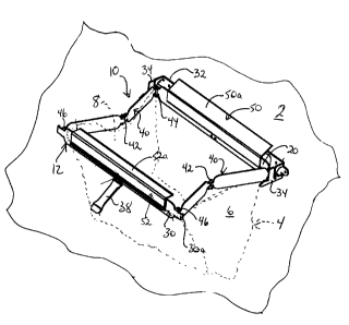
Figure 1 illustrates a preferred embodiment of the collapsible holder 10 of
the
invention, mounted to a supporting structure 2, such as a wall, table top,
pegboard etc., and
supporting a trash bag 4 (shown in phantom lines) having a flexible bag wall 6
and a top
opening 8. The holder 10 comprises a frame 12 comprising a stationary rear
frame member
20, a movable front frame member 30 and opposed folding side frame members 40.
In the
preferred embodiment the frame 12 is composed of steel, however the frame 20
may be
composed of any other suitably rigid material including other metals such as
aluminum,
plastic, wood, or any combination thereof.
The frame 12 may be provided with any suitable mounting means for mounting the
holder 10 to a supporting structure 2. In the embodiment shown mounting means
comprises a
-4-
CA 02331938 2001-O1-22
bracket 32 from which projects generally forwardly clips 34 which removably
receive the rear
frame member 20, as described below. This provides the advantage that the
frame 12 is
readily removable for cleaning or relocation; however the frame 12 may be
mounted in any
other suitable fashion.
Each side frame member 40 has an intermediate hinge 42 which allows the side
frame
members 40 to fold at an intermediate point, preferably generally centrally.
The side frame
members 40 are also hingedly affixed to the ends of the rear and front frame
members 20, 30
at hinges 44, 46, respectively. This allows the side frame members 40 to
collapse, preferably
inwardly to conserve space, so that the front frame member 30 is movable
between an open
position spaced from the rear frame member 20 to retain the top opening in an
open
condition, as shown in Figure 1, and a closed position substantially abutting
the rear frame
member 20, as shown in Figure 3, to retain the top opening 8 of the bag 4 in a
closed
condition. The side frame members 40 are preferably restricted from extending
to 180
degrees, to ensure that they collapse inwardly merely by movement of the front
frame
member 30. The front frame member 30 may optionally be provided with a handle
38 to
facilitate opening and closing the holder 10.
According to the preferred embodiment the clips 34, best seen in Figure 4,
each
project generally forwardly from an end of the mounting bracket 32 and provide
a slot 34a
into which a portion 20a of the rear member 20 is slidably disposed, to mount
the frame 12 to
the bracket 32. In the preferred embodiment the clips 34 further provide a
ledge 34b having a
top edge with a depression 34c in which a portion 30a of the front frame
member 30 rests
when the frame 12 is in the closed condition, as shown in Figure 3, to thus
retain the frame 12
in the closed condition under the weight of the bag 4 and its contents.
In a further embodiment one of the front frame member 30 or the rear frame
member
20 may be provided with a magnet 22 affixed by epoxy or any other suitable
means. In this
embodiment the frame 12 preferably is composed of or comprises a magnetic
material, so that
when the holder 10 is moved to the closed position shown in Figure 3, magnetic
attraction
between the magnet 22 and the rear or front frame member 20 or 30 retains the
frame 12 in
the closed position. If the frame 12 is not composed of a magnetic metal, a
separate piece of
magnetic material can be affixed to the frame 12 opposite the magnet to allow
the frame 12 to
-5-
CA 02331938 2001-O1-22
be magnetically retained in the closed position. Other means may be used to
retain the holder
in the closed position.
The invention also provides means for sealing the bag 4 when the holder 10 is
in the
closed position. In the embodiment of Figure 6, the bottom edge of the rear
frame member 20
comprises a flange 24, which is preferably formed integrally with the rear
frame member 20
and underlies the front frame member 30 when the frame 12 is in the closed
position. Thus, in
the closed condition the bag wall 6 passes between the lower edge of the front
frame member
30 and the upper surface of the flange 24.
In the preferred embodiment the flange 24 is provided with a resilient strip
26, for
example a compressive urethane foam strip such as is used as weather
stripping, extending
along the flange 24, preferably along substantially its entire length. The
strip 26 compressibly
engages against the bag wall 6 when the frame 12 is in the closed position to
substantially
seal the bag 4 and thus retain unpleasant odors within the bag 4. This can be
advantageous in
the case of decomposable refuse, such as organic matter, or chemical refuse
such as rags or
paper litter used for cleaning oil-based solvents or the like. It will be
appreciated that the
resilient strip 26 could instead be disposed along a bottom portion of the
front frame member
30, or resilient strips 26 could be disposed along both the flange 24 and the
front frame
member 30 to seal the bag 4 in a similar fashion. It is also possible to
position the flange 24
so that there is a tight fit between the flange 24 and the bottom edge of the
front frame
member 30, or to provide a bead or recess which the bottom edge of the front
frame member
30 abuts in the closed position, but these rigid sealing structures are not
preferred because
repeated closing and opening of the holder 10 could tear the bag wall 6.
The flange 24 may alternatively be provided along the lower edge of the front
frame
member 30, to underlie the rear frame member 20 when the frame 12 is in the
closed position,
although this is not preferred as it may require that the frame 12 be spaced
too far from the
supporting structure 2 in order to accommodate the flange 24 as the frame 12
is collapsed to
the closed position.
The invention may include means for securing the bag 4 to the holder 10. In
the
preferred embodiment retaining strips 50, 52 are provided for retaining the
bag 4 on the frame
12. Preferably the retaining strips 50, 52, comprising resilient channels,
extend along the top
-6-
CA 02331938 2001-O1-22
edges of the rear and front frame members 20, 30, respectively, to
compressibly engage the
bag wall 6 against the frame members 20, 30. The rear retaining strip 50 may
optionally have
a backstop flap SOa covering any space between the rear frame member 20 and
the supporting
structure 2, as shown in Figure 1, and the front retaining strip 52 may
optionally have a cover
flap 52a covering the space between the front frame member 30 and the rear
frame member
20 when the frame 12 is closed, as shown in Figure 3.
In use, the holder 10 is mounted to a supporting structure 2 by fastening
mounting
bracket 32 to any convenient support structure 2 such as a wall, worktable
etc., as by screws
or any other suitable fastener, and engaging the extension portions 20a of the
rear frame
member 20 into the slots 34a. With the frame 12 in the open position shown in
Figure 1, the
bag 4 is affixed to the frame 12 by inserting the bag 4 through the frame 12,
folding the bag
wall 6 about the top opening 8 over the rear and front frame members 20, 30,
and slip-fitting
the retaining strips 50, 52 over the top edges of the rear and front frame
members 20, 30,
respectively, to secure the bag 4 thereto with the bag wall 6 largely
suspended beneath the
holder 10, as shown in phantom lines in Figures 1 and 6.
Once the bag 4 has been installed to the frame 12, the side frame members 40
can be
collapsed by manually pushing the front frame member 30 toward the rear frame
member 20,
to move the front frame member 30 to the closed position, as shown in Figures
2 and 3. In the
fully closed position of the embodiment of Figure 1, the bottom edges of the
extension
portions 30a of front frame member 30 rest in the depressions 34c in the upper
edges of clips
34. In the embodiment of Figure 6 the magnet 22 magnetically attaches to the
front frame
member 30 to retain the holder 10 in the closed position, and the resilient
strip 26 compresses
the bag wall 6 against the bottom edge of the front frame member 30 to
substantially seal the
bag 4.
To open the holder 10 for depositing trash into the bag 4, the front frame
member 30
is manually drawn away from the rear frame member 20, using sufficient force
to overcome
the engaging force of ledges 34b in the embodiment of Figure 1 (or the
magnetic attraction in
the embodiment of Figure 6), and the side frame members 40 are thus extended
as the front
frame member 30 moves to the open position shown in Figure 1. Opening the
frame 12 in this
fashion tensions and thus straightens the bag wall 6, fully exposing the top
opening 8 of the
bag 4 for use.
CA 02331938 2001-O1-22
A preferred embodiment of the invention having been thus described by way of
example only, it will be apparent to those skilled in the art that certain
modifications and
adaptations may be made without departing from the scope of the invention, as
set out in the
appended claims. The invention has been described in the context of its use as
a trash or
refuse container in a workspace, however it will be appreciated that the bag
holder of the
invention can be used in other environments and for other purposes without
departing from
the scope of the invention.
_g_