Note: Descriptions are shown in the official language in which they were submitted.
CA 02331947 2000-11-14
WO 99160370 PCT/IL99/00250
METHOD AND APPARATUS FOR GENEItATIN(~ CE>NTROLLED TORQUES ON
OBJECTS PARTICULARLY OBJECTS INSIDE A LIVING I30DY
FIELD AND BACKGROUND OF THE INVENTION
'fhe present invention relates to a method and apparatus for generating
controlled torques on objects.
1'he invention is particularly useful for generating controlled torques in
order to steer objects
through a living body for purposes of performing minimally-invasive diagnostic
or interventional
procedures, and the invention is therefore described below 'with respect to
such an application.
BACKGIZOE.JND
Minimal ly-invasive diagnostic or interventional procedures require three
classes of devices -
viewing devices to provide feed-back to the operator (since direct viewing as
in open surgery is not
available), operational devices (,i.e. tools to perform the task}, and
controller devices which
manipulate or navigate the operational devices. Most commonly, viewing devices
are based on
optical instrumentation with optic fibers or imaging modalitifa Iike X-ray,
ultrasound, computerized
tomography (CT) or magnetic resonance imaging (MRl). The operational devices
vary with the
procedure - endoscopes and catheters for diagnostic and interventional
procedures; and miniature
specialized tools for laparoscopic and other minimally-invasive interventions.
The control of the
devices is most commonly achieved by mechanical mechani:>ms. Examples include:
1 ) endoscopes,
which are inserted into a lumen (e.g. the gastro-intestinal tract, the
bronchial tree}, are navigated by
viewing through the endoscopes. and have mechanical control of the lip
direction; 2) catheters
which arc inserted through blood vessels, either veins or arteries, to perform
diagnostic procedures
(e.g. coronarycatheterization) orinterventions (e.g. angioph~sty of stenosed
bloodvessels orcardiac
valves), and are navigated by mechanical manoeuvres (e.g, combinations of
pushing, pulling and
twisting of the external portion of the catheter) together with real-time
viewing of the blood vessels
and the catheters using X-ray imaging; and 3) various rigid devices for
cellular aspiration. tissue
biopsy, or other diagnostic and interventional procedures, which are inserted
with real-time guiding
(e.g. by ultrasound) or by stereotaxis guidance.
Computer-assisted stereotaxis is a valuable technique for perfonming
diagnostic and
inierventional procedures, most typically with the brain. During traditional
stereotaxis. the patient
wears a special halo-like headframe, and CT or MIZI scans are performed to
create a
three-dimensional computer image that provides the exaca location of the
target (e.g. tumor) in
CA 02331947 2000-11-14
WO 99/60370 PCT/iL99/00250
relation to the headframe. When this technique is used for biiopsy or
minimally-invasive surgery of
the brain, it guides the surgeon in determining where to make a small hole in
the skull to reach the
target. Newer technology is the frameless technique, using a navigational wand
without the
headframe (e.g. Nitin Patel and David Sandeman, "A Simple Trajectory Guidance
Device that
Assists Freehand and Interactive Image Guided Biopsy of Small Deep
Intracranial Targets", Comp
Aid Surg 2:186-192, 1997).
Many of the advantages of MRI that make it a powerful clinical imaging tool
are also
valuable during interventional procedures. The lack of ionizing radiation, and
the oblique and
multiplanar imaging capabilities, are particularly useful dut~ing invasive
procedures. 'fhe absence
of beam-hardening artifacts from bone allows complex approaches to anatomic
regions that may be
difficult or impossible with other imaging techniques such as conventianal CT.
Perhaps the greatest
advantage of MRI is the superior soft-tissue contrast resolution, which allows
early and sensitive
detection of tissue changes during interventional procedures. Many experts now
consider MRI to
be one of the most powerful imaging techniques to guide inte:rventional
interstitial procedures, and
in some cases even endovascular or endoluminal procedures (Yoshimi Anzai, Rex
Hamilton,
Shantanu Sinha, Antonio DeSalIes, Keith Black, Robert Lufkin, "Interventional
MRI for Head and
Neck Cancer and Other Applications", Advances in Oncology, May 1995, Vol 11
No. 2).
Virtually all current guiding and manipulation methods are based on various
mechanical or
electro-mechanical modules. For example, steerable catheters use tension wires
to bend the tip of
the catheter to the desired direction, and typically enable bending in one
plane; endoscopes have
mechanical control of the tip direction in two orthogonal planes, using two
knobs on their control
unit; rigid devices are oriented externally before they are inserted into the
body to reach the defined
target_ The major drawback of these mechanisms is their relative complexity
and high cost, which
typically result with devices for multiple use.
A somewhat different approach to navigation and manipulation is based on
magnetic
stereotaxis. Current stereotactic procedures with rigid devices, although less
invasive than open
surgery, may still damage various structures along the path ~of insertion. The
magnetic stereotaxis
instrumentation (Stereotaxis Inc., St. Luis, MO) is less de:;tructive.
According to this technique
surgeons insert a magnetic pellet the size of a rice grain into a small hole
drilled into the skull of a
patient, and the patient's head is then placed in a housing which contains six
superconducting
magnets. Using previously recorded MRI or CT images or n~ai-time X-ray imaging
as a guide, the
surgeon directs the pellet through the brain by adjusting the forces ofthe
various magnets. The pellet
could tow a catheter, electrode or other device to the target. T-Iowever,
magnetic stereotaxis cannot
CA 02331947 2000-11-14
WO 99!60370 PCT/IL99/00250
be used with real-time MRI because of the Mltl scanner's strong magnetic
#ield, which precludes
Lhe use of magnetic objects inside the body during MRI scanning.
From the presented background on current methodologies, one can define the
ideal system
for minimal invasive procedures: It should provide real-time, 3-dirriensional,
non-ionizing imaging
(like MRI or ultrasound) as feed-back to the user for optimal insertion and
intervention; and it
should implement flexible, miniaturized devices which can be manoeuvred
through an optimal path
to minimize damage to healthy tissues and sensitive organs.
OBJECTS AND BRIEF SUMMARY OF THE INVENTItJN
One object of the present invention is to provide a method and apparatus for
generating
controlled torques to be applied to objects, which method amd apparatus are
particularly useful for
maneuvering miniaturized devices through an optimal path in a living body to
minimize damage to
healthy tissues and sensitive organs.
Another object of the present invention is io provide; a method and apparatus
to control and
manipulate a device inside a living body through the generation of magnetic
dipoles in the device
which interact with an external magnetic field, like the magnetic field of an
MRI system, and thus
generate torque or torques for controlling and manipulating; the device.
DESCRIPTION OF PREFERRED LMBODIMEN'fS
According to one aspect of the present invention, there is provided a method
of generating
a controlled torque of a desired direction and magnitude in an object within a
living body,
comprising: producing an external magnetic field of knov~rn magnitude and
direction within the
body; applying to the object a coil assembly including at le~~st three coils
whose axes are of known
orientation with respect to each other and have components in the three
orthogonal planes; and
controlling the electrical current through the coils to cause the coil
assembly to generate a resultant
magnetic dipole interacting with the external magnetic fi<;ld to produce a
torque of the desired
direction and magnitude.
According to further features in the preferred embodiment described below, the
coils have
axes oriented orthogonally with respect to each other; and the external
magnetic field is a steady,
homogenous magnetic field, particularly the main magnetic; field of an MRI
(Magnetic Resonance
lrraaging) system.
CA 02331947 2000-11-14
WO 99/60370 PCT/IL99/00250
MR1 is rapidly becoming the preferred methodology for minimal invasive
diagnostic and
interventional procedures because of its non-invasiveness, high resolution,
high contrast between
different soft tissues. and absence of shadowing by bones. Recent
technological improvements in
MRI systems provide rapid scanning sequences, which enable real-time imaging
during the
procedure, and an open architecture which enables access. to the patient. The
present invention
makes use of~a basic, universal component of the MRI system - the steady,
homogenous magnetic
field B0, typically generated by a superconducting electromagnetic coil; but
the invention may also
be applied with other sources of external or internal magnetic folds.
Any magnetic field exerts torque on magmetic dipoles, like the one generated
by an electrical
current in a closed-loop wire or a coil (Blot-Savart and Ampere Laws). The
torque on the coil
depends on the relative direction of the dipole with respect to the direction
of the magnetic field.
With at least three coils, for example three orthogonal coils, a magnetic
dipole with any spatial
direction can be generated: each coil generates a dipole, which can be
represented by a vector, and
the combined three coils generate a dipole which is the vectorial surn of the
three dipoles.
One oan generate such a dipole with any magnitude and direction by controlling
the electrical
currents through each of the three individual coils, which determine the
magnitude of the dipole in
each coil. If the orientation of the three coils in the magnei:ic field is
known, a specific magnetic
dipole (i.e. with specific magnitude and direction) can b~e generated. This
controllable dipole
interacts with the external magnetic field to generate a controllable torque,
namely a torque with a
specific magnitude and direction.
The generated torque can be used to bend the tip of a catheter or endoscope
and thus to
enable the operator to advance the device in the required direction.
Furthermore, the torque can be
used to operate various devices to perform different activities inside the
body, similar to mechanical
devices used during Iaparoscopic procedures. For example, a pliers-like
clamping mechanism can
be used to hold or release objects inside the body; a miniatur<s cutting
device can be used to perform
remote surgery; and a miniature stapler-like device can be used to suture
structures.
'rhe present invention has significant advantages over existing methodologies.
Compared
with mechanical devices for navigation and operation of various diagnostic and
interventional
devices, electromagnetic devices constructed in accordance with the present
invention for the same
tasks wilt be smaller, Cheaper, and will enable more precise; control of the
position, direction and
operation of the device.
CA 02331947 2000-11-14
WO 991b0370 PCT/IL99/Ot)250
BRIEF DESCRIPTION OF TIDE DRAWINGS
The invention is herein described. by way of example only. with reference to
the accompanying
drawings. wherein:
Fig. I is a block diagram illustrating one form of apparatus; constructed in
accordance with the
present invention for use in an MItI system for steering an intra-body
operational device in
order to perform a diagnostic or interventional procedurf:;
Fig. 1 a more particularly illustrates one form of torque-generating module in
the apparatus of
Fig. I ;
Figs. 2a and 2b schematically illustrate the use of a joy stick for
controlling the- position and
direction of an intra-body device, such as the tip pf a catheaer, endoscope,
or optical fiber;
Figs. 3a and 3b schematically illustrate the use of a joy stick with a slide
for controlling the
operation of an intra-body miniature cool, such as a clamping, cutting, or
stapling device;
Fig. 4 is a diagram more particularly illustrating the operation of the
location and direction module
{LDM) in the apparatus of Fig. 1;
Fig. 5 is a diagram which explains our way to generate a rr~agnetic dipole in
the torque generating
module in order to rotate or bend the intra-body device or part of it to a new
direction-.
Figs. 6a and 6b diagrammatically illustrate, in a simplified t:wo-dimensional
display, the manner of
creating a specific magnetic dipole by summing the dipoles generated by three
orthogonal coils; and
Fig. 7 illustrates the functioning of the invention in steering a device
during MRI imaging.
DETAILED DESCRIPTION OF THE PREFEKRED EM130D1MENT
The following description relates to a preferred embodiment of the invention,
namely to a system
for generating controllable torques in a device under MRI imaging. Fox the
sake of simplicity, the
preferred embodiment is presented with reference to the us;e of an MRI
system's magnet field, but
the invention may be implemented with other sources o~f external or internal
magnetic fields.
CA 02331947 2000-11-14
WO 99/60370 PCT/IL99/00250
Potential clinical applications of the described core technology are
described. In the following,
vectors are underlined, to distinguish them from scalars.
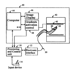
The apparatus illustrated in Fig. 1 includes a processing and control unit 10,
a torque-
generating module (TGM) 20, which is incorporated in an intro-body device 30,
and an electronic
interface unit 12. The intro-body device 30 is manipulated through the
interaction between the
homogenous, main magnetic field (BO) of the MRI system 40, which is generated
by the MRI
magnet 42, and the magnetic dipoles generated by the micro-coils 22, 24, 26 in
the torque-generating
module 20.
The coils 22, 24, 26, as more particularly illustrated in Fig. 1 a, have axes
of known
orientation with respect to each other, which axes have components in the
three orthogonal planes.
Preferably, their axes are oriented orthogonally with respect to each ocher as
shown in Fig. la. As
will be described more particularly below, the electrical currents through
coils 22, 24, 26 may be
controlled by the processing and control unit IO to cause the coils assembly
20 to generate a
resultant magnetic dipole interacting with the homogenous magnetic field
produced by the MRI
magnet 42 to produce a torque of the desired direction and nnagnitude, which
is applied to the intra-
body device 30, to steer it or to otherwise activate it.
The processing and control unit I 0 interacts with the MIDI computer 44 and
with the gradient
activation control unit 48 which provide the processing and control unit with
information on the
MRI system electro-magnetic gradient fields (B I ), generate.d by the set
of~three orthogonal gradient
coils 43, and the timing sequence of the activation of the theae coils during
M1ZI scanning. The MRI
system provides the operator with a real-time image of the operation f eld
through either the
standard MKI display or a specialized monitor 46. An optional location and
direction module
(LDM) SO may be incorporated into the intro-body device 30 to provide its
location and direction
or orientation.
In Fig. 1, the MIDI system 40 provides the operator with a real-time display
46 of the body.
The MRI computer 44 provides the processing and control unit 10 with the
spatial distribution of
the gradient magnetic fields as a function of time, to enable real-time
localization of the device. The
computer 44 also provides the processing and control unit 1 (? with the event
schedule of the MR.I
system to prevent image artifacts due to the activation of tl'ae torque-
generating module (TGM) 20
6
CA 02331947 2000-11-14
WO 99160370 PCT/IL99100250
when the MItI gradient fields are activated for imaging. The MRI computer 44
can be programmed
to perform real-time imaging of the region around the current location of the
intra-body device 30
to enable fast update of the image as the device is advanced or is manipulated
by the operator.
Typically, the operator manipulates the device 30 by controlling a torque on
specific parts
of~the device, which are termed the manipulated parts. For example, Figs. 2a
and 2b illustrate how
the intra-body device 3U, such as a catheter, endoscope, or optical #iber, can
be directed through a
passageway 32, such as blood vessel bifurcations, the bronchial tree, or the
gastrointestinal tract,
by bending its leading tip to the required direction by manipulating a
joystick 16 of an input device
14 to the processing and control unit 10.
Figs. 3a and 3b illustrate how a miniature clamp 1:30 can be opened or closed
by exerting
torques on its jaws by manipulating a slide 1 18 on the input device 114,
which input device also
includes a joystick 116 to steer the miniature clamp 130 to the proper
location.
1'he location and direction of the intra-body device 30 (or 130) and its
manipulatable parts
are either measured from the MRI images, or are determinf:d by an optional
location and direction
module (LDM) 50 (Fig. 1). The capability of location tracking by the MRI is
available with any
commercial system, provided that the intra-body device is made of material
having high contrast
with biological tissues (e.g. Smits HFM and Bakker CJG, , "Susceptibility-
Bases Catheter
Visualization'', in "Interventional Magnetic Resonance Imaging", edited by
Debatin JF and Adams
G, Springer, 1998) or has a small receiving coil which is sensitive to near-
neighbourhood emitted
radio-frequency signal during the MR imaging process (Dumoulin CL, Darro RD,
Souza SP,
"Magnetic Resonance Tracking", in "Interventional MR"', edited by Jolesz FA
and Young IY,
Mosby, 1998).
Fig. 4 illustrates an approach to sense the location of the device using a
dedicated module,
namely, the location and direction module (LDM) 50, which comprises of a set
of three sensing
coils. The three sensing coils may be the same three coils 22, 24, 26 of the
torque-generating module
(TGM} 20, or another set of coils optimized for their use in the LDM.
The MRI alternating gradient magnetic fields (B 1 ) induce electromotive
forces (E) in the
sensing coils, and the magnitudes of the induced electromotive forces are
related to the magnetic
7
CA 02331947 2000-11-14
WO 99/6037~ PCT/IL99l00250
flux D through the coil, as given by Faraday Law:
( 1 ) E = -dt~/dt
where the magnetic flux O is determined by the total magnetic field (B = BO+B
1 ), the coils effective
area (which in a case of~coil with multiple loops equals the: sum of the area
of all the loops in the
coii), and the direction ofthe magnetic field with respect toothe spatial
orientation of the coil, which
is defined by the direction of a unit vector n vertical to the coil surface:
(2) O=BwA
where the dot denotes a vectorial dot product and A is the roil area.
I~ig. 4 shows how the magnitudes of~ the induced electromotive forces and the
known
magnetic field 13 at each point in the operating field (as supplied by the MRI
system's computer)
enable the calculation of the body location and direction by I~quations 3 and
4, set forth below. This
simplified 2-dimensional presentation of Pig. 4 includes only two measured
values E I and E2, while
the full realization of the system requires three values EI., E2, E3 and the
corresponding three-
dimensional equations. Thus for two dimensions the direction and location will
be determined by:
(3 ) 0 = arctan( E.,/E ~ )
(4) (dB/dt)~ = E~' _i. E
where 8 is the direction of the tip of the intra-body device. 30 with respect
to the magnetic field
direction, arid E~ and EZ are the induced electromotive forces in the two
orthogonal coils, and B is
the magnitude of the magnetic field vector B. The electromotive forces are
measured by electrical
circuitry in the electronic interface unit 12, and the measured values are
supplied to the processing
and control unit 10, which calculates the direction 6 and the time-derivative
of the magnetic field
magnitude B. Since the homogenous field BO does not change with time, the
electromotive forces
are determined by the variable magnetic field B1 of the .gradient coils, and
equation 4 can be
rewritten as:
(5) (dBl/dt)~ = E~2 + E~''
8
CA 02331947 2000-11-14
WO 99160370 PCT1IL99/00250
The main advantage of the disclosed methodology - it enables sensing of the
device location
and direction without the need for MRl imaging, so servo control of the
required manipulation of
the device is feasible. Real-time control of the device may be of particular
interest with some of the
clinical applications as presented below.
The processing and control unit 10 receives the time-variable magnitude of the
magnetic
gradient tields B 1 from the MRI system 40 during the activation of the
gradient coils. The
instantaneous location of the sensing coils is determined b_y the processing
and control unit 10 by
comparing the calculated value dB 1 /dt to the supplied values of the held B
1, and fording the spatial
location at which the calculated value of~dBl/dt is cdual to the generated
one.
Knowing the location and direction of the infra-body device and the
manipulated parks, the
MRI display 46 presents this information in addition to the MR image. For
example, during
navigation of a catheter or endoscope, the MR image can be displayed in the
device's coordinate
system, as if the operator is looking forward ti-om the device, witha
synthetic representation of the
tip direction. Alternatively, the image and the intra-body device can be
displayed by using standard
MRI views and sections. Using real-time LDM sensing enables real-time display
of the device
location and direction to the operator. However, other tracking methodologies
can be used instead
of the LDM module.
Based on the composite MRI display of the irnage:d body and the infra-body
device, the
operator manipulates the device using a standard input device 14. As described
above. the direction
of a catheter tip can be controlled by using a joystick 1 G (I~ ig. 2a). The
operator identifies the
required direction to move the catheter by interpretation oil the MR image and
simply moves the
joystick 16 towards the required new direction (Fig. 2b). pigs 3a and 3b, also
described above,
illustrate another example involving the operation of a clarnp 130, where the
operator can use the
joystick 1 I G of input device I 14 to control the direction of the clamp 130
and a slide 1 I $ to control
opening and closing of tlae clamp.
The commands from the input device are fed into thn processing and control
unit 10, which
calculates the required rotation of the manipulated part in the device (e.g.
the tip of a catheter or
optical f ber) as determined by the input command and the current direction of
this part in reference
to the device (e.g. the current direction of the tip). Knowing the direction
ofthc main magnetic field
9
CA 02331947 2000-11-14
_ WO 99/60370 PCT/IL99/00250
BO ofthe MRI system, the processing and control unit calculates the direction
ofthe magnetic dipole
which is required to produce the torque of the required mal;nitude and
direction to manipulate the
part, for example to rotate the tip of a catheter to the new direction. The
magnetic field generates
a torque which rotates the magnetic dipole until it reaches an equilibrium
state where the direction
of the dipole aligns with the direction of the magnetic field.
More specifically, once the direction ofthe device in the MRI coordinate
system is known,
a plane containing the device line of direction and the magnetic field B0 line
of direction is
determined. Referring now to Fig. 5, which presents this plane, the angle
between the magnetic field
direction and the current direction of the device 30 is denoted ~. For the
sake of simplicity in the
presentation, the desired direction of'the device, as determined by the input
from the input device
14, is presented in the same plane (i.e. this is a simplified 2~-dimensional
case) and forms an angle
8 with the current direction of the device. In order to bend th.e tip of the
device to the new direction
defined by the angle 8, a dipole is generated in a direction A; , with respect
to the current direction
of the device, where the angle (x given by:
(6) ar~_8
If the angle a is maintained throughout the steering maneuver, the magnetic
dipole ~.t
interacts with the magnetic field BO to generate a torque whinh bends the
device until it aligns with
the desired direction. at that time the dipole aligns with the direction of
the magnetic field BO and
the resultant torque diminishes to zero. Other implementations can be used,
like using a variable
dipole direction which maximizes the generated torque to induce faster bending
or rotation of the
tip. If a real-time feedback is available by using the LL>M S0, then optimal
control of the
manipulation can be achieved by using servo control of the dipole generation
(e.g. by I'ID
controller).
Referring now to Fig. 6a, the magnetic dipole in the torque-generating module
(TGM) 20
is generated in the required direction by controlling electrical currents in
the three micro-coils 22,
24, 26 of the 1'GM. The pref erred embodiment is with three orthogonal coils,
however other
configurations with orie, two, or more than three coils can be used for
specific applications.
CA 02331947 2000-11-14
WO 99/60370 PCT/IL99/00250
The net dipole in the TGM is calculated by vcctorial sum of the Lhree
individual magnetic
dipoles which are generated by the three coils 22, 24, 2G:
u-~~ +~~+~3
The high intensity homogenous magnetic field BO of the MR1 system interacts
with the
magnetic dipole and generates a torque on the activated pare of the device,
e.g. the tip of the
catheter, endoscope, or optical f ber:
(8) ~ _ ~.t O Bo
where 'C is the generated torque, ~ is the magnetic dipole, C~ is the
vectorial cross product and Bo
is the vectorial representation of the magnetic field BO of the MRI system.
The manipulated part bends or rotates into the required direction and thus
enables the
operator to conduct the required task, for example to navigate the device
Through an optimal path
to minimize damage to tissue or into a bifurcation in blood vessel or another
lumen. In most MRI
syster~-~s tile steady, homogenous ant-directional magn~fic f~~ld I3~ liiTii S
the pOSSiule directiv~IS cf
the generated torque to off axial directions. For example, for MRl system wish
magnetic field in the
Z-direction (the body axial direction), a device positioned in the two
transverse directions can be
bent in one plane and rotated around its axial direction, while a device
positioned in the Z-direction
can be bent in any direction but cannot be rotated. Although this may impose
some limitations on
the operation of the device, correct planning of the procedure, for example
choosing the insertion
point of the device, can overcome this limitation. Furthertruore, any
direction can be achieved by
combining two manipulations in the effective directions. I~or example, to bend
the tip in the Y
direction, the tip can be initially bent in the X direction and then the
device can be rotated by 90
degrees. Other potential solutions include the combination of mechanical
manipulation mechanisms
with the present invention to achieve an unlimited spatial manoeuverabiIity or
the use of an
electromagnet to add a magnetic field in transverse direction to the main MRI
magnetic field.
During the manipulation of the device, the MRI system may continue scanning
the body. To
prevent distortion of the image due to the magnetic field of the generated
dipole, the processing and
CA 02331947 2000-11-14
WO 99/60370 PCTIIL99/00250
control unit suspends the operation of the torque-generating module when the
MRI system activates
the gradient fields and is sensitive to small distortions of die magnetic
field geometry. With fast
MRI scanners these pauses are relatively short and may not be sensed by the
operator. The
continuous real-time imaging enables the continuous update of the image with
the device in it for
optimal performance by the system's operator.
Fig. 7 is a flow chart illustrating the operation of the processing and
control unit 10, Fig. 1.
First. the patient undergoes a baseline MRI scanning of the region of interest
(ROI) to be used as
a reference image 704. Tlre operator inserts the device into ohe body and
advances it into the ROI.
The location and direction variables 720 in the MRI coordinate system are
determined by the
processing and control unit 10 by processing input signals 700 from the LDM
during activation of
the gradient fzelds of the MRI system. The location and direction variables
720 are used to generate
a composite image 730 of the device on the reference image: 704.
The operator then determines the new direction of the device and provides the
desired
direction 74G as a command fcorn the input device to the processing and
control unit 10. The
processing and control unit calculates the difference 740 betvreen the current
direction ofthe device
and the desired direction of the device. The processing and control unit
detentnines the required
direction of the magnetic dipole 750 by using Equation 6.
The magnitude of the required dipole is determined by technical and safety
constraints, for
example the maximal permitted heating of the coils. 'rhe processing and
control unit calculates the
required dipoles 7G0 in the three coils of the TGM, using the: determined
magnitude and direction
of the required mafmetic dipole and the current direction of the device. The
processing and control
unit activates drivers to generate electrical currents in the three coils in
order to result with the
required dipoles in the three coils 770. The generated dipole interacts with
the magnetic held BO of
the MRI and bends the tip of the device 780. At the same time the operator can
move the device;
for example to push it into a new location.
The process is now repeated, the new location and orientation 720 are
determined and the
updated location of the device on the reference image is presented to the
operator to continue the
steering of the device.
Ifhigh precision is required, or to enable the use ofthe invention with a
dynamic ROI (e.g.
moving ROI due to breathing or cardiac contraction), the device manipulation
can be sequenced
with rapid MRI scans which are used to refi-esh the baseline MRI image 704 and
to provide a
dynamic reference image.
12
CA 02331947 2000-11-14
WO 99160370 PCT/IL99/00250
Potential clinical applications of the invention includle the navigation of
various instruments
through various organs, cavities or lumens in the body to perform either
diagnostic or therapeutic
interventions. The invention can be used to navigate instruments through the
pulmonary system (the
bronchial tree or blood vessels), the cardiovascular system (heart chambers,
blood vessels), the
gastro-intestinal tract (stomach, duodenum, biliary tract, gall bladder,
intestine, colon), the liver, the
urinary system (bladder, ureters, kidneys), the skeletal systc,m. (joints),
the genital organs, the brain
(internally through the ventricles or blood vessels or externally through a
burr hole in the scull). The
invention enables navigation through these organs to reach a specific location
and to perform
diagnostic procedures (e.g. biopsy, aspiration, direct viewing) and
therapeutic procedures (e.g. local
drug delivery, ablation, cryo-therapy, gene delivery, etc.).
For example, the invention may be implemented in the following devices:
1. Steerable catheters - the torque-generating modules (TGM) can replace the
complex and costly
tension wires used to manipulate the tip of steerable catheter and enable mass
production of low-
cost, single use steerable catheters.
2. Flexible endoscope - as with the steerable catheters, the; TGM can replace
the currently used
mechanical system of controlling the endoscope tip and enable cheaper and
thinner endoscope.
Furthermore, the use of an input device like a joystick rather than two
separate knobs will enable
easier operation of the endoscope.
3. Rigid endoscope - a flexible, sliding tip with TGM can be: integrated into
the rigid endoscope to
enable final, precise navigation inside the target, after it was inserted with
the rigid endoscope, or
to enable the application ofspecific intervention in multiple directions
without the need to move the
rigid device.
4. Optic f hers for laser therapy - the 'rGM can be used to control the
direction of the fiber's tip and
enable more accurate laser therapy under MRI control.
While the invention has been described with respect to aeverai preferred
embodiments, it will
therefore be appreciated that these are set forth merely for proposes of
example, and that many other
variations, modifications and applications ofthe invention may be made.
13