Note: Descriptions are shown in the official language in which they were submitted.
CA 02332611 2000-11-15
WO 99/59893 PCT/CA99/00400
STOPPERS FOR INDIVIDUAL BEVERAGE CONTAINERS
FIELD OF THE INVENTION
This invention relates to stoppers for individual beverage containers
and in particular to stoppers that position a straw in an individual beverage
container.
BACKGROUND OF THE INVENTION
Individual beverage containers such as bottles and cartons have
been popular for many years. They provide an easy storage and carrying
container for a beverage. The individual bottle provides one serving for the
user.
Similarly, a carton with a side opening may provide one serving for the user.
The
serving would be comparable to a large glass of the beverage. Such containers
are advantageous in a number of settings because they provide one serving of
the beverage and a container therefore. Originally after use the bottle was
thrown
away. More recently these bottles are recyclable. Similarly many of the carton
type containers may be recycled.
Most individual juice bottles sold in North America are wide-
mouthed bottles, that is the mouth of the bottle is larger than one would
typically
find on a pop-type bottle. The disadvantage of the wide-mouthed bottles is
that
drinking may be somewhat problematic. Specifically, the wide mouth is
generally
too wide to put one's mouth around entirely and yet too narrow to allow one to
drink from it in a manner used when drinking from a cup.
Carton type beverage containers with gable tops are well known.
The top closure is formed by folding the top portion of the sides inwardly
with a
crease down the centre thereof and folding the top front and back portion
inwardly until they meet and then gluing the front, back and sides together to
form a top closure. These tops are traditionally opened by breaking the seal
of
one half of the top closure and folding outwardly the top portion of one of
the
sides to form a spout. Often it is difficult to break the seal thereby
damaging the
cardboard around the spout. Further once a gable top is opened in this manner
it may be closed thereafter but not sealed. Accordingly more recently some
beverage containers with a gable top are provided with a side pour spout that
is
positioned on one side of the gable top. The side pour spout is generally
CA 02332611 2000-11-15
WO 99/59893 PCT/CA99/00400
cylindrical and has a flange, resealabie threaded neck and top. The gable type
cartons have similar advantages as the individual bottle beverage containers
but
they also have the same disadvantages with regard to drinking straws.
In order to address this problem drinking straws are frequently
available at the point of purchase. The use of a drinking straw reduces the
chance of accidentally spilling the beverage while drinking. In addition young
people seem to find drinking easier and more fun when using a straw.
Although straws are often made available at the point of purchase
this is not typically the case when the beverage is sold at a vending machine.
Further, retailers may run out of the straws before they run out of the
beverage.
In addition, where the consumer does not drink the beverage directly after
purchasing it, the straw may be lost or damaged. Further, where the consumer
does not drink the entire beverage at one time, if removed, the straw can
become lost or can contaminate the consumer's other packages.
Some bottles which provide straws therein have been suggested.
For example US patent 2,748,968 issued to Attler on June 5, 1956, US patent
3,74f,197 issued to Satheron July 17, 1973 and US patent 2,432,132 issued to
Allen on December 9, 1947 each shows a bottle with a straw therein. Each of
these has a straw which extends above the mouth of the bottle and a cap which
is modified to allow the straw to extend above the mouth of the bottle even
when
the cap is in position. The straw shown in the Allen patent extends out of the
mouth of the bottle and then is wrapped around the neck of the bottle. In
addition the Allen patent shows a small straw positioned adjacent to the straw
and provides an air vent therefor.
Another prior art jar that has been suggested is US patent
2,175,735 issued to Banks on October 10, 1939. The Banks patent shows a jar
which includes a dish which is positioned in the mouth of the jar and which
holds
such elements as a spoon, a fork or a straw. The dish has a laterally
extending
flange which rests on the mouth of the jar or an inner lip thereof. The dish
is
provided with an aperture and a collar or neck to hold the spoon, fork or
straw.
The dish is not securely positioned in the mouth of the jar rather it merely
rests
_2_
CA 02332611 2000-11-15
WO 99/59893 PCT/CA99/00400
on the mouth of the jar. Further, the cap of the jar must be modified to
accommodate the dish positioned in the mouth of the jar.
US patent 2,052,307 issued to Kennedy on August 25, 1936 shows
another prior art beverage container and dispenser. The Kennedy patent shows
a container which is preferably made from waterproof or waxed paper. The
container includes a pair of long straws which extend through the cap of the
container. A pair of telescoping small straws is positioned in the cap and
each
long straw extends through one of the small straws such that it can freely
move
up and down. Each long straw has a closure cap or small cork.
Another prior art beverage container is suggested in US patent
3,291,331 issued to Grisham et al. on December 13, 1966. The Grisham et al.
patent shows a flexible straw holder. The straw holder is positioned in the
neck
of the beverage container. The straw holder includes a lower highly flexible
portion having the straw positioned therein and an upper portion which snugly
fits
in the neck of the beverage container. The straw holder has a closed position
wherein the upper end of the straw is below the mouth of the beverage
container
and an in use position wherein the upper end of the straw extends above the
mouth of the beverage container. An object of this invention is that when the
beverage container is opened the gas pressure will force the straw into the in
use
position.
US patent 2,844,267 issued to Petriccione on July 22, 1958 shows
a combined drinking straw and bottle cap. The bottle cap includes a gasket
with
the straw positioned therein, a crown portion with a slot formed therein and
liner.
The cap is not removable and replaceable. Rather a portion of the liner is
torn
back to provide access to the straw.
Another prior art patent is shown in US patent 3,568,870 issued to
Elston on March 9, 1971. The Elston patent shows a plastic bottle with a cup
positioned in the mouth thereof and crimped thereto. The cup is made of foil
or
other suitable material which would allow it to be crimped to the mouth of the
bottle. The cup has an aperture formed therein for receiving a straw. The
enlarged aperture allows the user to pour the contents of the bottle into a
-3-
CA 02332611 2000-11-15
WO 99/59893 PCT/CA99/00400
receptacle without removing the straw if the user so chooses.
Most of these prior art containers have a similar disadvantage and
that is that they would be difficult to incorporate into the highly automated
bottling
process that is generally used today. For example many of the prior art jars
discussed above would require the cap to be modified and this in turn might
require the machine that attaches the cap to be modified as well. Some of the
straw holders are not secured in the neck of the bottle and thus will not
minimize
spillage if the beverage container is knocked over. Alternatively some of the
straw holders do not have the straw securely positioned therein and therefore
allow liquid to seep out around the straw if the beverage container is knocked
over.
Accordingly, it would be advantageous to provide a container with a
straw already therein which is readily accessible and easy to use. Similarly
it
would be advantageous to provide a container with a stopper therein which
minimizes the chance of spillage while drinking. Further, it would be
advantageous to provide a stopper that would not interfere with the sealing
mechanisms of existing jars and that could be easily incorporated into the
automatic bottling process currently generally being used.
SUMMARY OF THE INVENTION
The present invention provides a stopper for use with an individual
beverage container or the like. The stopper has a generally tubular side wall
with
an upper edge and a lower edge. The side wall is dimensioned to fit snugly in
the neck of the beverage container with a pressure fit. A bottom extends
inwardly from the side wall. A flat upper portion is integrally attached to
the
bottom and is spaced upwardly from the bottom. An aperture is formed in the
bottom or the flat upper portion. In addition, a vent hole may be formed in
the
bottom or the flat upper portion. Preferably the flat upper portion is spaced
from
the side walls thereby forming a trough therebetween. Preferably the aperture
is
formed in the bottom and dimensioned to receive a straw snugly therethrough.
Preferably the flat upper portion is divided into a first and a second upper
portion
-4-
CA 02332611 2000-11-15
WO 99/59893 PCT/CA99/00400
with a channel therebetween, with the channel being contiguous with the
aperture and dimensioned to receive an upper portion of the straw when in a
stowed position.
In another aspect of the invention a stopper is provided for use with
an individual beverage container and a straw. The stopper has a generally
tubular side wall. The side wall has an upper edge and a lower edge and the
side wall is dimensioned to fit snugly in the neck of the beverage container
with a
pressure fit. The upper edge of the stopper is generally in one plane. A
bottom
extends inwardly from the side wall. An aperture is formed in the bottom and
is
dimensioned to receive the straw snugly therein. A sleeve contiguous with the
aperture extends downwardly therefrom and is dimensioned to receive the straw
snugly therein. A vent hole may be formed in the bottom. The stopper may
include a channel contiguous with the aperture for receiving the upper portion
of
the straw, wherein the channel is generally parallel to and spaced below the
plane of the upper edge of the side wall.
In a further aspect of the invention a stopper is provided for use
with an individual beverage container or the like. The stopper has a generally
tubular side wall. The side wall has an upper edge and a lower edge and the
side wall is dimensioned to fit snugly in the neck of the beverage container
with a
pressure fit. A bottom extends inwardly from the side wall. A flat upper
portion is
integrally attached to the bottom and spaced upwardly from the bottom. An
aperture is formed between the side wall and the beverage container and a vent
hole may be formed between the side wall and the beverage container.
The drinking straw would be provided inside the beverage container
with a holder or stopper that supports the straw in the stowed and drinking
positions; reduces the risk of accidental spills from the open container
either
when handling or drinking; and allows the straw to be restowed and the
container
recapped for intermittent use. An adhesive patch could be attached to the
straw
to draw the straw from the stowed to drinking position. A vent hole in the
bottom
of the holder would allow atmospheric pressure into the container while
allowing
beverage that may be present above the holder to drain back into the
container.
-5-
CA 02332611 2000-11-15
WO 99159893 PCT/CA99/00400
The straw, holder and patch would occur as a preassembled unit, ready for
insertion into the beverage container at the time of container filling and
capping.
When inserted into the container, the assembly would be held in place in the
container by means of a press fit between the holder and the interior of the
neck
of the container.
As a modification to the holder previously described, a server is
suggested. The server would be provided inside the beverage container, held in
place by means of a press fit between the server and the interior of the neck
of
the container. The server would assist the drinking process by providing a
directed and regulated flow of beverage from the container through a drinking
opening when the beverage is consumed in the familiar manner by a consumer,
serving a purpose analogous to a lid with a drinking opening and vent hole for
a
disposable coffee cup, where the beverage is made available at the drinking
opening upon tipping the container toward the consumer's mouth, while
providing
a good measure of spill resistance from the open beverage container. At the
same time, the drinking opening in the server would be of a size to accept a
drinking straw that a consumer could provide, if available, allowing
alternative
consumption of the beverage through the drinking straw.
A feature of this invention is to provide a hygienic mechanism for
bringing the drinking straw from the stowed position into the drinking
position with
the least amount of contact and effort by the consumer.
A further feature of this invention is to provide a mechanism that
minimizes leakage should an upset open container occur, while also minimizing
the leakage associated with handling and drinking from an open container.
A further feature of this invention is to provide a mechanism that
allows the straw to be returned to the stowed position from the drinking
position
and vice versa several times, conveniently by the consumer.
A further feature of the invention is to provide a means for easily
removing the drinking straw from the container if so desired by the consumer.
Yet a further feature of this invention is to provide such a device
that is recyclable.
-6-
CA 02332611 2000-11-15
WO 99/59893 PCT/CA99/00400
Further features of the invention will become apparent in the course
of the following description.
BRIEF DESCRIPTION OF THE DRAWINGS
The invention will now be described by way of example only, with
reference to the accompanying drawings, in which:
Figure 1 is a cross sectional view of the stopper of the present
invention positioned in a wide mouthed individual bottle with an expandable
bendable straw positioned therein;
Figure 2 is a perspective view of the bendable straw of figure 1;
Figure 3 is an enlarged perspective view of the stopper of the
present invention positioned in a wide mouthed individual bottle with an
expandable bendable straw positioned therein;
Figure 4 is an enlarged perspective view of the stopper of figure 3
showing the straw in the upright or drinking position;
Figure 5 is a cross sectional view of the stopper of the present
invention positioned in a wide mouthed individual bottle and having a straw
bent
into the closed position and having the drinking position shown in phantom;
Figure 6 is an enlarged perspective view of the stopper of the
present invention and having an alternate side wall configuration;
Figure 7 is an enlarged perspective view of an alternate
embodiment of the stopper of the present invention having detents to hold a
straw in the closed position;
Figure 8 is an enlarged perspective view of a second alternate
embodiment of the stopper of the present invention showing an alternate
channel
for a straw;
Figure 9 is an enlarged perspective view of a third alternate
embodiment of the stopper of the present invention showing an alternate
channel
for a straw;
Figure 10 is an enlarged perspective view of a fourth alternate
embodiment of the present invention showing an alternate channel for a straw;
_7_
CA 02332611 2000-11-15
WO 99/59893 PCT/CA99/00400
Figure 11 is a partially broken away perspective view of a version of
the stopper of the present invention positioned in a narrow mouthed individual
bottle and having an expandable bendable straw positioned therein and shown in
the closed or retracted position;
Figure 12 is a partially broken away perspective view of the stopper
of the present invention as shown in figure 11 with the straw in the drinking
position;
Figure 13 is an enlarged perspective view of a fifth alternate
embodiment of the present invention showing a stopper adapted to facilitate
drinking from a bottle without spilling;
Figure 14 is an enlarged perspective view of a sixth alternate
embodiment of the present invention showing a stopper adapted to facilitate
drinking from a bottle without spilling;
Figure 15 is a partial perspective view of a stopper of the present
invention showing an alternate embodiment having a barrel shaped side wall;
Figure 16 is is a partial perspective view of a stopper of the present
invention showing a second alternate embodiment having a polygon shaped side
wall;
Figure 17 is a partial perspective view of a stopper of the present
invention showing a third alternate embodiment having a saw tooth shaped side
wall;
Figure 18 is a partial perspective view of a stopper of the present
invention showing a fourth alternate embodiment having a segmented side wall;
Figure 19 is a partial perspective view of a stopper of the present
invention showing a fifth alternate embodiment having a ringed or stepped side
wall;
Figure 20 is a partial perspective view of a stopper. of the present
invention showing a sixth alternate embodiment having an outwardly ridged
sloped side wall;
Figure 21 is a partial perspective view of a stopper of the present
invention showing a seventh alternate embodiment having an inwardly ridged
_g_
CA 02332611 2000-11-15
WO 99/59893 PCT/CA99/00400
sloped side wall;
Figure 22 is a partial perspective view of a stopper of the present
invention showing an eighth alternate embodiment having a generally straight
side wall with an annular ring;
Figure 23 is a partial perspective view of a stopper of the present
invention showing a ninth alternate embodiment having a textured side wall;
Figure 24 is a cross sectional view of a stopper of the present
invention shown in a side spout of a gable type carton beverage container with
an expandable bendable straw positioned therein;
Figure 25 is an enlarged blown apart broken away perspective view
of the stopperlstraw/carton assembly of figure 24; and
Figure 26 is a perspective view of a stopper of the present invention
showing a tenth alternate embodiment having a straw integrally attached
thereto.
DETAILED DESCRIPTION OF THE INVENTION
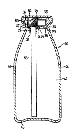
Referring to the drawings and in particular figures 1, 3 and 4 a
stopper of the present invention is shown generally at 30. The stopper 30
includes a generally tubular side wall 32, a bottom 34 with an aperture 36 and
at
least one vent hole 38 formed therein.
The stopper 30 is adapted to fit an individual beverage container or
bottle 40 such as those commonly used for fruit juice and the like. Typically
fruit
juice bottles are wide mouth containers made from glass, plastic or other
material. These bottles come in various shapes and sizes depending on the
manufacturer and distributors. However, many of the different shaped bottles
have necks that have the same interior dimensions and exterior dimensions.
This is likely the case so that the different shaped bottles can fit into the
same
bottling machines. Accordingly although only one shape of bottle is shown in
the
drawings herein, it will be appreciated by those skilled in the art that this
equally
applies to all shapes of bottles. Further, it will be appreciated that a
stopper of
the present invention will ~t into different shaped bottles that have the same
throat and neck dimensions.
_g_
CA 02332611 2000-11-15
WO 99/59893 PCT/CA99/00400
Bottle 40 has an interior volume 42 which is defined by the exterior
walls 44. The exterior walls 44 include side walls 46, a bottom 48, a neck 50
and
a mouth 52. Typically the inner diameter of the neck 50 is either conical or
decreases slightly downwardly from the mouth 52 in a frustoconical shape and
then increases to the diameter of the side walls 46. A cap 54 (shown in figure
1 ) of metal, plastic or other material is attachable to the neck 50 to seal
bottle 40
and to cover the mouth 52. Typically the cap 54 is attachable to the bottle by
a
threaded type closure or a pressure type closure. A threaded type closure 56
is
shown in figures 3 and 4. Similarly, a threaded type closure is shown in
figures
11 &12 wherein the neck is provided with threads 57 over which a cap may be
attached. Alternatively a rim (not shown) is provided over which a cap may be
attached through a pressure fit.
A straw 58 may be used in conjunction with the stopper of the
present invention. Referring to figure 2, preferably the straw 58 includes an
elongate portion 60, short portion 62 and a corrugate portion 64 therebetween.
The corrugate portion 64 allows for extension and compression of the straw 58.
In addition it allows for flexible manipulation of the straw and in particular
of short
portion 62. Short portion 62 is dimensioned such that the straw can have a
closed or stowed position as best seen in figures 1 and 3. Elongate portion 60
of
the straw 58 is dimensioned such that it reaches to the bottom of the bottle
40,
as shown in figure 1.
Generally tubular side wall 32 of the stopper 30 is adapted to be
positioned in the neck 50 of bottle 40 and to fit snugly therein. Side wall 32
may
have a number of different configurations to ensure that it fits snugly
therein,
some examples of which will be described below. It is important that stopper
30
has enough structural integrity so that once it is positioned in the neck 50
of
bottle 40 it is not easily removed.
Referring to figures 1, 5, 6 and 7 stopper 30 has a generally
tubular side wall 32 which has a slight inward angle so as to facilitate the
positioning of stopper 30 in the neck 50 of bottle 40. The stopper shown in
figures 1,5, 6 and 7 is made of thin material and in order to provide the
stopper
-10-
CA 02332611 2000-11-15
WO 99/59893 PCT/CA99/00400
with enough rigidity a pair of ribs or webs 65 are formed therein. Each rib 65
is
shaped such that a peripheral edge 67 is spaced inwardly from the side wall 32
and a peripheral trough 66 is formed therebetween. Each rib 65 has an inner
wall 68 that is spaced from the inner wall of the adjacent rib such that a
channel
70 is formed therebetween. Preferably, channel 70 has a curved shape such
that when the corrugate portion 64 and the short portion 62 of the straw 58
are
positioned in the stopper 30 and they are in the closed position they fit
freely
therein as shown in figures 1 and 3. The bottom of trough 66 forms a circular
inside surface 71. During the assembly process a cylindrical pressing tool may
be used which bears on cylindrical inside surface 71.
Referring to figures 1 and 5, stopper 30 is designed to withstand
some compression forces that will be applied during the assembly process. A
fold 149 is formed between bottom 34 and side wall 32 to isolate bottom 34
from
side wall 32. The fold 149 is an extension of trough 66. Therefore when radial
compression force is applied to the side walls 32 the fold 149 will absorb the
force by deforming or by the side walls sloping inwardly and thereby the
bottom
34 is less likely to buckle. If no fold 149 was formed between bottom 34 and
side
wall 32 , a radial compression force of sufficient strength would cause the
bottom
34 to buckle.
Referring to figures 1 and 6, aperture 36 of stopper 30, in this
embodiment, is adapted to receive a straw 58 (not shown in figure 6). A sleeve
72 extends upwardly from the drinking aperture 36 and downwardly from
channel 70 and is positioned proximate to the side wall 32. Preferably sleeve
72
is as close to the side wall as practicable so that when the straw 58 is
positioned
therein the short portion 62 thereof is as long as possible. Sleeve 72 is
adapted
to receive straw 58. Sleeve 72 provides support to straw 58 once placed in
aperture 36. Aperture 36 in stopper 30 may be a circular hole, an "X" or the
like
whereby straw 58 may be easily inserted therethrough. Sleeve 72 is adapted to
hold straw 58 in position during repeated manipulation of straw 58 from the in
use to stowed position.
Channel 70 is configured such that it is generally a "U" shape
-11-
CA 02332611 2000-11-15
WO 99/59893 PCT/CA99/00400
between ribs 65. Ribs 65 add rigidity to stopper 30. Radius 74, best seen in
figure 1, between the sleeve 72 and the channel 70 in the stopper 30 reflects
the
shape of the corrugate portion 64 of the straw 58 when in the bent position.
Ribs
65, on the side opposite aperture 36, may have a portion bent away from each
other, as shown at 61 in figure 9, or be sloped toward the bottom 34, as shown
at
63 in figure 8, to provide easy access to the top of short portion 62 of the
straw
58. Thereby the user may easily move the straw 58 from the stowed to the
drinking position.
Vent hole 38 is provided in stopper 30 to allow, upon removal of
cap 54, air to pass through the stopper 30 and equalize the pressure above and
below the stopper 30 positioned in bottle 40. This is particularly important
with
carbonated beverages wherein on opening the cap carbon dioxide gas will
escape from the interior volume 42 of the container 40 through vent hole 38
rather than through the straw 58. The vent hole 38 should be of size and
number
sufficient to allow the beverage to drain or flow into the interior volume 42
of the
container 40 should beverage be present above the stopper 30. Alternatively,
if
the fit between the stopper 30 and straw 58 is loose enough to allow some
liquid
therebetween but tight enough to hold the straw 58 in position, vent hole 38
can
be eliminated.
Referring to figure 7, a remove tab 76 may be formed into the side
wall 32 of the stopper 30 and folded down so that it will not interfere with
the cap
54 being positioned on the bottle 40. Remove tab 76 provides a mechanism to
allow easy removal of the stopper 30 and straw 58 from bottle 40, if desired
by
the consumer.
Stow tabs 78, shown in figure 7, may be formed in the ribs 65 of the
stopper 30 for the purpose of keeping the straw 58 in the stowed position.
Stow
tabs 78 are resiliently deformable such that upon manipulation of the straw
58,
the straw may be moved from the stowed position to the in use position and
vice
versa.
The upper edge 80 of the side wall 32 of the stopper 30 should not
be of a shape so as to interfere with the sealing capacity of cap 54.
-12-
CA 02332611 2000-11-15
WO 99/59$93 PCT/CA99/00400
Each rib 65 has a flat portion 82 that will accept a removable tag or
patch 84 with adhesive on the side thereof, as shown in figure 3. Tag 84 is
removably attached to the flat portions 82 of ribs 65. Tag 84 may also be
attached to the top of short portion fit of straw 58 in the stowed position.
Tag 84
has a pull tab 86. Thus when the user pulls tab 86 tag 84 will disengage from
ribs 65 and pull straw 58 from the stowed position to the in use position.
Alternatively, as shown in figure 9, rather than providing pull tab 86 the
ribs 65
may be provided with indentations or dimples 85 to provide a place where a
user
may grip tag 84 and remove it from the ribs 65. It will be appreciated by
those
skilled in the art that tag 84 may have printed matter thereon thus providing
a
number of opportunities in the marketing of the product. Advertising or other
contest type information could be printed on both sides of tag 84. The
adhesive
used on tag 84 may be of the type that allows removal and replacing. Thus tag
84 could be used in a variety of promotional campaigns, for example the
consumer has to collect a number of tags to spell a word. Tag 84 will also
keep
straw 58 in the stowed position during the automated assembly process when
the stopper/straw/tag combination is positioned in bottle 40.
Referring to figure 5, alternatively the stopper 30 of the present
invention could be used in conjunction with a generally available straight
straw
88. Straight straw 88 is made of a material that allows it to be kinked into a
roughly right angle configuration and kept in that position without permanent
deformation to its cylindrical nature.
Alternatively, as illustrated in figure 10, a stopper 90 may be made
of a thick wall-type material such as plastic foam or the like. Stopper 90
functions similarly to stopper 30 and has similar features. Stopper 90 has
side
walls 92 and a bottom 94 that has an aperture 96 formed therein for receiving
a
straw. A sleeve 98 extends downwardly from aperture 96 and is formed by the
thick wall material. A channel 100 is contiguous with aperture 96 and provides
a
place for an upper portion of a straw. A vent hole 102 is formed in bottom 94.
Flat portions 104 are formed of the thick wall material.
Figures 11 and 12 show a stopper 106 for a drinking straw 108,
-13-
CA 02332611 2000-11-15
WO 99/59893 PCT/CA99I00400
similar to drinking straw 58, that is adapted for use in a regular mouth "pop"
bottle
110 with neck 112. Stopper 106 is similar to stopper 30 described above.
Stopper 106 includes a generally tubular side wall 114, an aperture 116, a
sleeve
118, vent holes 120 and a bottom 122. A removable pull tag 124 is attached to
the upper portion of straw 108 to pull the straw from the stowed compressed
position to the in use position.
Figure 13 and 14 show stoppers of the present invention which are
adapted to facilitate drinking directly from the bottle so that the user need
not put
the entire mouth of the bottle into their mouth before drinking. Figure 13
shows a
thin walled stopper 125 which includes a generally tubular side wall 126, a
raised
flat portion 128, and a sloped portion 130. An aperture 132 is formed in
raised
flat portion 128 which is large enough to allow a user to drink therethrough.
A
vent hole 134 is formed at the lower end of the sloped portion 130. The vent
hole
134 allows air to enter the bottle 40 as beverage is allowed to exit the
aperture
132 while also providing a means for beverage that may be present in the
stopper to drain back into the bottle. The side wall 126 of the stopper 125
would
serve the same purpose as the side wall 32 of the stopper 30.
Similarly, figure 14 shows a thick walled stopper 136 made from
plastic foam or the like. Stopper 136 is similar to stopper 125 but made from
different material. Stopper 136 has a side wall 138, a flat portion 140 and a
sloped portion 142. A semi-circular aperture 144 is formed in side wall 138 to
provide a drinking opening when stopper 136 is positioned in a bottle. A small
aperture 146 is formed in the side wall 138 adjacent to the lower end of the
sloped portion 142 to provide a vent hole when stopper 136 is positioned in a
bottle.
Stoppers 125 and 136 are adapted for drinking through aperture
132 and portion 144. These are dimensioned and shaped to allow for a
satisfactory flow of beverage to the user and, alternatively, be able to
accept
through the drinking opening a straw or straws provided by the user, thereby
allowing consumption of the beverage through drinking straws with the stopper
still in place in the interior of the neck of the container.
- 14-
CA 02332611 2000-11-15
WO 99/59893 PCT/CA99/00400
The stopper of the present invention may have a number of
different side wall configurations. Many such configurations are shown in
figures
15 to 23. Each configuration is such that the stopper may be positioned in
bottle
40 with a friction or press fit. Each side wall configuration incorporates
some
flexibility such that the stopper can be positioned in necks within a
predetermined
tolerance range. Figure 15 shows a barrel shaped side wall 150. Figure 16
shows a polygon shaped side wall 152. Figure 17 shows a saw tooth shaped
side wall 154. Figure 18 shows a segmented side wall 156. Figure 19 shows a
stepped side wall 158. Figure 20 shows an outwardly ridged sloped side wall
160. Figure 21 shows an inwardly ridged sloped side wall 162. Figure 22 shows
a side wall that is a generally straight side wall 164 with an annular ring or
wiper
edge 166 formed therein. The annular ring 166 may be positioned at the lower
edge of the side wall, to squeegee beverage from the interior of the neck 50
of a
container 40 during automated assembly of the stopper/strawltag assembly into
bottle 40. Figure 23 shows a side wall having a textured surface 168. The
textured surface 168 would allow the stopper to grip the neck of the bottle
even if
during the bottling process the inside surface of the bottle is "wet" since
the
textured surface would provide a path for the liquid to flow into the interior
volume
42.
Referring to figure 26, as a further alternative the stopper 190 and
straw 192 could be integrally attached as shown generally at 194. Similar to
the
above stoppers the unitary stopper/holder 194 would have a press fit and thus
would have the features of one of the stoppers described above. Further, as
described above the straw 192 can be manufactured with or without corrugations
as chosen by the manufacturer. The straw 192 would be flexible such that if on
installation the straw would touch the bottom of the bottle the straw would
flex so
that the stopper/holder 194 could still fit tightly into the bottle.
Straw 192 has a bevelled end 196 to minimize the chance of the
user sucking on the straw such that it sticks to the bottom of the bottle and
no
liquid can enter therein.
Preferably the stopper 30 of the present invention is manufactured
-15-
CA 02332611 2000-11-15
WO 99/59893 PCT/CA99/00400
by way of injection molding. There are a number of features of stopper 30 that
make it adaptable to an injection molding process. Particularly stopper 30 has
a
uniform wall thickness and a thin wall design. In addition, as discussed
above,
the side wall 32 and alternate side walls shown in the drawings are angled
slightly inwardly from the upper edge to the lower edge. The angled side walls
allow the stopper to easily be released from the mold in the injection molding
process. The uniform wall thickness makes it easier to mold in the injection
molding process. The thin wall design keeps the cost of material as low as
possible. In addition the thin wall design keeps the cost of manufacturing low
since it only requires a short cycle time.
An alternate use for the stopper of the present invention is shown in
figure 24 and 25 wherein a stopper 170 is positioned in a gable top carton
172.
Stopper 170 includes most of the features described above with regard to
stopper 30. Further the different side wall configurations described above
would
be equally applicable to stopper 170. Stopper 170 is positioned in a side pour
spout or neck 174. A straw 184 is positioned in stopper 170. A tag or patch
186
is used to hold straw 184 in place and to seal the neck 174.
The side pour spout or neck 174 is generally cylindrical and has a
flange 176, a threaded neck 178 and top 180. Flange 176 is attached to a
sloped gable portion 182 of carton 172. As can be seen in the figures 24 and
25, stopper 170 is not coaxially aligned in carton 172 and therefore straw 184
positioned therein is not coaxially aligned. To allow the user to easily move
the
straw around the bottom of the carton sleeve 72 of stopper 30 is eliminated or
modified.
Referring to figure 25, the stopper 170 is positioned in neck 174.
Straw 184 is positioned in stopper 170. Patch 186 is attached to stopper 170
or
neck 174.
Assembly of the stopper 170, straw 184 and patch 186 in the neck 174 could
occur either before or after the neck 174 is attached to the carton 172.
Stopper
170 could be positioned in any rotational attitude, either with the trough 188
being horizontal, as in figures 24 and 25 or sloped, with the straw hole 190
either
-16-
CA 02332611 2000-11-15
WO 99/59893 PCT/CA99/00400
proximate to the upper or lower edge of the neck 174. The tag or patch 186
would attach to the rim of the neck 174 so as to provide a seal. Typically
gable
top cartons with necks currently have a similar type seal.
It will be appreciated that the above description related to one
embodiment by way of example only. Many variations on the invention will be
obvious to those skilled in the art and such obvious variations are within the
scope of the invention as described herein whether or not expressly described.
-17-