Note: Descriptions are shown in the official language in which they were submitted.
CA 02332838 2000-11-17
WO 99/60227 PG"T/US99/11104
-1-
Handrail/Leaning Rail
=al Field
The present invention relates to handrails and, in
particular, to a handrail that is configured to enable
infirm persons to either grasp it or lean on it for
support and to prevent any part of a user's hand or arm
from passing through a space between a handgrip portion
and the wall to a position below the handgrip portion,
should the user lose his or her grip on the handgrip
portion.
Hospitals, nursing homes and assisted-living
facilities make extensive use of handrails so that infirm
persons have something to hold onto when they walk from
place to place. The handrails are often designed not
only for providing support to infirm persons but for
protecting the walls from impacts by food carts,
equipment carts, litters and other objects that are moved
through the building. As far as the present applicants
are aware, all handrail systems commonly used in
hospitals and nursing homes have rails that are maunted
on brackets that. are spaced apart along the'wall and
support the rails some distance from the wall, thus
leaving a gap beaween the wall and the rail. The gap is
usually wide enough to accept the hand and forearm of a
person. It is, therefore, possible for a user's hand to
accidently slip from grasping engagement with the
handgrip and pa:as through the gap. If the person falls
CA 02332838 2000-11-17
WO 99/60227 PCT/US99/11104
-2-
while his or her arm extends into the gap between the
handrail and the wall, his or her hand, wrist or arm can
be broken.
Some infirm persons are not physically able to get a
good grasp on the handgrip of a handrail or not able to
grasp the rail at all. Instead, they rest their hand or
lean their forearm on the rail for support. Many
previously known handrails are not well suited for being
leaned on, either because they lack a wide upper surface
:LO or the upper surface is spaced widely apart from the wall
and can uncomfortably trap or pinch the forearm of the
user between the wall and the handgrip portion of the
rail or even allow the forearm to pass between the
handgrip and the wall.
Another shortcoming of many previously known
handrails of the type used in hospitals, nursing homes
and assisted-living facilities is an "institutional" or
commercial appearance. A pleasant environment
contributes to t:he well-being of the occupants.
Attractive special functional fixtures, such as
handrails, should have a residential appearance to the
extent possible.
An object of the present invention is to provide a
rail - a "handrail/leaning rail" - that can be grasped or
leaned on for support. It is also an object to provide a
handrail/leaning rail that presents surfaces that are
free of discontinuities along the length of the rail that
can catch a user's fingers or hand. In addition, it is
CA 02332838 2000-11-17
WO 99/60227 PCT/US99/11104
-3-
desired to ensure: that a user's hand or forearm cannot
protrude though a. gap between the handgrip and the wall
and be injured. Yet another object is to protect the
wall on which the handrail/leaning rail is mounted from
impacts by objects such as food and equipment carts.
Furthermore, it is an object of the invention to provide
a handrail/leaning rail in which, preferably, the wall
surface adjacent the rail is covered by a shield portion
of the rail and the rail is attractive in appearance,
durable, economical to produce and install, and easy to
clean.
The foregoing objects are attained, in accordance
with the present invention, by a handrail/leaning rail
that includes a mounting system adapted to be attached to
1!5 a wall and an elongated rail separate from the mounting
system and removably attached to the mounting system.
The rail has a handgrip portion having a top surface and
undercut front and rear surfaces shaped for grasping by a
user, the rear surface being positioned on the rail to be
2n spaced apart from the wall. A safety blocking portion
that is longitudinally coextensive with the handgrip
portion and extends rearwardly from a lower base portion
of the rear surface of the handgrip portion substantially
blocks a gap that would otherwise exist between the lower
2!5 base portion of the handgrip portion of the rail and the
wall. In preferrE~d embodiments, the rail also has a wall
shield flange port: ion extending upwardly from the safety
blocking portion and spaced apart from the rear surface
of the handgrip portion.
CA 02332838 2000-11-17
WO 99/60227 PCT/US99/I I I04
_q_
The mounting system may consist of mounting brackets
adapted to be attached to the wall in spaced apart
relation and received under the rail. Alternatively, the
mounting system may have elongated brackets that extend
lengthwise substantially coextensively with the rail.
The elongated brackets may, for example, have a rail-
supporting flange portion that extends out from the wall
and is received either in a slot in the safety blocking
portion or in a recess in the underside of the safety
:LO blocking portion.
In preferred embodiments, the handgrip portion, the
safety blocking ;portion and, when included, the wall
shield flange portion are unitary. A unitary rail can be
made of a metal, such as aluminum, brass or stainless
L5 steel, a rigid polymeric material, such as polyvinyl
chloride ("pvc"), a rigid structural foam polymeric
material having .a solid skin, such as pvc, or wood. The
rail can be solid or hollow. It is also possible for the
rail to have a structural base or retainer and a rail
:20 cover of a rigid polymeric material, such as pvc.
Although the rail may have a textured surface, it is
preferred that t:he surface be smooth so that it is easy
to clean.
In some cases, the material of the rail is
25 inherently impact resistant and provides good protection
for the wall while retaining a good appearance after
impacts from carts an other objects. Otherwise, for
example when the rail is of wood or aluminum, the front
surface of the h,andgrip portion may have a bumper insert
CA 02332838 2000-11-17
WO 99/60227 PCT/US99/11104
-5-
of a suitable impact-resistant material, such as a rigid
or semi-rigid polymeric material.
Walls are rarely absolutely flat. In order to avoid
leaving gaps between a wall shield flange portion of the
rail and the wall, the wall shield flange may have at its
upper edge a flexible sealing lip that is adapted to
engage the wall and to conform to irregularities in the
wall. The sealing lip not only improves the appearance
of the rail as installed but closes up any gaps where
dirt can collect.
In embodiments of the present invention in which the
rail includes a 'wall shield flange portion extending
upwardly from the safety blocking portion and spaced
apart from the rear surface of the handgrip portion, the
mounting system may consist of elongated L-shaped
brackets that extend substantially coextensively with the
rail and have upper mounting flange portions received
rearwardly of the wall shield portions in rear recesses
of the wall shield portion. The upper flange portions
receive fasteners, by which the brackets are attached to
the wall. The mounting flange portions and fasteners are
completely concealed by the wall shield portions of the
rails.
The handgri;p portion of the rail can have any shape
in cross-section, such as round, rectangular with small-
radius corners, or generally oval, that allows it to be
grasped. It is ;preferred that the upper surface of the
handgrip portian be shaped and dimensioned to conform
substantially to a comfortably open palm of an
outstretched hand of a person. For example, the upper,
CA 02332838 2000-11-17
WO 99/60227 PCT/US99/11104
-6-
front and rear surfaces may form in cross-section a
portion of an ov<~1, modified to have a generally convex
upper surface. A desirable configuration for the
handgrip portion is an oval with a slightly convex upper
surface and having a major dimension of about two inches
and a minor dimension of about one inch. The wall shield
flange portion, preferably, has an upper edge configured
to engage the wall and a smoothly convexly curved frontal
surface adjacent the upper edge. The rear surface of the
1.0 handgrip portion should be spaced apart from the upper
edge of the wall shield flange portion by about one and
one-half inches t:o leave room for a user to grasp the
rear edge with hi.s or her fingers but to prevent a user's
open palm or forearm from intruding into the space. The
1,5 forearm can, in fact, nest comfortably in the gap between
the handgrip portion and the upper curved frontal surface
of the wall shield flange.
A handrail/l.eaning rail, according to the present
invention, provides a handgrip that can be grasped by
users who are able to do so but that also can be leaned
on with an open palm or with the forearm by users who
cannot or who choose not to grasp the handrail. The
safety blocking portion of the rail prevents a user's
hand or forearm from slipping into the gap that usually
~:5 exists between previously known handrails and the wall
and also provides a longitudinally continuous uniform
surface, free from obtrusions, such as mounting brackets,
that can catch a user's fingers. By having the rail
separate from the: mounting system, it is possible to
a0 adapt rails of various materials and configurations to
CA 02332838 2000-11-17
WO 99/60227 PCTNS99/11104
the same mounting system, thus providing an architect or
designer with thE: freedom to choose an esthetically
pleasing rail sy:atem for the space in which the rail is
installed. The separate mounting system also permits
replacement of the rails, facilitates installation, and
provides the possibility of fully concealed or hidden
fasteners and, in the forms with
L-shaped brackets, fully concealed mounts for the rails.
The handrail/leaning rail of the present invention has
1.0 the appearance of: millwork, a residential look and is
durable and easy to care for. Where provided, as is
usually to be preferred, the wall shield flange portion
of the rail protects the wall adjacent the handgrip from
becoming soiled and eliminates a gap where dirt can
1.5 collect. The wall shield flange portion is easy to keep
clean, as compared to many wall surfaces .
For a more complete understanding of the present
invention, and the advantages thereof, reference may be
~:0 made to the following written description of exemplary
embodiments, taken in conjunction with the accompanying
drawings.
Fig. 1 is an end cross-sectional view of a first
embodiment;
:?5 Fig. 2 is an end cross-sectional view of a second
embodiment;
Fig. 3 is an end cross-sectional view of a third
embodiment;
CA 02332838 2000-11-17
WO 99/60227 PCT/US99/11104
_g_
Fig. 4 is a fragmentary detail view of the portion
of the third embodiment indicated by the circle 4 of Fig.
3;
Fig. 5 is an end cross-sectional view of a fourth
embodiment;
Fig. 6 is an end cross-sectional view of a fifth
embodiment;
Fig. 7 is a front elevational view of an end portion
of the first thra~ugh fifth embodiments, which shows one
form of treatment of the end of a rail section;
Fig. 8 is a top plan view of an end portion of the
first to fifth embodiments, which includes the end cover
of Fig . 7 ;
Fig. 9 is a top plan view of two sections of the
first to fifth embodiments and shows one form of outside
corner;
Fig. 10 is end cross-sectional view of a sixth
embodiment;
Fig. 11 is a top plan view of two sections of the
first to sixth embodiments and shows the joint at an
inside corner;
Fig. 12 is a top plan view of two sections of the
first to sixth embodiments and shows an inside corrxer
joint and another form of end piece at the ehd of the
rail section;
Fig. 13 is an end cross-sectional view of a seventh
embodiment, in which the bracket system is based on
spaced- apart brackets;
CA 02332838 2000-11-17
WO 99/60227 PCT/US99/11104
_g_
Fig. 14 is a front elevational view of an end
portion of the seventh embodiment and shows one form of
end piece for the. end of a rail section;
Fig. 15 is <~ front elevational view of an end
portion of the seventh embodiment and shows another form
of end piece;
Fig. 16 is an end cross-sectional view of an eighth
embodiment;
Fig. 17 is an end cross-sectional view of a ninth
7. 0 embodiment ;
Fig. 18 is an end cross-sectional view of a tenth
embodiment;
Fig. 19 is an end cross-sectional view of an
eleventh embodiment; and
7.5 Fig. 20 is an end cross-sectional view of a twelfth
embodiment.
In most instances, corresponding parts and portions
of all of the embodiments are assigned ref erence numerals
having the same 7.ast two digits.
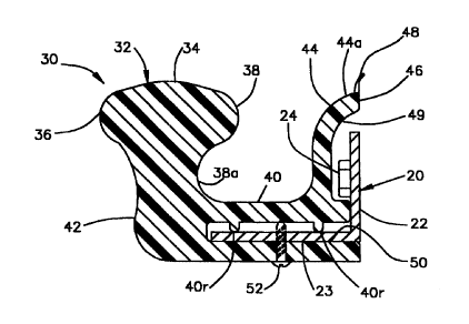
The first embodiment, shown in Fig. 1, has an
elongated mounting bracket 20 of uniform cross section
along its length,. The bracket 20 is, preferably, of
metal, such as a7~.uminum or steel (a standard steel angle
:?5 profile is possible), and has an upper mounting flange
portion 22 that receives, for example, toggle bolts 24
that pass through a drywall into steel studs (not shown)
or any suitable f=astener by which a rail 30 is mounted on
a wall. The rail. 30 is of uniform cross-section along
CA 02332838 2000-11-17
WO 99/60227 PCT/US99/11104
-10-
its length and has a handgrip portion 32 having an upper
surface 34, an undercut front surface 36, and an undercut
rear surface 38. The handgrip portion may be of any
shape that is suitable for grasping. An oval-shape in
cross section is preferred. The upper surface in the
embodiment is sl.ightly.convexly curved, a shape that
allows a comfortably open palm of an outstretched hand of
a user who chooses to lean on the rail rather than grasp
it to rest on this top surface. The curvature helps
a0 stabilize the user's hand against slipping off. The
handgrip can be about two inches wide and one inch high.
A safety blocking portion 40 that is longitudinally
coextensive with the handgrip portion extends toward the
wall from the baae 38a of the rear surface 38 of the
:L5 handgrip portion 32. The blocking portion closes the gap
that would otherwise exist between the handgrip portion
and the wall, thereby preventing a user's hand or forearm
from passing between the handgrip portion and the wall.
It also presents a smooth, continuous surface, and
:ZO eliminates any obstructions or :irregularities along the
rail on which a user's fingers might get caught. The
frontal surface 42 below the handgrip portion and at the
(rant of the safety blocking portion is smoothly
contoured, preferably avoiding sharp corners, to provide
.25 both good function and appearance.
A wall shield flange portion 44 extends upwardly
from the rear portion of the safety blocking portion 40
in a position to leave a space between it and the rear
surface 38 of the handgrip portion 32 for the fingers of
30 a user who grasps or leans on the rail. The upper edge
CA 02332838 2000-11-17
WO 99/60227 PCTNS99/11104
-11-
46 of the flange: portion 44 is positioned to engage or to
be very close to the wall. A flexible sealing lip 48 is
formed with or attached to the upper edge so as to
conform to any irregularities in the wall - one form of
lip 48 is described below. The upper part of the shield
flange portion has a smoothly convexly curved front
surface 44a, which prevents discomfort to a user whose
hand or forearm engages it. The surface 44a also forms
with the surface 38 of the handgrip portion a nest in
which a user can rest his or her forearm for support.
The upper edge 46 is spaced apart from the rear extremity
of the handgrip ;portion 38 by about one and one-half
inches.
The shield flange portion 44 of the rail has a
recess 49 in its rear surface which receives and fully
conceals the mounting flange portion 22 of the bracket
20. The safety blocking portion 40 of the rail has a
longitudinally continuous slot 50 that opens at the rear
edge and receive;s and fully conceals a rail-supporting
.20 flange portion 2:3 of the bracket 20. Ribs 40r protrude
into the slot and allow tolerance and alignment
variations to occur without causing binding between the
flange portion 2:3 and the slot 50. Screws 52, which are
preferably self-tapping, that pass through the blocking
portion 40 below the slot 50 and thread into the
supporting flanges portion 23 of the bracket 20 secure the
rail 30 to the bracket 20. The screws are generally
hidden from view and can, of course, be removed to permit
replacement of the rail.
CA 02332838 2000-11-17
WO 99/60227 PCT/US99/11104
-12-
The rail 30 can be made of a metal, such as
aluminum, brass, or stainless steel, a rigid polymeric
material, such a.s a pvc extruded profile, a structural
rigid foam polymeric material with a solid shell, such as
an extruded pvc foam, or wood. An architect has
considerable freedom to choose among possible materials
for the rail.
The embodiment of Fig. 2 is for the most part the
same as that of Fig. 1, and the reference numerals in
Fig. 2 are the same of those of Fig. 1, but increased by
100. The only difference is that the rail 130 is hollow.
The third embodiment - Fig. 3, 200 series reference
numerals applied - has a bumper insert 260 affixed to the
front surface 236 of the handgrip portion 232 of the rail
230. The bumper insert is pre-formed of any suitable
impact/mar-resistant material, which may be a rigid or
semi-rigid polymeric material, such as pvc. The bumper
insert is optional but is preferred if the rail is made
of a material, such as wood, which can be marred or
damaged by impacts. The bumper insert 260 is
longitudinally coextensive with the rail 230 and has a
serrated stem portion 260s that is received in a groove
in the rail in an interference fit relationship. If
desired or if necessary for secure affixation, an
adhesive can be 'used to attach the bumper insert 260 to
the handgrip partion of the rail.
In the embodiment of Fig. 3, the rail-supporting
flange 223 of the bracket 220 has ribs 223r that allow
for tolerance and alignment variations - the ribs 223r
are functionally equivalent to the ribs 40r of the first
CA 02332838 2000-11-17
WO 99/60227 PCT/US99/11104
-13-
and second embodiments. The ribs 40r and 223r can, of
course, be relocated to the underside of the slot or
bracket.
Fig. 4 shows in detail a flexible sealing lip 248
which is prefornned by extrusion of a semi-rigid polymeric
material, such a.s pvc, and press-fitted into a groove in
the upper edge portion of the wall shield flange portion
230. It is possible to form a sealing lip integrally
with a rail of polymeric material. The sealing lip
deforms elastically so as to conform with an irregular
wall surface - most walls are not absolutely planar.
With some walls, such as masonry walls, an adhesive caulk
can be applied at the juncture of the upper edge of the
wall shield flange portion of the rail with the wall.
Some form of seal at that juncture is desirable to seal a
gap where dirt and bacteria can otherwise intrude and be
trapped.
Fig. 5 shows a rail 530 like that of Fig. 3 but made
hollow. Rails of either solid or foamed polymeric
materials or of extruded metal can be hollow in order to
save material costs.
A suitable variation of the rail, shown in Fig. 6,
is a rail having a recess 650 on the undersurface of the
safety blocking portion 640. The rail 630 ~is mounted
entirely on top of the supporting flange portion 23 of
the bracket 20. The bracket cannot easily be seen, even
though it is exposed on the underside of the rail. The
screws 52 pass through the bracket and thread into the
rail.
CA 02332838 2000-11-17
WO 99/60227 PCT/US99/11104
-14-
Like all good things, rails must come to an end,
such as at door openings. Figs. 7 and 8 show one form of
treatment of the: end of a rail section, namely, a molded
or milled end piece 80 which is arcuate in plan rFig. 8),
has a cross-section along the arc that matches that of
the rail 30, and. has a planar ~f ree end 80e that engages
or lies very close to the wall on which the rail is
mounted. There are many ways of joining the end piece 80
to the rail 30. Also, the rail-supporting flange 23 of
the bracket 20 can be extended to be received in a slot
in the end piece or a recess on the underside of the end
piece and screws used to fasten the end piece to the
bracket.
As shown in Fig. 9, the end piece 80 can also be
used at an outside corner where two sections of rail 30
on the intersecting walls meet.
The rail can be made of two or more pieces, which
can yield cost-savings - due, for example, to waste
material milled .away - without significantly impairing
the function or appearance of the rail. A very simple
structure is shown in Fig. 10. The mounting assembly is
a metal angle 10:20. The rail 1030 consists of a handgrip
member 1032 and ;a safety blocking member 1040, a flange
portion 1044 of which serves as a wall shield flange
portion. A portion along the front edge of the blocking
member 1040 is received and captured in a groove 10308
along the base o:E the handgrip member. The rail-
supporting flange portion 1023 of the bracket 1020 is
received in a recess 1050 on the undersurface of the
handgrip member :1030, which is fastened to the flange
CA 02332838 2000-11-17
WO 99/60227 PCT/US99/11104
-15-
portion 1023 by countersunk screws 1052 that thread into
the handgrip member. The rail of Fig. 10 presents the
interesting possibility of making the handgrip and the
blocking members of different materials. The bracket and
fasteners are well-hidden from view. The modified shape
of the handgrip portion - flat upper surface 1034 - and
the shorter shield flange portion 1044 are indicative of
various changes in the shape of the rail that are
possible. The rail of Fig. 10 can be grasped or leaned
on; the gap between the handgrip portion and the wall is
blocked; the rail is easily cleaned, has a good
appearance, includes a concealed bracket and concealed
fasteners, and is inexpensive.
Figs. 11 and 12 show an inside corner joint between
rail sections mounted on walls that intersect. It is
simply a mitered joint, formed by cutting the ends of the
rails 30 at 45 degree angles to their axes. Note that
the brackets 20 ~can - but need not - end short of the
joint. Fig. 12 :reveals that it is desirable to form butt
:ZO joints 20j between brackets 20 in a long rail section at
a location spaced apart from a butt joint 30j between
rail sections. 'The respective joints should not
coincide. Fig. :12 also shows a treatment of the end of a
rail section that is formed by cutting off the end of the
rail 30 at an angle, such as 45 degrees, and affixing an
end piece 90 in the form of a plate having a perimeter
that matches the profile of the cut off cross-section at
the end of the rail. (Fig. 14 shows the end piece 90 in
elevation.)
CA 02332838 2000-11-17
WO 99/60227 PCT/US99/11104
-16-
Another suitable mounting system for
handrail/leaning rails embodying the present invention is
based on spaced- apart mounting brackets 1420, such as
the one shown in Figs. 13 and 14. Brackets of the type
of Figs. 13 and :14 are usually molded from a durable
solid polymeric material, such as pvc. The bracket 1420
has a relative large mounting base 1422 so as to spread
the load over the wall surface that it engages, a
mounting hole l4aOmh for a bolt by which the bracket is
:l0 fastened to the wall, and a rail-fastening hole 1420fh
for a screw 1452 by which the rail 1430 is fastened to
the bracket 1430.. The holes are accessible through a
recess 1420g that: opens frontally and inferiorly, which
can either be lei_t open or covered by a press-fit or
:l5 snap-fit beauty plug (not shown). The exterior surface
of the bracket can be of any desired shape as a matter of
good appearance.
The rail 1430 of Fig. 13 is essentially the same as
the one shown in Fig. 1, except that it does not have a
a0 recess in the rearward face or a slot for the a rail-
supporting flange of a bracket 20. A groove 1430gr on
the undersurface accepts a rib 1420r on the bracket. An
integral sealing rib or a sealing rib insert 1448 seals
any gaps between the rail and the wall. -
:Z5 As mentioned above, the end of a rail section, such
as the rail 1430 of Fig. 13, can be cut off at an angle
to the lengthwise: axis and covered by an end plate 90
(Fig. 14) or cut off perpendicular to the lengthwise axis
and covered by a curved molded or milled end piece 1480
:30 (Fig. 15), which can also be used at an outside corner
CA 02332838 2000-11-17
WO 99/60227 PCT/US99/11104
-17-
(see Fig. 9). Inside corners between the rails 1430 can
have mitred joints (see Figs. 11 and 12).
The embodiment of Fig. 16 is the same as that of
Fig. 13, except that it has a bumper 1660 installed on
the front surface of the rail 1630. A similar rail 1730,
but hollow, is possible (Fig. 17).
Looking next at Fig. 18, a rail 1830 can also be
composed of a structural base or retainer 1830r of
extruded aluminum and a cover 1830r of a rigid, impact
resistant polymeric material, such as pvc, which snaps on
over the retainer and is retained by its resiliency.
Rails and other wall protection products of that
construction are known per se, such as the ACROVYN~ wall
protection products of Construction Specialties, Inc.,
the assignee of 'the present invention. Screw bosses
1830b-1 and 18301b-2 on the retainer allow for attachment
of end pieces and corner pieces (not shown). The rail
1830 is designed for use with spaced-apart brackets 1420
received under tine rail. A similar rail 1930, shown in
Fig. 19, is desi~~ned for use with continuous elongated L-
shaped mounting lbrackets 1920.
The twelfth embodiment (Fig. 20) has a two piece
rail 2030 that i;s supported on a longitudinally
continuous L-shaped mounting bracket 2020, the rail-
supporting flange 2023 of which is recessed into the
underside of the rail 2030. A tongue 2030t on the lower
front edge of a piece 2030-2 of the rail that forms a
rear part of the safety blocking portion 2040 and the
wall shield flan~~e portion 2044 is captured in a notch
2030n of the handgrip piece 2030-1 of the rail 2030. The
CA 02332838 2000-11-17
WO 99/60227 PCT/US99/11104
-18-
upper rear edge of the piece 2030-2 rests on the upper
edge of the bracket 2020. The rail 2030 of the twelfth
embodiment is well-suited for manufacture of wood.
It is possible, though perhaps a little less
desirable than other possible arrangements because of a
relatively sharp edge, to have mitred joints at an
outside corner in all embodiments of the invention. An
outside corner c<~n also be treated by having beveled ends
on the rails and cover plates (e.g., 90) concealing the
ends. Rails of solid materials (solid metal, wood or
plastic) that are. not hollow and are mounted on spaced
apart brackets ( e~ . g . the rail of Fig . 13 ) can have
beveled or rounded ends, which need not be covered.