Note: Descriptions are shown in the official language in which they were submitted.
CA 02333140 2000-11-24
1
Electronic Lock With Mechanical Clutch
Technical Field
s The present invention concerns an electronic lock able to be
unlocked by a key having a right of access recognised by an
identification code.
Background art
io At the current moment, most of the conventional or safety locks
available on the market are mechanical locks. However, there are
certain locks, namely electromechanical locks, which match
conventional mechanical coding (resulting from the profile often
produced from the blade of the key) with an electronic coding.
is Furthermore, the patent US 4 856 310 describes another type of
lock, known as an elecaronic lock able to be locked and unlocked from
comparing an identification code present in both the lock and the key
without it being necessary to add to it any additional mechanical
coding. However, this type of lock, which is fully electronic, is still not
2o available on the market, and in fact there are good reasons for this,
namely that it still has a number of particularly significant drawbacks
which in practice prevents it from being commercialised. First of all, if
for example the key is lost, it proves to be impossible to modify the
identification, codes without contacting the manufacturer of the lock. In
2s addition, the feeding of these locks with energy is assumed to be
effected by batteries which constitutes a problem having regard to their
limited periods of life. Finally, the internal structure of these locks and
in particular their barrel is still particularly complex (as often merely
adapted from conventional mechanical locks) and especially less
3o reliable as shown by the structure of the barrel (basically from several
springs compressed in the rest position) of said patent.
The first two problems have fortunately been resolved. In fact,
with the European patent application EP-A-805 906, the Luxembourg
company Electronic key systems (EKS) limited has resolved the
3s problem of modifying the identification code of the lock by adding
programming means i:o the key enabling the user to directly carry out
CA 02333140 2000-11-24
2
this modification. Similarly, the feeding with energy problem was also
resolved shortly afterwards by the international PCT patent application
WO 97/48867 filed in the name of this same company which proposed
sing a key having autonomous energy generation means. Thus, it
s merely remains to currently find for these electronic locks a simple
barrel structure to finally, and contrary to all expectations, enable these
locks to be commercialised.
Object and definition of the invention
io Thus, the object of the present invention is to provide an
electronic barrel with a simple structure adapted to an electronic
environment and comprising in particular an extremely limited number
of internal parts. OnE~ aim of the invention is also to provide a
particularly reliable (aturdy) and high-performance barrel with a
Is reduced energy consumption. A further aim is to obtain a barrel fully
protected from impact:>, vibrations or dust. Again, another aim of the
invention is to produce a barrel resistant to tearing, sinking in or picking
(anti forcible entry protection). Another aim is also to be able to easily
manage key conflicts.
2o These aims care be obtained by providing an electronic barrel
comprising a barrel body and a rotary-lock key bit, the barrel body
comprising at least one rotor having a common axis with the body and
the rotary-lock key bit and freely rotating inside said body, a clutch part
coupled in rotation witlh the rotor and comprising meshing means co-
ts operating with additional means of the key bit so as to drive in rotation
said key bit by the rotor by the action of a rotating torque of the key,
and locking means for preventing the clutch part from being translated
when there is no recognition of an identification code transmitted
between the key and the barrel, characterised in that said locking
3o means are further mounted integral in the rotary-lock key bit and in that
said rotor is mobile in translation for thrusting the clutch part towards
the key bit when said identification code is recognised.
By means of this structure with a particularly limited number of
mechanical parts, movement of the key bit can be easily effected
3s through the clutch part from the single rotation torque of the key without
control of the locking (unlocking) means requiring a great amount of
CA 02333140 2000-11-24
3
energy.
The stop of the electronic barrel is preferably constituted by a
single protection flap pivoting around an axis parallel to the axis of at
least one rotor betweein an initial position and a final freeing position.
s The protection flap acts against the action of a return spring for
automatically bringing back this flap into its initial position when the key
is removed.
The motor means preferably comprise an electric microactuator
with an axis parallel to the axis of at least one rotor, the freeing of at
io least one stop being carried out by means of a drive pinion borne by a
final drive shaft of the electric microactuator and gearing on a sector
gear integral with the stop.
The clutch part i;s formed of a cylindrical ring fitted with a central
disk and comprising on both sides of this central disk groove-shaped
is mesh means for providing linking in rotation firstly with the key bit and
secondly with the rotor. The central disk of the clutch part comprises a
central heel for co-operating with the stop for freeing this part.
According to one embodiment characteristic, the electronic
barrel further comprises at least one compression spring inserted
2o between the rotor and the clutch part. It may further comprise at least
one return clamp integral with the rotor and intended to co-operate with
the clutch part to enable it to be freed from the key bit when the key is
removed. The return clamp preferably comprises an annular disk fitted
with at least one foot traversing the clutch part and fixed to the rotor,
2s the disk co-operating with a surface of the clutch part perpendicular to
the axis of at least one rotor.
According to another embodiment characteristic, the electronic
barrel further comprises at least one circlip integral with the body of the
barrel and intended to limit the translation of at least one rotor in the
3o direction of the key bit.
Again, according to another embodiment characteristic, the
electronic barrel comprises at least one disengaging finger formed of
two independent portions spaced by a single compression spring and
intended to ensure loclking of the key in the rotor so as to enable the
3s clutch part to be freed from the rotary key bit when the key is removed.
This disengaging finger is preferably mounted perpendicular to the axis
CA 02333140 2000-11-24
4
of at least one rotor in an opening partly traversing the rotor, a first
extremity of this disengaging finger being flush inside the key pipe so
as to come into contact with an orifice of the key and a second
extremity going past the external wall of the rotor so as to come into
s contact with a longitudinal groove of the internal wall of the body of the
barrel. The groove of the internal wall of the body of the barrel may
comprise at least one slanted portion to facilitate compression of the
sole spring when the rotor is moved after the key is introduced. Thus,
the removal of the key is impossible outside an angular position
Io defined by the precise location of the groove.
The key bit preferably comprises an annular conductive track for
co-operating with a sole fixed electric contact of the body of the barrel
so as to provide it with energy from motor means. Similarly, the barrel
body comprises at least one perforation perpendicular to the axis of at
is least one rotor for receiving an electric contact, preferably of the ball
type, so as to co-operate with a corresponding conductive element of
the key. Electronic circuits placed in a cavity of the body of the barrel
and connected firstly to at least one electric ball contact and secondly
to the sole fixed electric contact are further provided so that feeding
2o from the motor means of the key bit can be effected directly from the
key through the electronic circuits.
According to a preferred embodiment, the electronic barrel of the
invention comprises a first rotor or internal rotor and a second rotor or
external rotor, and the width of the protection flap of the external rotor
2s is larger than that of the protection flap of the internal rotor so that
the
introduction of a key into the external key pipe does not allow driving of
the key bit in the presence of a key not recognised in the internal key
pipe. In this case, at least one linking barrel with a length greater than
the width of the key bit placed at the level of this key bit btween the
3o return clamps, this linking barrel being intended to co-operate with the
latter so as to prevent the simultaneous engaging of the internal and
external rotors when two keys are introduced into the two key pipes.
The invention also concerns a lock with one or two rotors fitted
with an electronic barrel as mentioned above.
Brief description of the drawings
CA 02333140 2000-11-24
s
Other characteristics and advantages of the present invention
shall appear more clearly from a reading of the following description
given by way of non-restrictive example with reference to the
accompanying drawings on which
s ~ figure 1 is an external perspective view of a barrel of an electronic lock
according to the invention,
~ figure 2 is an explodedl view showing the various internal components
of the barrel of figure 1,
~ figure 3 is a cross section of the barrel of figure 1,
io ~ figure 4 is a section along the plane IV-IV of figure 3,
~ figure 5 is a section along the plane V-V of figure 4, and
~ figure 6 is a cutaway view similar to that of figure 5, but after one
rotation of the rotor.
is Detailed description of a preferred embodiment
Figure 1 shows in external perspective an embodiment example
of a barrel of an electronic lock according to the invention. This barrel,
which conforms in sizes to a conventional mechanical double cylinder
(for example of the symmetrical European double inlet type as
2o illustrated) conventionally comprises mounted between two upstream
and downstream body portions 12, 14 an intermediate rotary locking
key bit 10 for actuating the bolt (not shown) of this lock. One of these
two upstream and dow~~nstream portions is nested inside the other, for
example with the aid of a linking finger extending from the upstream
2s body portion and fixed in a corresponding opening of the downstream
body portion (see figure 3) with the aid of any fixing elements (for
example two screws 16).
Each body portion is traversed by two half circlips 18, 20 (shown
outside the barrel) whose function is to be stated later. So as to prevent
3o any loss of these circlips, two upstream and downstream retaining rings
(not shown) can be easily forcefully mounted to cover these two body
portions of the barrel. f~owever, any other sort of means for protecting
these circlips can be used to prevent removal by providing a seal by a
weld or solder in the body portions or providing full cover by a simple
3s cap.
It shall be noted that in the initial idle position (no key) as shown,
CA 02333140 2000-11-24
6
the key bit is slightly slanted with respect to vertical.
Of course, the invention would not be limited to this sole
embodiment example of a European double cylinder type barrel and
naturally is applicable in all types of European and international barrels
s (and even possibly non-standardised models), for example in a button
single cylinder barrel or half-cylinder type barrel.
Details of the main internal parts constituting the barrel is
illustrated in an exploded view on figure 2. Starting from either of the
two upstream and downstream extremities of the barrel and being
Io directed towards its centre where the key bit is situated, this figure
shows : an upstream or downstream rotor (internal 32 and external 34
rotors respectively) in which a duct 36 (respectively 38) is made to
receive a key 8 (more :>pecifically the rod or blade of this key), a clutch
part 40 (respectively 4'~) driven by the rotor and intended to gear with
is the key bit 10, and a return clamp 44 (respectively 46) integral with the
rotor.
Placed between the two upstream and downstream clamps, that
is approximately at the level of the key bit, is a support 48 for receiving
an electric actuator, such as a micromotor 50, and which is traversed
2o by a support spindle 52 bearing fixed at each of its two extremities a
stop constituted by a protection flap 54, 56. Freeing by the pivoting of
these flaps (in the case of recognition of an identification code) is
ensured with the aid of a sector gear 58 also fixed integral with the
support spindle 52 and in gear with a drive pinion 60 borne by a final
2s drive shaft of the micromotor 50. A wound return spring 62 is mounted
on the support spindle 52 and co-operates with a spring stop 64 so as
to allow an automatic rEaurn of the protection flaps 54, 56 when the key
is removed.
Of course, this embodiment example with protection flaps
3o pivoting under the action of a rotary micromotor is in no way restrictive
and it is quite possible to provide an axial stop being freed with the aid
of a linear micromotor.
Finally, two linking barrels 66, 68 (without this number being
restrictive), whose length is larger than the width of the key bit, are
3s provided to slide on each side of the support 48 and define a minimal
distance between the upstream and downstream return clamps 44 and
CA 02333140 2000-11-24
7
46 respectively and thus prevent any simultaneous engaging of the two
rotors on the key bit 10 should two keys be simultaneously introduced
on each side of the barrel.
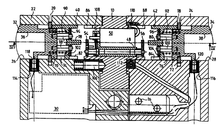
Figures 3 and 4 are sectional views of the electronic barrel of
s figure 1 which more specifically show the position of the internal parts
as illustrated on figure 2. Figure 3 is made inside the vertical plane of
symmetry of the barrel, and figure 4, which is shown with the key 8
introduced into the internal rotor, is embodied in a horizontal plane
passing through the axis of symmetry of the rotors. The locking key bit
l0 10 is shown mounted between an internal stator 22 and an external
stator 24 forming the external portions of the body of the barrel. The
internal stator is rendered integral with the external stator by a linking
finger traversed by two screws or fixing pins 16. These two stators are
each provided with a longitudinal cylindrical perforation 26, 28 having a
is common axis and in which the main internal components of the barrel
are placed. One of these stators, such as the internal stator 22, is
further fitted with a cavity to receive the electronic circuits of the barrel
30.
In the upstream portion of the barrel (the various parts described
2o hereafter are identical in the downstream portion), the internal rotor 32
(downstream reference 34) is mobile in translation in the internal stator
22 (24) between an idle position (no key present) and an opening
position limiting translation of the rotor in the direction of the key bit and
in which this rotor is in contact with the upstream circlip 18, 20.
2s At one of its two extremities, the rotor comprises the key duct 36
(38) and at the other extremity a first engaging element 70 (72) for co-
operating with a second corresponding engaging element 74 (76) of the
clutch part 40 (42). 'This clutch part, which is fitted with an axial
protuberance or central heel 78 (80) for co-operating with the freeing
3o stop, further comprises a third engaging element 82 (84) for co
operating with a fourth additional engaging element 86 (88) of the key
bit so as to have the key bit driven in rotation by the rotor under the
action of the rotation torque of the key 8. An elastic linking element,
such as a helical compression spring 90 (92) is inserted between the
3s rotor and the clutch part.
The return clamp 44 (46) is formed of an annular disk 94 (96)
CA 02333140 2000-11-24
8
fixed to at least one foat 98 (100) traversing the clutch part and whose
free extremities are for example screwed or crimped in the rotor 32
(34). The clutch part is formed of a cylindrical ring fitted with a central
disk 102 (104) and comprising on both sides of this central disk the
s engaging means 74, 8;? (76, 84) in the form of grooves to ensure the
linking in rotation firstly with the key bit and secondly with the rotor. The
central disk of the clutch part is preferably intended to co-operate with
the annular disk of the return clamp.
The key bit 10, whose positioning is ensured by a conventional
io indexing device 106 comprising an indexing finger compressing a
spring in an opening of one of the stators (for example the internal
stator 22), is also fitted with a longitudinal perforation 108 whose axis
coincides with that of l:he longitudinal perforations of the stators and
which is intended to receive the micromotor 50 and its support 48. The
is support and its motor are rendered integral with the key bit by any
fixing means (for example a screw whose passage orifice through the
support is given the reference 109 on figure 2), the support axis of the
protection flaps 54, 56 traversing this support.
It shall be observed that, so as to effectively manage the
2o conflicts of keys, the width of the external flap 56 is larger than that of
the internal flap so that the introduction into the external rotor 34 of an
unrecognised key cannot open the lock if a key is already present
(clutch part 40 engaged) in the internal rotor 32 (thus profiting from
prior recognition). Only a new recognition of this external key will tilt the
2s external flap 56 and, by provoking a forward movement of the external
clutch part 42 towards the key bit shall result in the linking barrels 66,
68 in pushing the internal clamp 44 and freeing the internal clutch part
40 so that a new engaging of the key bit by the external rotor becomes
possible, despite the presence of the key in the internal rotor.
3o The key bit also comprises an annular conductive track 110 for
co-operating with a fixed sole electric contact 112 of the barrel body so
as to allow energy feeding of the motor means 50. In order to do this,
the two portions of the barrel body each comprise a perforation 114,
116 perpendicular to the axis of the rotors and intended to receive an
3s electric contact, preferably of the ball type 118, 120, for co-operating
with a corresponding conductive element of the key 8, for example an
CA 02333140 2000-11-24
9
electric contact or conductive track 122. The various electric contacts
are interconnected through electronic circuits 30 placed in a cavity of
the body of the barrel so that feeding from the motor means of the
locking key bit can be effected directly from the key through these
s electronic circuits.
The locking of 'the key in the rotor when the latter rotates is
normally ensured by a disengaging finger whose particular structure is
shown in detail on figures 5 and 6. This extremely simple structure is
formed of two independent portions 124a, 124b ; 126a, 126b spaced by
io a single spring 128, 1:50 kept in a blind hole 132a, 132b ; 134a, 134b
pierced in each of these two portions, preferably cylindrical (the two
blind holes being opposite each other). The disengaging finger farmed
above is mounted perpendicular to the axis of the rotors in an opening
136, 138 partly traversing each rotor, a first extremity of this finger
is being flush with the key duct so as to co-operate with an orifice 140 of
this key, whereas its second extremity, by going past the external wall
of the rotor, comes into contact with a groove 142, 144 made
longitudinally in the internal wall of the corresponding stator. In this
embodiment example, which would not be restrictive, the compression
20 of the sole spring (whic:h prevents any removal of the key) made during
the movement in rotation of the rotor after the key is introduced is
rendered easier by a slanted portion of the groove of the internal wall of
the stator on which the external portion of the disengaging finger shall
slide.
2s The functioning of the double barrel illustrated is as follows. First
of all, it is assumed tf pat no key is introduced into the lock. The two
rotors are thus in a first idle position and are free in rotation. The clutch
parts are connected to the rotors but not to the key bit. In this initial
state, the protection flaps are in a first position (initial closed position)
3o in which movement of the clutch parts towards the key bit is impossible.
The key bit is kept by the indexing finger in a position offset with
respect to vertical and preferably about 30°.
When a key is introduced (for example at the level of the internal
rotor), the disengaging finger is drawn aside to allow the key to pass
3s (more specifically the blade or rod of this key) which then shall come to
a stop at the bottom of the key duct of the rotor. From this contact with
CA 02333140 2000-11-24
the bottom of the rotor, any new thrust of the key shall result in a
corresponding thrust of the rotor which shall move forward until Gaming
into contact with the half circlips. The movement of the rotor results in a
movement of the associated clutch part whilst compressing the linking
s spring and the forward movement of the return clamp integral with the
rotor ensures a movement of the linking barrels so as to prevent the
key being introduced ins the opposing rotor (in the space of the external
rotor). During these movements, the conductive track of the key is
automatically electrically connected with the ball contact of the barrel
to (several fractions of seconds suffice to ensure this linking). From this
point, an exchange of information between the key and the barrel can
be effected between the memory means of the key and those of the
barrel to obtain a recognition of the respective identification codes. If
this recognition proves to be conclusive (which means that the key has
is a right of access to the barrel), the electric micromotor is fed ensuring
via its drive pinion a pivating of the sector gear. The protection flaps tilt
by stressing the return spring and free the clutch part which, under the
effect of the expansion of the compression spring, advances towards
the key bit as soon as the opening angle of the flap permits this. This
2o movement places the clutch part in gear with the key bit which thus
only neds one rotation of the key to move. The opening torque is thus
transmitted from the rotor to the clutch part and then to the key bit by
the various mesh means (grooves) of these three components. In
addition, on starting of rotation, the key is locked inside the rotor owing
2s to locking of the resultant disengaging finger of the outlet of the groove
of the internal stator.
On removal of i:he key, the rotor returns to its initial position
under the action of thE~ disengaging finger, the return clamp bringing
the clutch part back towards the rotor. In its return travel, the clutch part
3o shall free the protection flap which shall automatically resume its initial
closed position under the action of the return spring.
The structure .described above is particularly simple and
consumes a small amount of energy. In fact, the protection flap is
automatically kept in a freed position (disengaged) by the clutch part
3s once the latter gears with the key bit. A continuous feeding of the motor
is thus not necessary and only one initial pulse for freeing this clutch
CA 02333140 2000-11-24
11
part is essential for the proper functioning of the barrel. Moreover, it
could be noted that in the illustrated version (double barrel), a single
motor ensures tilting of the two protection flaps.
s