Note: Descriptions are shown in the official language in which they were submitted.
CA 02333179 2001-07-24
CONVERGENT DEVICE, OPTICAL HEAD, OPTICAL INFORMATION
RECORDING/REPRODUCING AND OPTICAL INFORMATION
RECORDING/REPRODUCING METHOD
TECHNICAL FIELD
The invention relates to an optical head and an apparatus for optically
recording and
reproducing information to and from an optical information recording medium.
BACKGROUND ART
Optical memory technologies that use an optical disk having a pit-like pattern
as a
high density and capacity storage medium have been expanding in application,
for example, a
digital audio disk, a video disk, a document file disk, a data file, etc. In
optical memory
technology, information is recorded and reproduced to and from an optical disk
with a highly
precise and reliable light beam narrowed to a very small size. The recording
and reproducing
operation mainly depends on the optical system.
An optical head, a main component in the optical system, has the basic
functions of
convergence for forming a very small light spot of diffraction limit, focus
and tracking
control of the optical system, and detection of pit signals. These functions
are realized by
combining various optical systems and various detection techniques with
photoelectric
conversion.
An object lens used in an optical head is designed by considering plate
thickness of an
optical disk. The convergence performance of the object lens deteriorates due
to spherical
aberrations on optical disks whose thickness is different from the design
value, making
recording and reproduction difficult. Previously, a compact disc (hereinafter
referred to as
CD), a video disk, a magneto-optical disk and the like, have had a plate
thickness of 1.2 mm,
and thus one optical head can be used for recording and reproduction for all
of these optical
disks.
CA 02333179 2001-07-24
2
Recently, a high density and capacity optical disk, called DVD (digital video
disk),
has been used practically. The DVD has a smaller pit size on an information
recording plane
in order to increase recording density, relative to the CD. Therefore, for an
optical head used
for recording and reproduction of DVDs a light source wavelength and
converging lens
numerical aperture (hereinafter referred to also as NA) that determine the
spot size are
different from their CD counterparts. In order to increase recording density,
the DVD adopts
a large object lens numerical aperture. When the object lens numerical
aperture is increased,
optical resolution is improved and recording density is increased. On the
other hand, the
converged light spot has coma aberration caused by an inclination of the
optical disk. In
order to decrease the influence of coma aberration, even when the object lens
numerical
aperture is increased, the DVD plate thickness is decreased to 0.6 mm.
However, when the
DVD plate thickness is decreased, an object lens used for the DVD cannot be
used for a prior
art optical disk, thus the compatibility between the DVD and the prior art
optical disk cannot
be realized.
1 S It is to be noted that for CD the light source wavelength is about 0.78
~,rn and NA is
about 0.45, while for DVD the light source wavelength is about 0.63 to 0.65
~,m and NA is
about 0.6. Therefore, when two types of optical disks, CD and DVD, are
recorded or
reproduced by a single optical disk drive, an optical head needs two optical
systems. On the
other hand, there is a tendency to use a common optical system for CD and for
DVD in order
to make the drive compact and reduce cost. For example, a single light source
for DVD may
be used while two converging lenses for CD and for DVD are used.
Alternatively, only one
converging lens may be present for both CD and DVD while the numerical
aperture thereof is
changed mechanically or optically between the NA for CD and for DVD.
In an example of an optical system of an optical head in a CD and DVD
compatible
drive, an object lens of numerical aperture 0.6 is used as the converging
lens. In the object
lens, a central portion of numerical aperture equal to or smaller than 0.37 is
designed to make
aberration minimum when light is converged through a transparent flat plate of
thickness
CA 02333179 2001-07-24
3
0.9 mm, while an outer portion of numerical aperture equal to or larger than
0.37 is designed
to make aberration minimum when light is converged through a transparent flat
plate of
thickness 0.6 mm. A light beam of wavelength 650 nm emitted by a laser diode
is collimated
by a condenser lens to become a collimated light beam and is incident on the
object lens.
When a DVD is reproduced, the light beam narrowed by the object lens forms a
light spot on
an information plane in a DVD of thickness 0.6 mm, while it forms a light spot
on an
information plane in a CD of thickness 1.2 mm. Next, the light reflected from
the optical
disk is condensed again by the object lens and detected by a photodetector.
The
photodetector is constructed such that a focus control signal is detected by
astigmatism
technique and that a tracking control signal is detected by a phase difference
or push-pull
technique.
By using the optical head, when a CD is reproduced the light beam transmitting
the
central portion of the object lens is reflected by the medium plane and enters
the
photodetector, while the light beam transmitting the outer portion is diverged
due to large
spherical aberration and does not enter the photo-receiving plane of the
photodetector. Thus,
the numerical aperture is limited substantially to 0.37. On the other hand,
when a DVD is
reproduced the light beam transmitting the central portion is synthesized with
that
transmitting the outer portion to form a light spot. Substantially, all of the
reflected light
enters the photodetector, and reproduction is performed with numerical
aperture 0.6.
However, because the prior art optical head obtains the compatibility between
CD and
DVD by using a light source of wavelength 650 nm sufficient signals cannot be
obtained
from an optical disk having wavelength dependence due to difference in
reflectivity. This is
evident, for example, for a CD-R standardized as a rewritable CD. In the
standard of CD-R,
the reflectivity is defined to be 65 % or higher in wavelength range of 775 to
820 nm, but it
decreases at wavelengths outside the above range and the absorptivity
increases. For
example, the reflectivity decreases to 1/8 times and the absorptivity
increases to 8 times so
that reproduction is impossible and even the data recorded by optical
absorption are erased.
CA 02333179 2004-04-14
4
In order to solve this problem on the compatibility between CD and DVD it is
proposed to use two light sources of wavelengths 780 and 650 nm and to divide
the object
lens into a central portion and an outer portion surrounding the central
portion, wherein the
optimum design plate thickness of a plate in the central portion is set to 0.9
mm and that in
the outer portion is set to 0.6 mm. However, this technique cannot be used
practically
because the spherical aberration becomes too large when a DVD is reproduced.
In a CD
drive, the numerical aperture of the object lens is 0.45 for wavelength 650
nm, whereas in the
above proposal, the numerical aperture is decreased to 0.37 because the light
of lower
wavelength 650 nm is used for reproduction of CD. If the numerical aperture at
the central
portion of the object lens is about 0.37 in the above example, aberration for
CD reproduction
is about 40 m~, (rms) and that for DVD reproduction is about 30 rn~, (rms), so
that
reproduction performance is normal. However, when a CD is reproduced with the
light
source of wavelength 780 nm, the numerical aperture has to be about the same
as in a
conventional CD drive, and the numerical aperture of the central portion of
the object lens is
0.45. However, when the central portion of the object lens having the optimum
design plate
thickness 0.9 mm is enlarged, aberration becomes larger when a DVD is
reproduced. If the
central portion is enlarged to numerical aperture 0.45, aberration increases
to 80 m~ (rms) or
higher, though it depends on design conditions, and sufficient reproduction
perforinance
cannot be provided. An optical head which uses light beams of wavelengths 780
and 650 nm
and an object lens having double optimum design plate thicknesses, as
explained above, has
not yet been provided for reproducing both CD and DVD.
SUMMARY OF THE INVENTION
An object of the invention is to provide a converging element having desired
converging performance for at least two types of optical information media by
using a
plurality of light beams, and an optical head and an optical information
recording and
reproducing apparatus which uses the converging element.
CA 02333179 2004-04-14
S
An advantage of the invention is to provide a converging element or an optical
head
wherein reproduction of CD is possible when NA is increased for reproduction
of CD and a
laser of 780 nm is used while a DVD can be reproduced.
Another advantage of the invention is that compatibility of DVD and CD is
realized
with an optical head of a simple structure using one converging element. Thus,
the optical
head can be fabricated in a compact size, and an optical disk drive can also
be fabricated in a
compact size.
In accordance with one aspect of the present invention there is provided a
converging
element which converges a light beam from a light source of a first wavelength
to a first
optical information recording medium having a first thickness made of a
transparent plate and
the light beam of a second wavelength longer than the first wavelength from
the light source
to a second optical information recording medium having a second thickness
larger than the
first thickness made of a transparent plate, said converging element consists
only of an inner
region near a center axis of the light beam and an outer region far from the
center axis and
adjacent to said inner region, said outer region having a plane optimized to
converge the light
beam onto a first optical information recording medium of the optical
information recording
media, said inner region having a plane optimized to converge the light beam
in said inner
region onto a second optical information recording medium having a larger
thickness than
said first optical information recording medium, wherein a phase of the light
beam in an
innermost portion in the plane of said outer region is shifted relative to
that of the light beam
in an outermost portion in the plane of said inner region; wherein the light
beam of a first
wavelength coming in said inner and outer regions transmits through said inner
and outer
regions to be focused on the first optical information recording medium, while
the light beam
of a second wavelength longer than the first wavelength coming in said inner
and outer
regions transmits through said inner and outer regions but the light beams
transmitting only
through said inner region is focused on the second optical information
recording medium.
In accordance with another aspect of the present invention there is provided
an optical
CA 02333179 2004-04-14
Sa
head comprising: a light source that generates a light beam of a first
wavelength or a second
wavelength longer than the first wavelength; a converging element that
converges the light
beam from said light source of a first wavelength to a first optical
information recording
medium having a first thickness made of a transparent plate and the light beam
of a second
wavelength longer than the first wavelength from the light source to a second
optical
information recording medium having a second thickness larger than the first
thickness made
of a transparent plate; and, a photodetector that receives a light reflected
from one of the first
and second optical information recording media to convert it to an electric
signal; wherein
said converging element comprises an inner region near a center axis of the
light beam and an
outer region far from the center axis, said outer region having a plane
optimized to converge
the light beam in said outer region onto the first optical information
recording medium, said
inner region having a plane optimized to converge the light beam in said inner
region onto the
second optical information recording medium, and a phase of the light beam in
an innermost
portion in the plane of said outer region is shifted relative to that of the
light beam in an
outermost portion of the plane of said inner region; wherein the light beam of
the first
wavelength coming in said inner and outer regions transmits through said inner
and outer
regions to be focused on the first optical information recording medium, while
the light beam
of the second wavelength coming in said inner and outer regions transmits
through said inner
and outer regions but the light beam transmitting only through said inner
region is focused on
the second optical information recording medium having the larger thickness.
In accordance with yet another aspect of the present invention there is
provided an
optical information recording and reproducing apparatus comprising: a light
source that
generates a light beam of a first wavelength or a second wavelength longer
than the first
wavelength; a converging element that converges the light beam from said light
source of a
first wavelength to a first optical information recording medium having a
first thickness made
CA 02333179 2004-04-14
Sb
of a transparent plate and the light beam of a second wavelength longer than
the first
wavelength from the light source to a second optical information recording
medium having a
second thickness larger than the first thickness made of a transparent plate;
a photodetector
that receives a light reflected from one of the first and second optical
information recording
media to convert it to an electric signal; and a signal processor that
distinguishes the type of
optical information recording medium and reads information selectively from
the electric
signal; wherein said converging element consists only of an inner region near
a center axis of
the light beam and an outer region far from the center axis, said outer region
having a plane
optimized to converge the light beam in said outer region onto the first
optical information
recording medium of the optical information recording media, said inner region
having a
plane optimized to converge the light beam in said inner region onto the
second optical
information recording medium, and a phase of the light beam in an innermost
portion in the
plane of said outer region is shifted relative to that of the light beam in an
outermost portion
of the plane of said inner region; wherein the light beam of the first
wavelength coming in
said inner and outer regions transmits through said inner and outer regions to
be focused on
the first optical information recording medium, while the light beam of the
second
wavelength coming in said inner and outer regions transmits through said inner
and outer
region but the light beam transmitting only through said inner regions is
focused on the
second optical information recording medium having the larger thickness.
In accordance with still yet another aspect of the present invention there is
provided a
method of recording and reproducing information to and from an optical
information
recording medium, comprising the steps of generating a light beam by a light
source of a
first wavelength or a second wavelength longer than the first wavelength; and
converging the
light beam onto the optical information recording medium; wherein the light
beam of a first
wavelength coming in said inner and outer regions transmits through said inner
and outer
regions to be focused on a first optical information recording medium of a
first thickness,
CA 02333179 2004-04-14
5c
while the light beam of a second wavelength longer than the first wavelength
coming in said
inner and outer regions transmits through said inner and outer regions but the
light beam
transmitting only through said inner regions is focused on a second optical
information
recording medium having a second thickness larger than the first thickness;
wherein wave-
s front aberration of the light beam on the optical information recording
medium satisfies that
total amount of aberration > 20 m~, (rms), and fifth spherical aberration < 20
m7~ (rms).
In accordance with still yet another aspect of the present invention there is
provided
an optical head that converges a light beam onto each of first and second
optical information
recording media having different thicknesses from each other, the thickness of
the second
optical recording media being greater than the thickness of the f rst optical
recording media
comprising: a light source that generates the light beam to be converged on
the first optical
information recording medium and another light beam to be converged on the
second optical
information recording medium; a converging element comprising an inner region
in close
proximity to a center axis of the light beam and an outer region located
further from the
center axis than the inner region, said outer region having a plane optimized
to converge the
light beam in said outer region onto a first optical information recording
medium of the
optical information recording media, said inner region having a plane
optimized to converge
the light beam in said inner region onto the second optical information
recording medium
wherein a phase of the light beam in an innermost portion in the plane of said
outer region
relative to the center axis is shifted relative to a phase of the light beam
in an outermost
portion of the plane of said inner region relative to the center axis; and a
photodetector that
receives a light reflected from the optical information recording medium to
convert it to an
electric signal; wherein distance L1 from a first one of said light sources to
said converging
element and distance L2 from a second one of said light sources to said
converging element
satisfies a following relationship: 0.8 * L1 < L2 < 0.95 * L1.
CA 02333179 2004-04-14
Sd
In accordance with still yet another aspect of the present invention there is
provided
an optical recording and reproducing apparatus comprising: an optical head
that converges a
light beam from a light source onto each of first and second optical
information recording
media having transparent plates of different thicknesses, the thickness of the
second optical
information recording media being greater than the thickness of the first
optical information
recording media; and a controller that processes reproduction signals and
control signals
selectively from electrical signals from said optical head and generates
reproduction signals;
wherein said optical head comprises: a light source that generates a light
beam to be
converged on the first optical information recording medium and another light
beam to be
converged on the second optical information recording medium; a converging
element
comprising an inner region in close proximity to a center axis of the light
beam and an outer
region located further from the center axis than the inner region, said outer
region having a
plane optimized to converge the light beam in said outer region onto a first
optical
information recording medium among the optical information recording media,
said inner
region having a plane optimized to converge the light beam in said inner
region onto the
second optical information recording medium, wherein a phase of the light beam
transmitting
an innermost portion in the plane of said outer region relative to the center
axis is shifted
relative to a phase of the light beam in an outermost portion of the plane of
said inner region
relative to the center axis; and a photodetector that receives a light
reflected from the optical
information recording medium to convert it to an electric signal; wherein
distance Ll from a
first one of said light sources to said converging element and distance L2
from a second one
of said light sources to said converging element satisfies a following
relationship: 0.8 * L1 <
L2<0.95*L1.
CA 02333179 2004-04-14
Se
BRIEF EXPLANATION OF THE DRAWINGS
Fig. 1 is a diagram of an optical system of an optical head according to a
first
embodiment of the invention;
Fig. 2 is another diagram of the optical system of the optical head according
to the
first embodiment of the invention;
Fig. 3 is a diagram of an object lens in the optical system of the optical
head
according to the first embodiment of the invention;
Fig. 4 is another diagram of the object lens in the optical system of the
optical head
according to the first embodiment of the invention;
Fig. 5 is a graph on a relationship between step height in the object lens and
spherical
aberration of a light spot;
Fig. 6 is a graph on a relationship between step height in the object lens and
side
lobes;
Fig. 7 is a schematic diagram of an apparatus for recording and reproducing
optical
1 S information;
Fig. 8 is a diagram of an optical system of an optical head according to a
second
embodiment of the invention;
Fig. 9 is another diagram of the optical system of the optical head according
to the
second embodiment of the invention;
CA 02333179 2001-07-24
6
' Fig. 10 is a diagram of a polarizing hologram;
Fig. 11 is a diagram of an object lens according to the second embodiment of
the
invention;
Fig. 12 is another diagram of the object lens according to the second
embodiment of
the invention;
Fig. 13 is a diagram of an optical system of an optical head according to a
third
embodiment of the invention;
Fig. 14 is another diagram of the optical system of the optical head according
to the
third embodiment of the invention;
Fig. 15 is a diagram of an object lens in the optical system of the optical
head
according to the third embodiment of the invention;
Fig. 16 is another diagram of the object lens in the optical system of the
optical head
according to the third embodiment of the invention;
Fig. 17 is a diagram of an optical system of an optical head according to a
fourth
embodiment of the invention;
Fig. 18 is another diagram of the optical system of the optical head according
to the
fourth embodiment of the invention;
Fig. 19 is a diagram of an object lens and a phase shift element in the
optical system
of the optical head according to the fourth embodiment of the invention;
Fig. 20 is another diagram of the object lens and the phase shift element in
the optical
system of the optical head according to the fourth embodiment of the
invention;
Fig. 21 is a diagram of an optical system according to a fifth embodiment of
the
invention;
Fig. 22 is another diagram of the optical system according to the fifth
embodiment of
the invention;
Fig. 23 is a diagram of a structure around an object lens and a phase shift
element
according to the fifth embodiment of the invention;
CA 02333179 2001-07-24
7
Fig. 24 is another diagram of the structure around the object lens and the
phase shift
element according to the fifth embodiment of the invention;
Fig. 25 is a diagram of an optical system according to a sixth embodiment of
the
invention;
Fig. 26 is another diagram of the optical system according to the sixth
embodiment of
the invention;
Fig. 27 is a diagram of a structure around an optical plate element and an
object lens
according to the sixth embodiment of the invention;
Fig. 28 is another diagram of the structure around the optical plate element
and the
object lens according to the sixth embodiment of the invention;
Fig. 29 is a diagram of an optical system of an optical head according to a
seventh
embodiment of the invention;
Fig. 30 is another diagram of the optical system of the optical head according
to the
seventh embodiment of the invention;
Fig. 31 is a diagram of an object lens in the optical system of the optical
head;
Fig. 32 is another diagram of the object lens in the optical system of the
optical head;
Fig. 33 is a diagram of an optical system of the optical head according to an
eighth
embodiment of the invention;
Fig. 34 is another diagram of the optical system of the optical head according
to the
eighth embodiment of the invention;
Fig. 35 is a diagram of an object lens in the optical system of the optical
head
according to the eighth embodiment of the invention;
Fig. 36 is another diagram of the object lens in the optical system of the
optical head
according to the eighth embodiment of the invention;
Fig. 37 is a graph on a relationship between focus offset and L2/L1;
Fig. 38 is a diagram for illustrating recording and reproduction for a small
thickness
optical disk, such as a DVD, by using an optical system of an optical head
according to a
CA 02333179 2001-07-24
ninth embodiment of the invention;
Fig. 39 is a diagram for illustrating recording and reproduction for a large
thickness
optical disk, such as a CD, similarly to Fig. 38;
Fig. 40 is a front view of a light-shielding filter arranged in the optical
system;
Fig. 41 is a graph of transmittance characteristic of a light-shielding
portion in the
filter shown in Fig. 40;
Fig. 42 is another graph of transmittance characteristic of a light-shielding
portion in
the filter shown in Fig. 40;
Fig. 43 is a diagram for illustrating formation of light spot by using an
object lens and
the light-shielding filter for a small plate thickness optical disk;
Fig. 44 is a diagram for illustrating formation of light spot by using an
object lens and
the light-shielding filter for a large plate thickness optical disk;
Fig. 45 is a diagram for illustrating recording and reproduction for a small
plate
thickness optical disk, such as a DVD, by using an optical system of an
optical head
according to a tenth embodiment of the invention;
Fig. 46 is a diagram for illustrating recording and reproduction for a large
thickness
optical disk, such as a CD, similarly to Fig. 45;
Fig. 47 is a diagram for illustrating formation of light spot by using an
object lens and
the polarizing hologram for a small plate thickness optical disk; and
Fig. 48 is a diagram for illustrating formation of light spot by using an
object lens and
the polarizing hologram for a large plate thickness optical disk.
BEST MODE FOR CARRYING OUT THE INVENTION
Refernng now to the drawings, wherein like reference characters designate like
or
corresponding parts throughout the several views, embodiments of the invention
are
explained.
CA 02333179 2001-07-24
9
A first embodiment of the invention is explained with reference to relevant
drawings.
Figs. 1 and 2 show an optical system of an optical head according to this
embodiment. Fig. 1
shows a situation for recording and reproduction to and from an optical disk
10 of plate
thickness 0.6 mm, while Fig. 2 shows a situation for recording and
reproduction to and from
an optical disk 18 of plate thickness 1.2 mm. In Fig. 1, a light beam 2 of
wavelength 650 nm
is emitted by a laser diode 1, about half of which enters a wavelength filter
4 via a beam
sputter 3. The wavelength filter 4 is designed to transmit light of wavelength
650 nm and to
reflect light of wavelength 780 nm. The light beam 2 is transmitted through
the wavelength
filter 4 and is collimated by a condenser lens 5 to become a generally
collimated light beam.
The collimated light beam 2 is reflected by a mirror 6, transmits through a
light-shielding
filter 9 and enters an object lens 8 of numerical aperture 0.6. The object
lens 8 is designed so
that a central portion 8a of numerical aperture equal to or smaller than 0.45
has minimum
aberration for a disk plate thickness 0.9 mm while an outer portion 8b of
numerical aperture
equal to or larger than 0.45 has minimum aberration for a disk plate thickness
0.6 mm. The
light beam 2 is converged by the object lens 8 to form a light spot 11 on an
information plane
in the optical disk 10 of plate thickness 0.6 mm.
The light 12 reflected by the optical disk 10 is condensed by the object lens
8, passes
the light-shielding filter 9 and the mirror 6 and is condensed by the
condenser lens 5. The
light beam 12 passes through the wavelength filter 4 to enter the beam
splitter 3. About half
of the light incident on the beam splitter 3 is reflected to a cylindrical
lens 13 and is received
by a photodetector 14. The photodetector 14 detects not only reproduction
signals, but also a
focus control signal for making the object lens 8 follow the information plane
with
astigmatism technique and a tracking control signal for tracking an
information track with
phase difference technique or push-pull technique.
On the other hand, in Fig. 2, a light beam 16 of wavelength 780 nm is emitted
by a
laser diode 15, about half of which enters the wavelength filter 4 via a beam
splitter 17. The
wavelength filter 4 is designed to reflect light of wavelength 780 nm. Thus,
the light
CA 02333179 2001-07-24
beam 16 is reflected by the wavelength filter 4 and is collimated by the
condenser lens 5.
The collimated light beam 16 passes the mirror 6 and enters the object lens 8.
The light
beam 16 of wavelength 780 nm is converged by the object lens 8 to form a light
spot 19 on an
information plane in the optical disk 18 of plate thickness 1.2 mm.
5 Next, the light 20 reflected by the optical disk 18 is collected by the
object lens 8,
passes the mirror 6 and is condensed by the condenser lens 5. Then, it is
reflected by the
wavelength filter 4 to the beam sputter 17. About half of the light incident
on the beam
splitter 17 is reflected. The light 20 passes through a cylindrical lens 21
and is received by a
photodetector 22. The photodetector 22 detects not only reproduction signals,
but also the
10 focus control signal with astigmatism technique and the tracking control
signal with phase
difference technique or push-pull technique.
In the above-mentioned structure using two wavelengths 650 and 780 nm, when a
CD
is reproduced with light of wavelength 780 nm, the numerical aperture of the
central
portion 8a of the object lens 8 has to be decreased to about 0.45. However, if
the numerical
aperture of optimum design plate thickness 0.9 mm becomes 0.45, the light spot
11 for
recording and reproduction of DVD generates aberration larger than 80 m~,
(rms). Usually a
light spot having aberration larger than 80 m~, (rms) has large so-called side
lobes, so that
recording and reproduction performance is deteriorated. Therefore, if the
light source of 780
nm is added and only the numerical aperture of the central portion 8a is
increased in the prior
art optical head, the performance is not satisfactory. In this embodiment, the
light source
of 780 nm is added and the numerical aperture of the central portion 8a is
increased. Further,
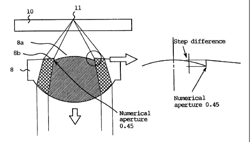
as shown in Fig. 3, a step (difference in level) is provided at a boundary
between the outer
portion and the inner portion of the object lens 8 to decrease Zernike's fifth
spherical
aberration component in the aberration components. Thus, the side lobes of the
light spot 11
are reduced and this improves the recording and reproduction performance.
Figs. 5 and 6 show graphs on a relationship between step height (or difference
in
height, converted to difference in phase of light of wavelength 650 nm) in the
object lens and
CA 02333179 2004-04-14
11
spherical aberration of converging spot and on a relationship between step
height in the
object lens and side lobes (wherein the main lobe is displayed to have
amplitude of 100 %),
respectively. It is apparent that by setting an appropriate value of the phase
step, the fifth
spherical aberration can be decreased and that the side lobes can be reduced.
In order to
suppress the fifth aberration equal to or smaller than 20 m~, (rms), it is
preferable that the
phase shift is between 50 and 150 degrees. When the phase step (phase
difference) is
changed, the total aberration is not changed much. In this embodiment, the
step is set to an
amount in correspondence to 100 degrees of phase difference.
On the other hand, when the optical disk 18 of plate thickness 1.2 mm, such as
CD, is
used for recording or reproduction the range of the object lens 8 numerical
aperture of 0.45 is
set for the optimum design plate thickness 0.9 mm, so that the aberration of
the light
transmitting it is suppressed to a similar order to the prior art structure.
As shown in Fig. 4,
the light beam transmitting the outer portion 8b of the object lens 8 has
large spherical
aberration and diffuses in a relatively wide range in the optical disk 18
information plane, and
the reflected light also is diffused with large spherical aberration.
Therefore, the
reflected light of the light transmitting the outer portion 8b does not
generally enter the
photodetector 22. Then, without providing a means for limiting numerical
aperture, CD
reproduction becomes possible at numerical aperture 0.45. -
Fig. 7 schematically shows an apparatus for recording and reproducing optical
information which uses the above-mentioned optical head 100. The structure of
the apparatus
except the optical head is similar to that of the prior art: An optical disk
102 is rotated by a
motor 104. The optical head 100 is moved along a shaft in a radial direction.
In order to
record or reproduce information in the optical head 100 a light beam emitted
by a laser diode
is focused by an object lens onto an information recording plane in the
optical disk 102. A
focus control signal for making the object lens follow the plane of the
optical disk 102 and a
tracking control signal for tracking an information track in the optical disk
102 are
detected based on output signals of the photodetector 22 in the optical head
100. A head
CA 02333179 2004-04-14
12
controller 108 performs focus control and servo control on the optical head
based on the
control signals. Further, a signal processor 110 discriminates a type of an
optical disk, and
records information to the optical disk 102 with the optical head and
reproduces optical
information recorded in information tracks in the optical disk 102 according
to the output
signals of the photodetector in the optical head 100.
It is to be noted that various optical heads which will be explained below in
following
embodiments can also be used in the apparatus for recording and reproducing
optical
information.
Next, a second embodiment of the invention is explained with reference to
relevant
drawings. Figs. 8 and 9 show an optical system of an optical head according to
the second
embodiment of the invention. Fig. 8 shows a situation for recording and
reproduction to and
from an optical disk 10 of plate thickness 0.6 mm, while Fig. 9 shows a
situation for
recording and reproduction to and from an optical disk 18 of plate thickness
1.2 mm. In
Fig. 8, a first module 31 for DVD comprises a laser diode 31 a of wavelength
650 nm which is
integrated as one body with photodetectors 31b and 31c for receiving light
reflected from the
optical disk 10. A light beam 32 of wavelength 650 nm emitted by the laser
diode 3l a in the
first module 31 passes through a cover glass 31 d to enter a wavelength filter
4. The
wavelength filter 4 transmits light of 650 nm and reflects light of wavelength
780 W n. Thus,
the light beam 32 passes through the wavelength filter 4 and is collimated by
a condenser lens
5 to become a generally collimated light beam. The collimated light beam 32
goes through a
polarizing hologram 35 and a wavelength plate 36 to enter an object lens of
numerical
aperture 0.6. The polarizing hologram 35 and the wavelength plate 36 are
integrated as one
body, that is fixed to a holder 38 with the object lens 37.
As shown in Fig. 10 the polarizing hologram 35 is fabricated by forming a
hologram
in a LiNb plate made of a birefringence material with proton exchange. It
transmits
extraordinary light and diffracts ordinary light. The light beam 32 is handled
as extraordinary
light by the polarizing hologram 35 and it transmits the polarizing hologram
35 without
CA 02333179 2004-04-14
13
diffraction. The wavelength plate 36 converts light of wavelength 650 nm from
linear
polarization to generally circular polarization and does not change
polarization for light of
wavelength 780 nm. Thus, the light beam 32 is converted to circular
polarization.
The object lens 37 is designed similarly to the object lens 8 in the first
embodiment.
A central portion 37a of numerical aperture equal to or smaller than 0.45 has
minimum
aberration for a disk plate thickness 0.9 mm while an outer portion 37b of
numerical aperture
equal to or larger than 0.45 has minimum aberration for a disk plate thickness
0.6 mm. The
light beam 32 is converged by the object lens 37 to form a light spot 39 on an
information
plane in the optical disk 10 of plate thickness 0.6 mm.
Next, the light 40 reflected by the optical disk 10 is condensed by the object
lens 37,
is converted by the wavelength plate 36 from the circular polarization to
linear polarization
having a polarization direction perpendicular to a polarization plane of the
light beam 32 and
enters the polarizing hologram 35. Because the reflected light 40 enters the
polarizing
hologram 35 as ordinary light, it is diffracted. The diffraction divides the
reflected light 40
into diffracted light 42a for detecting focus signal and diffracted light 42b
for detecting
tracking signal. The diffracted lights 42a and 42b are narrowed by the
condenser lens 5 and
are received by the photodetectors 31b and 31c, respectively. Reproduction
signals are
detected by one or both of the photodetectors 31b, 31c. Further, the
photodetector 31b
detects a focus control signal for making the object lens 37 follow the
information plane with
spot size detection technique and the photodetector 31 c detects a tracking
control signal for
tracking an information track with phase difference technique or push-pull
technique.
On the other hand, a second module 43 for CD comprises a laser diode 43a of
wavelength 780 nm, a hologram 43d for separating reflected light from an
optical disk to give
spacial change and photodetectors 43c, 43b for detecting the reflected light
all integrated as
one body. In Fig. 9, a part of a light beam 44 of wavelength 780 nm emitted by
the laser
diode 43a in the second module 43 passes through the hologram 43d and enters
the
wavelength filter 4. Because the wavelength filter 4 transmits light of 650 nm
and reflects
CA 02333179 2004-04-14
14
light of wavelength 780 nm, the light beam 44 is reflected by the wavelength
filter 33 and is
collimated by the condenser lens 5. The collimated light beam 44 passes
through the
polarizing hologram 35 and the wavelength plate 36 to enter the object lens of
numerical
aperture 0.6. The light beam 44 is handled as extraordinary light by the
polarizing
hologram 35 and it transmits the polarizing hologram 35 without diffraction.
Because the
wavelength plate 36 does not convert polarization direction of light of
wavelength 780 nm,
the polarization plane of the light beam 44 is maintained. Thus, the light
beam 44 is focused
by the object lens 37 to form a light spot 45 on an information plane in the
optical disk 18 of
plate thickness 1.2 mm.
The light 46 reflected by the optical disk 18 is condensed by the object lens
37, and
passes through the wavelength plate 36 and the polarizing hologram 35. Because
the
wavelength plate 36 does not change polarization direction for light of
wavelength 780 mm,
the reflected light 46 passes through the wavelength plate 36 as linear
polarization, similarly
to the light beam 44. Because the reflected light 46 enters the polarizing
hologram 35 as
extraordinary light, it is not diffracted. The light 46 that has passed
through the polarizing
hologram 35 is narrowed by the condenser lens 5 and is reflected by the
wavelength filter 4 to
enter the second module 43. The reflected light 46 entering the second module
43 is
diffracted by the hologram 43d to enter the photodetectors 43b and 43c, and
reproduction
signals are detected by one or both of the photodetectors. Further, the
photodetector 43b
detects a focus control signal for making the object lens 37 follow the
information plane with
spot size detection technique and the photodetector 43c detects a tracking
control signal for
tracking an information track with phase difference technique or push-pull
technique.
In the above-mentioned structure using two wavelengths 650 and 780 nm, when a
CD is reproduced with light of wavelength 780 nm, the numerical aperture of
the central
portion 37a of the object lens 37 has to be decreased to about 0.45. However,
if the
numerical aperture of optimum design plate thickness 0.9 mm becomes 0.45, the
light spot 11
for recording and reproduction of DVD generates aberration larger than 80 m~,
(rms).
CA 02333179 2001-07-24
Usually a light spot having aberration larger than 80 m~, (rms) has large so-
called side lobes,
so that recording and reproduction performance is deteriorated. Therefore, if
the light source
of 780 nm is added and only the numerical aperture of the central portion 8a
is increased in
the prior art optical head, the performance is not satisfactory. In this
embodiment, the
5 numerical aperture of the central portion 37a is increased, and similar to
the first
embodiment, as shown in Fig. 11, a step (difference in level) is provided at a
boundary
between the outer portion and the inner portion of the object lens 37 to
decrease fifth
spherical aberration component in the aberration components. Thus, the side
lobes of the
light spot 39 are reduced to improve the recording and reproduction
performance.
10 In order to suppress the fifth aberration to 20 m~, (rms) or less, it is
found that it is
desirable that the phase shift has a value between 50 and 150 degrees. It is
also found that the
total aberration is not changed much when the phase step (phase difference) is
changed. In
this embodiment, the step is provided by forming a smooth curve in order to
improve
formability of the object lens. By using a lens having a smooth shape, an
object lens made of
15 glass can be formed while ensuring stable performance against change in
ambient
temperature. On the other hand, when the optics disk 18 of plate thickness 1.2
mm, such as
CD, is used for recording or reproduction, the range of numerical aperture of
0.45 of the
object lens 37 is set for the optimum design plate thickness 0.9 mm so that
the aberration is
suppressed to a similar order to the prior art structure.
As shown in Fig. 12, the light beam transmitted through the outer portion 37b
of the
object lens 37 has large spherical aberration and diffuses in a relatively
wide range in the
information plane in an optical disk 18, and the reflected light is also
diffused with large
spherical aberration. Therefore, the reflected light of the light transmitted
through the outer
portion 37b does not generally enter the photodetectors 43b, 43c. Thus,
without providing a
means for limiting numerical aperture CD reproduction becomes possible at
numerical
number 0.45.
CA 02333179 2001-07-24
16
..
It is apparent from the above-mentioned explanation that according to the
first and
second embodiments a lens can be provided which can reproduce a CD as well as
a DVD by
increasing NA for CD reproduction and by using a laser of 780 nm. Thus,
compatibility of
DVD and CD is realized with a simple optical head including one object lens.
Further, an
S optical head and an optical disk drive can be compactly fabricated.
Next, a third embodiment of the invention is explained with reference to
relevant
drawings. An optical head of the third embodiment has a simple structure which
realizes
compatibility of DVD and CD by using one object lens having double optimum
design plate
thicknesses. The object lens has large NA for CD reproduction and can
reproduce a CD with
a laser of 780 nm while reproducing a DVD.
Figs. 13 and 14 shows an optical system of an optical head according to the
third
embodiment of the invention. Fig. 13 shows a situation for recording and
reproduction to and
from an optical disk 10 of plate thickness 0.6 mm, while Fig. 14 shows a
situation for
recording and reproduction to and from an optical disk 18 of plate thickness
1.2 mm. An
optical system uses laser diodes 1 and 15 which generate light beams of 650 nm
and of
870 nm, respectively. The optical system uses a common object lens 108 which
focuses the
light beam onto an optical disk. In detail, a section consisting of a laser
diode, a beam
splitter, a cylindrical lens and a photodetector is provided for each
wavelength, but light
beams of different wavelengths from two optical paths are guided to one
optical path by
using a wavelength filter which transmits light of wavelength 650 nm and
reflects light of
wavelength 780 nm. A further section from the wavelength filter 4 to the
object lens 108 is
used commonly. Generally, in an optical head for reproduction of optical
information media
of disk plate thickness t2 (0.6 mm) or t1 (1.2 mm), the optimum design plate
thickness at the
central portion of the object lens 108 is set to a value from t1 *0.6 to t1
and that at the
outer portion is set to 0.6 mm. The range of the optimum design plate
thickness is
determined experimentally. Further, a step is provided for a phase shift
element (optical plate
element) 107 to be cooperated with the object lens 108. Thus, information can
be recorded or
CA 02333179 2001-07-24
17
reproduced for an information medium of disk plate thickness t1 and for that
of disk plate
thickness t2 in a state where side lobes are small.
The optical head is explained further. When an optical disk 10 of plate
thickness
0.6 mm is recorded or reproduced with a light beam of wavelength 650 nm, in
Fig. 14, about
a half of a light beam 2 (for DVD) of wavelength 650 nm emitted by the first
laser diode 1
enters the wavelength filter 4 from the beam splitter. The wavelength filter 4
is designed to
transmit light of wavelength 650 nm and to reflect light of wavelength 780 nm.
Thus, the
wavelength filter 4 transmits the light beam 2, which is collimated by a
condenser lens 5 to
become a generally collimated light beam. The collimated light beam 2 is
reflected by a
mirror 6, passes through a phase shift element 107 as the optical plate
element and enters the
object lens 108 of numerical aperture 0.6.
With reference to Figs. 1 S and 16, a structure and arrangement of the phase
shift
element 107 and the object lens 108 are explained. The phase shift element 107
and the
object lens 108 are arranged so that the centers thereof coincide with the
center axis of the
light beam. The object lens 108 comprises a central portion (inner region)
108a near the
center axis of light beam and an outer portion (outer region) l O8b far from
the center axis.
The central portion 108a has a plane optimized to converge the light beam in
the inner region
onto a thin optical disk, while the outer portion 108b has a plane optimized
to converge the
light beam in the outer region onto an optical disk thicker than the thin
optical disk. Further,
the phase shift element 107 is an optical plate element having a step in order
to change the
phase. By combining the phase shift element 107 and the object lens 108, the
phase of the
light beam in an innermost portion of the outer portion 108b of the object
lens 108 is shifted
relative to the phase of the light beam in an outermost portion of the central
portion 108a.
In concrete, the object lens 108 is designed so that a central portion 108a of
numerical
aperture equal to or smaller than 0.45 has minimum aberration for a disk plate
thickness
0.9 mm while an outer portion 108b of numerical aperture equal to or larger
than 0.45 has
minimum aberration for a disk plate thickness 0.6 mm. The light beam 2 is
converged by the
CA 02333179 2001-07-24
18
object lens 108 to form a light spot 111 on an information plane in the
optical disk 10 of plate
thickness 0.6 mm.
Next, the light 112 reflected by the optical disk 10 is condensed by the
object
lens 108, passes the phase shift element 107, and the minor 6 and is condensed
by the
condenser lens 5. Then, the narrowed light beam 112 passes through the
wavelength filter 4
to enter the beam splitter 3. About half of the light incident on the beam
splitter 3 is
reflected. Then, the light beam 112 travels through a cylindrical lens 13 and
is received by a
photodetector 14. The photodetector 14 detects not only reproduction signals,
but also a
focus control signal for making the object lens 108 follow the information
plane with
astigmatism technique and a tracking control signal for tracking an
information track with
phase difference technique or push-pull technique.
On the other hand, as shown in Fig. 14, a light beam 16 (for CD) of wavelength
780 nm is emitted by the laser diode 15, about half of which passes through a
beam
splitter 17 to enter the wavelength filter 4. Because the wavelength filter 4
is designed to
reflect light of wavelength 780 nm, the light beam 16 is reflected by the
wavelength filter 4
and is collimated by the condenser lens 5. The collimated light beam 16 passes
the mirror 6
and the phase shift element 107 and enters the object lens 108 of numerical
aperture 1.2. The
light beam 2 of wavelength 780 nm is converged by the object lens 108 to form
a light
spot 119 on an information plane in the optical disk 18 of plate thickness 1.2
mm.
The light 120 reflected by the optical disk 18 is collected by the object lens
108,
passes the mirror 6 and is condensed by the condenser lens 5. The light 120 is
then reflected
by the wavelength filter 4 and enters the beam splitter 17. About half of the
light incident on
the beam splitter 17 is reflected. The light 120 then passes through a
cylindrical lens 21 and
is received by a photodetector 22. The photodetector 22 detects not only
reproduction
signals, but also the focus control signal with astigmatism technique and the
tracking control
signal with phase difference technique or push-pull technique.
CA 02333179 2001-07-24
19
The object lens 108 and the phase shift element 107 are fixed so as to keep
dynamical
balance relative to a center of gravity 123 of a moving device comprising an
object lens
holder 109 having a drive means movable in focus direction as optical axis of
the object lens
and in tracking direction as a radial direction of the disk. Because the
dynamical balance of
the object lens 108 and the phase shift element 107 is kept relative to the
center of gravity of
the movable device, even when a balancer or the like is not used, distortion
relative to the
optical axis of the object lens 108 is small. Therefore, an optical head and
an information
recording and reproducing apparatus have good quality of signals on recording
and on
reproduction.
In the above-mentioned structure using two wavelengths 650 and 780 nm, when a
CD is reproduced with light of wavelength 780 nm, the numerical aperture of
the central
portion 108a of the object lens 108 has to be decreased to about 0.45.
However, if the
numerical aperture of optimum design plate thickness 0.9 mm becomes 0.45, the
light spot 11
for recording and reproduction of DVD generates aberration larger than 80 m~,
(rms).
Usually a light spot having aberration larger than 80 m~, (rms) has large so-
called side lobes,
deteriorating recording and reproduction performance. Therefore, if the light
source of
780 nm is added and only the numerical aperture of the central portion 8a is
increased in the
prior art structure, the performance is not satisfactory. In this embodiment,
the numerical
aperture of the central portion 108a of the object lens 108 is increased, and
an optical step is
provided at a boundary between the inner portion 107a and the outer portion
107b of the
phase shift element 107. Thus, fifth spherical aberration component in the
aberration
components is decreased for the light spot formed after transmitting the
object lens 108. As
shown for example in Fig. 15, the optical step is formed by thinning the
thickness in the inner
portion 107b. By providing the step, the side lobes of the light spot 39 are
reduced for light
beams of the two wavelengths to improve the recording and reproduction
performance.
Because the phase shift element 107 and the object lens 108 are provided
separately, it is
advantageous that the shape of the object 108 can be simplified. It is also
advantageous that a
CA 02333179 2001-07-24
glass lens favorable for change in ambient temperature can be easily adopted.
In order to
suppress the fifth aberration equal to or smaller than 20 m~. (rms), it is
preferable that the
phase shift is in a range between 50 and 1 SO degrees. When the phase step is
changed, the
total aberration is not changed much. In this embodiment, the step is set to
an amount in
5 correspondence to 125 degrees of phase difference of light of wavelength 650
nm.
On the other hand, when the optical disk 18 of plate thickness 1.2 mm such as
CD is
used for recording or reproduction, the range of numerical aperture of 0.45 of
the object
lens 108 is set for the optimum design plate thickness 0.9 mm, so that the
aberration of the
light is suppressed to a similar order to the prior art structure. As shown in
Fig. 16, the light
10 beam travelling through the outer portion 108b of the object lens 108 has
large spherical
aberration and is diverged in a relatively wide range in the information plane
in an optical
disk 18, and the reflected light also is diverged with large spherical
aberration. Therefore, the
reflected light of the light travelling through the outer portion 108b does
not generally enter
the photodetector 22. Thus, without providing a means for limiting numerical
aperture, CD
15 reproduction becomes possible at numerical number 0.45.
Next, an optical head according to a fourth embodiment of the invention is
explained
with reference to relevant drawings. An optical head of the fourth embodiment
comprises
modules 31, 43 wherein a light source and a photodetector are integrated as
one body.
Further, a phase shift element 137, a wavelength plate 136 and a polarizing
hologram 135 are
20 integrated as one body. Figs. 17 and 18 show an optical system of the
optical head. Fig. 17
shows a situation for recording and reproduction to and from an optical disk
10 of plate
thickness 0.6 mm, while Fig. 18 shows a situation for recording and
reproduction to and from
an optical disk 18 of plate thickness 1.2 mm.
In Fig. 17, the first module 31 for DVD has a laser diode 31a of wavelength
650 nm
and photodetectors 31 b, 31 c for detecting light reflected from an optical
disk 10. The laser
diode 31 a and the photoconductors 31 b, 31 c are integrated as one body. A
light beam 32 of
wavelength 650 nm emitted from the laser diode 31 a transmits a cover glass 31
d to enter a
CA 02333179 2004-04-14
21
wavelength filter 4. The wavelength filter 4 is designed to transmit light of
wavelength 650
nm and to reflect light of wavelength 780 run. Thus, the light beam 32
transmits the
wavelength filter 4 and is collimated by a condenser lens 5 to become a
generally collimated
light beam. The collimated light beam 32 transmits a polarizing hologram 135,
a wavelength
plate 136 and a phase shift element 137 as an optical plate element and enters
the object lens
108 of numerical aperture 0.6.
The polarizing hologram 135, the wavelength plate 136 and the phase shift
element 137 are integrated as one body, and they are fixed with the object
lens 138 to a
holder 139 for the object lens 138. As shown in Fig. 10, the polarizing
hologram 135 is
fabricated by forming a hologram in a LiNb plate made of a birefringence
material with
proton exchange. The polarizing hologram 135 transmits extraordinary light and
diffracts
ordinary light. The light beam 32 is handled as extraordinary light by the
polarizing
hologram 135, and it transmits the polarizing hologram 135 without
diffraction. The
wavelength plate 136 converts light of wavelength 650 nm from linear
polarization to
generally circular polarization, while it does not change polarization for
light of wavelength
780 nm. Thus, the light beam 32 is converted to circular polarization.
Similarly to the object lens 108 in the third embodiment, the object lens 138
is
designed to have double optimum plate thicknesses. As shown in Figs. 19 and
20; a central
portion 138b of numerical aperture equal to or smaller than 0.45 is designed
to have
minimum aberration for a disk plate thickness 0.9 mm while an outer portion 13
8b of
numerical aperture equal to or larger than 0.45 is designed to have minimum
aberration for a
disk plate thickness 0.6 mm. The light beam 32 is converged by the object lens
138 to form a
light spot 141 on an information plane in the optical disk 10 of plate
thickness 0.6 mm.
The light 140 reflected by the optical disk 10 is condensed by the object lens
138,
passes the phase shift element 137 and is converted by the wavelength plate
136 from circular
polarization to linear polarization in polarization direction perpendicular to
polarization plane
of the light beam 32. Because the reflected light 140 enters the polarizing
hologram 135 as
CA 02333179 2004-04-14
22
ordinary light, it is diffracted. On the diffraction, the reflected light is
divided into a
diffracted light 142a for detecting focus signal and another 142b for
detecting tracking signal.
The diffracted lights 142a, 142b are narrowed by a condenser lens 5 to enter
the
photodetectors 31 b, 31 c, and reproduction signals are detected by one or
both of the
photodetectors. Further, the photodetector 31 b detects a focus control signal
for making the
object lens 37 follow the information plane with spot size detection technique
and the
photodetector 31c detects a tracking control signal for tracking an
information track with
phase difference technique or push-pull technique.
On the other hand, the second module 43 for CD has a laser diode 43a of
wavelength
780 nm, a hologram 43d for separating the reflected light to give spacial
change and
photodetectors 43b, 43c for detecting reflected light from an optical disk 10.
The laser
diode 43a, the hologram 43d and the photoconductors 43b, 43c are integrated as
one body. In
Fig. 18, a part of a light beam 44 of wavelength 780 nm emitted from the laser
diode 43a
passes through the hologram 43d to enter the wavelength filter 4. Because the
wavelength
filter 4 reflects light of wavelength 780 nm, the light beam 44 is reflected
by the wavelength
filter 4 and collimated by a condenser lens 5. The collimated light beam 44
travels through
the polarizing hologram 135, the wavelength plate 136 and the phase shift
element 137 and
enters the object lens of numerical aperture 0.6. The polarizing hologram 32
handles the light
beam 44 as extraordinary light, and the light beam 44 is transmitted without
diffraction. The
wavelength plate does not change the polarization direction for light of
wavelength 780 nm,
so that the polarization plane of the light beam 44 is maintained. The light
beam 44 is
focused by the object lens 44 and forms a light spot 149 on an information
plane in an optical
disk 18 of plate thickness 1.2 mm.
The light 146 reflected by the optical disk 18 is collected by the object lens
138 and
transmitted through the phase shift element 137, the wavelength plate 136 and
the polarizing
hologram 135. Because the wavelength plate 136 does not change polarization
direction for
light of wavelength 780 nm, the reflected light 146 travels though the
wavelength plate 136
3.
CA 02333179 2004-04-14
23
as linear polarization, similar to the light beam 44. Because the reflected
light 146 enters the
polarizing hologram 135 as extraordinary light, it is not diffracted. The
light 146 from the
polarizing hologram 135 is narrowed by the condenser lens 5 and is reflected
by the
wavelength filter 4 to enter the second module 43. The reflected light 46
entering the second
module 43 is diffracted by the hologram 43d to enter the photodetectors 43b
and 43c, and
reproduction signals are detected by one or both of the photodetectors.
Further, the
photodetector 43b detects a focus control signal for making the object lens 37
follow the
information plane with spot size detection technique and the photodetector 43
c detects a
tracking control signal for tracking an information track with phase
difference technique or
push-pull technique. Further, the object lens 138 and the phase shift element
137 are fixed so
as to keep dynamical balance relative to a center of gravity153 of a moving
device
comprising the object lens holder 139 having a drive means movable in focus
direction as
optical axis of the object lens and in tracking direction as a radial
direction of the disk.
In the above-mentioned structure using two wavelengths 650 and 780 nm, when a
CD
is reproduced with light of wavelength 780 nm, the numerical aperture of the
central portion
138a of the object lens 138 is increased similarly to the third embodiment,
and as shown in
Fig. 19, a step is provided at a boundary between the outer portion and the
inner portion of
the object lens 137. Thus, the fifth spherical aberration component in the
aberration
components of the light spot 140 formed after transmitting the object lens 138
is decreased,
and the side lobes of the light spot 149 are reduced, to improve the recording
and
reproduction performance. In order to suppress the fifth aberration equal to
or smaller
than 20 m7~ (rms), it is preferable that the phase shift is between 50 and 150
degrees. When
the phase step is changed the total aberration is not significantly changed.
In this
embodiment, the step is set to an amount in correspondence to 125 degrees of
phase
difference.
On the other hand, when the optical disk 18 of plate thickness 1.2 mm such as
CD is
used for recording or reproduction; the range of numerical aperture of 0.45 of
the object
CA 02333179 2001-07-24
24
lens 138 is set for the optimum design plate thickness 0.9 mm, so that the
aberration of the
light transmitting it is suppressed to a similar order to the prior art
structure. As shown in
Fig. 20, the light beam transmitting the outer portion 138b of the object lens
138 has large
spherical aberration and is diverged in a relatively wide range in the
information plane in an
optical disk 18, and the reflected light also is diverged with large spherical
aberration.
Therefore, the reflected light of the light transmitting the outer portion
138b does not
generally enter the photodetectors 43a, 43c. Then, without providing a means
for limiting
numerical aperture, CD reproduction becomes possible at numerical number 0.45.
As explained above, the phase shift element 137 has the optical step added to
the
optical plate element. In the third embodiment, the phase shift element 137 is
provided
separately, while in the fourth embodiment, the phase shift element 137 is
integrated with the
polarizing hologram and the phase shift element. As to the two cases, the
phase shift element
having the optical step can be fabricated, for example, by forming a step with
etching or with
molding of transparent resin. Alternatively, instead of the step, a similar
function can be
obtained by depositing an anisotropic film of a different refractive index.
Alternatively, a
step (difference in level) or a film of different refractive index is formed
on one of the planes
of the polarizing hologram. Needless to say, it may also be formed on the
wavelength plate.
The phase shift element has a simple structure that changes the phase of light
beam by
the step or the film of different refractive index, so that it is easy to
optimize the phase shift.
Therefore, optimization for each optical head in various models is easily
performed and
development period can be shortened.
In the above-mentioned third and fourth embodiments, two light sources are
used and
light beams of different wavelengths are used. However, for an optical head
using a light
beam of one wavelength, an object lens having an inner region and an outer
region and a
phase shift element having an inner region and an outer region can be used
similarly to the
above embodiments so as to improve performance of recording and reproduction
for two
types of optical information recording media.
CA 02333179 2001-07-24
Next, advantages of the third and fourth embodiments are explained. In these
embodiments, an optical head can be used for CD reproduction as well as for
DVD
reproduction, by increasing NA for CD reproduction and by using a laser of 780
nm. The
compatibility for CD and DVD can be realized with a simple optical head
including one
5 optical head. Further, an optical head and an optical information recording
and reproducing
apparatus can be compactly and simply fabricated.
Further, the means for shifting phase is realized by a simple technique to
shift the
phase of light beam by forming the step or by depositing the film of different
refractive index
so that it is easy to optimize the phase shift. Therefore, optimization for
each optical head in
10 various models is easily performed, and development period can be
shortened.
Because the dynamical balance of the object lens and the phase shift element
is kept
relative to the center of gravity of the movable device, even when a balancer
or the like is not
used distortion relative to the optical axis of the object lens 108 is small.
Therefore, an
optical head and an information recording and reproducing apparatus have good
quality of
15 signals on recording and on reproduction.
Next, a fifth embodiment of the invention is explained with reference to Figs.
21
to 24. Figs. 21 and 22 show an optical system of an optical head according to
the fifth
embodiment of the invention. Fig. 21 shows a situation for recording and
reproduction to and
from an optical disk 10 of plate thickness 0.6 mm such as DVD, while Fig. 22
shows a
20 situation for recording and reproduction to and from an optical disk 18 of
plate thickness
1.2 mm such as CD. Further, Figs. 23 and 24 show a structure around the object
lens and the
phase shift element according to the fifth embodiment of the invention.
In Fig. 21, a light beam 2 of wavelength 650 nm is emitted by a laser diode 1,
about
half of which travels through a beam splitter 3 to enter a wavelength filter
4. The wavelength
25 filter 4 is designed to transmit light of wavelength 650 nm and to reflect
light of wavelength
780 nm. Thus, the light beam 2 passes through the wavelength filter 4 and is
collimated by a
condenser lens 5 to become a generally collimated light beam. The collimated
light beam 2
CA 02333179 2001-07-24
26
is reflected by a mirror 6, passes through an optical plate element 271 and
enters an object
lens 208 of numerical aperture 0.6. The light beam 2 transmitted through the
optical plate
element 271 is converged by the object lens 208 to form a light spot 211 on an
information
plane in the optical disk 10 of plate thickness 0.6 mm. The optical plate
element 271 and the
object lens 208 are held as an integral body with a holder 209 for holding the
object lens, and
its position is controlled by a driver 23.
The light 212 reflected by the optical disk 10 is condensed by the object lens
208,
passes the optical plate element 271 and the mirror 6 and is narrowed by the
condenser lens 5.
Then, the light beam 212 travels through the wavelength filter 4 to enter the
beam splitter 3.
About half of the light incident on the beam splitter 3 is reflected. Then,
the light beam 212
passes through a cylindrical lens 13 and is received by a photodetector 14.
The photodetector
14 detects not only reproduction signals, but also a focus control signal for
making the object
lens 208 follow the information plane with astigmatism technique and a
tracking control
signal for tracking an information track with phase difference technique or
push-pull
technique.
On the other hand, in Fig. 22, a light beam 16 of wavelength 780 nm is emitted
by a
laser diode 15, about half of which travels through a beam splitter 17 to
enter the wavelength
filter 4. Because the wavelength filter 4 is designed to reflect light of
wavelength 780 nm,
the light beam 16 is reflected by the wavelength filter 4 and is collimated by
the condenser
lens 5. The collimated light beam 16 passes the minor 6, transmits the optical
plate
element 271 and enters the object lens 208 of numerical aperture 1.2. The
light beam 2 of
wavelength 780 nm is converged by the object lens 8 to form a light spot 19 on
an
information plane in the optical disk 18 of plate thickness 1.2 mm.
Next, the light 220 reflected by the optical disk 18 is collected by the
object lens 208,
passed through the optical plate element 271, reflected by the mirror 6 and
condensed by the
condenser lens 5. Then, it is reflected by the wavelength filter 4 to enter
the beam splitter 17.
About half of the light incident on the beam sputter 17 is reflected. Then,
the light beam 220
CA 02333179 2001-07-24
27
passes through a cylindrical lens 21 and is received by a photodetector 22.
The photodetector
22 detects not only reproduction signals, but also the focus control signal
with astigmatism
technique and the tracking control signal with phase difference technique or
push-pull
technique.
Here, the optical plate element 271 and the object lens 208 are explained in
detail.
The object lens 208 is designed so that aberration becomes minimum for disk
plate thickness
0.6 mm for all the portion of NA equal to or smaller than 0.6 when only the
object lens 208 is
used without association with the optical plate element 271. That is, it has a
plane optimized
to converge the light beam transmitting the object lens 208 onto an optical
disk of thin
transparent plate. Then, the object lens 208 can be used for an optical head
for recording or
reproducing to and from an optical disk of plate thickness 0.6 mm.
On the other hand, the optical plate element 271 has the inner region 271 a
near the
central axis of light beam and the outer region 271 b far from the central
axis. In an optical
head which uses two wavelengths 650 and 780 nm, when a disk of plate thickness
0.6 mm is
reproduced with light of wavelength 780 nm, NA of the inner region 271a of the
optical plate
element 271 has to be set to about 0.45. However, when NA of optimum design
plate
thickness 0.9 mm becomes 0.45, aberration exceeding 80 m~, (rms) is generated
in the light
spot 211 for recording or reproduction of a DVD. Usually a light spot having
aberration
larger than 80 m~, (rms) has large so-called side lobes, that deteriorates
recording and
reproduction performance. Therefore, if the light source of 780 nm is added
and only the
numerical aperture of the central portion is increased in the prior art
structure, the
performance is not satisfactory. In this embodiment, as shown in Fig. 23, the
numerical
aperture of the inner region 271 a of the optical plate element 271 is
increased, and a step is
provided at a boundary between the inner region 271a and the outer region 271b
of the
optical plate element 271. Then, Zernike's fifth spherical aberration
component in the
aberration components is decreased, and the side lobes of the light spot are
reduced, to
CA 02333179 2001-07-24
28
improve the recording and reproduction performance. In this embodiment, the
amplitude of
the step is set to 125 degrees of phase difference.
The optical plate element 271 is designed to have a plane which minimizes
aberration
for a transparent flat plate of disk plate thickness 0.9 mm when cooperated
with the object
S lens 271 when it is cooperated with the object lens 208. The plane of the
inner region of the
optical plate element 271 has a plane optimized to converge the light beam
transmitting the
inner region 271 a onto an optical disk of thinner transparent plate among a
plurality of optical
disks. Such a transparent plate is, for example a transparent plate having
thickness equal to
or larger than t1 *0.7 wherein t1 denotes the thickness of transparent plate
having the largest
thickness in a plurality of types of optical disks (1.2 mm in this example).
On the other hand,
the outer region 271 b of NA equal to or larger than 0.45 has a flat plane,
and it only gives
phase shift determined by a product of the thickness of the outer region 271b
and the
refractive index of the optical plate element 271. Further, the phase of the
outer region is set
so that the phase of the beam in the innermost portion of the outer region is
set to be shifted
relative to the phase of the beam in the outermost portion of the inner
region. The optical
plate element 271 is made of glass and the shape of its surface is obtained by
etching the
surface of a flat glass sheet.
A relationship between the above-mentioned step (converted to the phase of the
light
of wavelength 650 nm) and the aberrations is similar to that shown in Fig. 5
on the first
embodiment, and values of the step and the side lobes are similar generally to
those in the
graph shown in Fig. 6. By setting the phase step to an appropriate value, the
fifth spherical
aberration is decreased, and side lobes can be reduced. In order to suppress
the fifth
aberration below 20 m~, (rms), it is also found that it is necessary to set
the phase shift
between 50 and 150 degrees. When the amplitude of the phase step is changed,
total
aberration is not affected much.
On the other hand, when an optical disk 18 of plate thickness 1.2 mm such as
CD is
used for recording or reproduction, the aberration of the light beam
transmitting the range of
CA 02333179 2004-04-14
29
NA 0.45 of the optical plate element 271 is suppressed to a similar degree to
that of prior art
by setting the range to optimum design plate thickness 0.9 mm. ~As shown in
Fig. 24, because
the light beam in the outer region 271a of the optical plate element 271
passes through the
object lens 208 wholly, it has large aberration and is dispersed in a
relatively wide range on
the information plane in the optical disk 271. Further, the reflected light in
the outer
region 271b is also dispersed with large spherical aberration. Then, the
reflected light in the
outer region 271b does not substantially enter the photodetector 22, and a
disk of plate
thickness 1.2 mm can be reproduced with NA 0.45 without providing a means for
limiting the
aperture.
Next, a sixth embodiment of the invention is explained With reference to Figs.
25
to 28. Figs. 25 and 26 show an optical system of an optical head according to
the sixth
embodiment of the invention. Fig. 25 shows a situation for recording and
reproduction to and
from an optical disk of plate thickness 0.6 mm such as DVD, while Fig. 26
shows a situation
for recording and reproduction to and from an optical disk of plate thickness
1.2 mm such as
CD. Further, Figs. 27 and 28 show details around the object lens and the phase
shift element.
Recording and reproduction to and from an optical disk I 8 of plate thickness
1.2 mm
such as CD are explained. In Fig. 27, a first module 31 for DVD comprises a
laser diode 31a
of wavelength 650 nm integrated as one body with photodetectors 31 b and 31 c
for receiving
light reflected from the optical disk 10. A light beam 32 of wavelength 650 nm
emitted by
the laser diode 31 a in the first module 31 passes through a cover glass 31 d
to enter a
wavelength filter 4. The wavelength filter 4 transmits light of 650 nm and
reflects light of
wavelength 780 nm. Thus, the light beam 32 passes through the wavelength
filter 4 and is
collimated by a condenser lens 5 to become a generally collimated light beam.
The
collimated light beam 32 passes through a polarizing hologram 235 and a
wavelength
plate 235 to enter an object lens 208 of numerical aperture 0.6.
The polarizing hologram 235 and the wavelength plate 236 are integrated as one
body, and they are fixed to a holder 209 with the object lens 208. As shown in
Fig. 10, the
CA 02333179 2004-04-14
polarizing hologram 235 is fabricated by forming a hologram in a LiNb plate
made of a
birefringence material with proton exchange. It transmits extraordinary light
and diffracts
ordinary light. The light beam 32 is handled as extraordinary light by the
polarizing
hologram 235 and is transmitted by the polarizing hologram 235 without
diffraction. The
5 wavelength plate 236 converts light of wavelength 650 nm from linear
polarization to
generally circular polarization, but it does not change polarization for light
of wavelength
780 nm. Thus, the light beam 32 is converted to circular polarization by the
wavelength
plate 236. The light beam of circular polarization transmitted by the optical
plate element
271 is converged by the object lens 208 to form a light spot 241 on an
information plate in an
10 optical disk 10 of plate thickness 0.6 mm.
The object lens 208 and the optical plate element 271 are designed similarly
to the
counterparts in the fifth embodiment. The object lens 208 is designed so that
aberration
becomes minimum for the portion of NA equal to or smaller than 0.45 for an
optical disk of
plate thickness 0.6 mm when it is not used in cooperation with the optical
plate element 271.
15 On the other hand, the optical plate element 271 comprises an inner region
271a near the
optical axis and an outer region 271b far therefrom. The numerical aperture of
the inner
region 271 a is increased, while a step is provided between the inner and
outer regions 271 a,
271 b. The amplitude of the step is set to 125 as phase step.
Next, the light 240 reflected by the optical disk 10 is condensed by the
object
20 lens 208, passed through the optical plate element 271, converted by the
wavelength
plate 236 from the circular polarization to linear polarization having a
polarization direction
perpendicular to a polarization plane of the light beam 32 and enters the
polarizing
hologram 235. Because the reflected light 240 enters the polarizing hologram
235 as
ordinary light, it is diffracted. The diffraction divides the reflected light
240 into diffracted
25 light 242a for detecting focus signal and diffracted light 242b for
detecting tracking signal.
The diffracted lights 242a and 242b are narrowed by the condenser lens 5 to be
received by
the photodetectors 31b and 31c, respectively, and reproduction signals are
detected by one or
CA 02333179 2004-04-14
31
both of the photodetectors. Further, the photodetector 31 b detects a focus
control signal for
making the object lens 208 follow the information plane with spot size
detection technique
and the photodetector 31 c detects a tracking control signal for tracking an
information track
with phase difference technique or push-pull technique.
On the other hand, a second module 43 for CD comprises a laser diode 43a of
wavelength 780 nm, a hologram 43d for separating reflected light from an
optical disk to give
spacial change and photodetectors 43a, 43b which detects the reflected light,
and they are
integrated as one body. In Fig. 25, a part of a light beam 44 of wavelength
780 nm emitted
by the laser diode 43a passes through the hologram 43d and enters the
wavelength filter 4.
Because the wavelength filter 4 transmits light of 650 nm and reflects light
of wavelength
780 nm, the light beam 44 is reflected by the wavelength filter 4 and is
collimated by the
condenser lens 5. The collimated light beam 44 travels through the polarizing
hologram 235
and the wavelength plate 236 to enter the object lens of numerical aperture
0.6. The light
beam 44 is handled as extraordinary light by the polarizing hologram 235 and
it is transmitted
through the polarizing hologram 235 without diffraction. Because the
wavelength plate 236
does not convert polarization direction of light of wavelength 780 nm, the
polarization plane
of the light beam 44 is maintained. Thus, the light beam 44 is focused by the
object lens 208
to form a light spot 249 on an information plane in the optical disk 18 of
plate thickness
1.2 mm.
Next, the light 246 reflected by the optical disk 18 is condensed by the
object lens 208
and transmits the wavelength plate 236 and the polarizing hologram 235.
Because the
wavelength plate 236 does not change polarization direction for light of
wavelength 780 mm,
the reflected light 246 transmits the wavelength plate 236 as linear
polarization, similarly to
the light beam 44. Because the reflected light 246 enters the polarizing
hologram 235 as
extraordinary light, it is not diffracted. The light 246 transmitted through
the polarizing
hologram 235 is narrowed by the condenser lens 5 and is reflected by the
wavelength
filter 4 to enter the second module 43. The reflected light 246 entering the
second
CA 02333179 2001-07-24
32
module 43 is diffracted by the hologram 43d to enter the photodetectors 43b
and 43c, and
reproduction signals are detected by one or both of the photodetectors.
Further, the
photodetector 43b detects a focus control signal for making the object lens
208 follow the
information plane with spot size detection technique and the photodetector 43c
detects a
tracking control signal for tracking an information track with phase
difference technique or
push-pull technique.
By setting the phase step to an appropriate value, the fifth spherical
aberration is
decreased, and side lobes can also be reduced, similarly to the fifth
embodiment as explained
above with reference to Figs. 5 and 6. In order to suppress the fifth
aberration below
20 m~, (rms), it is also found that it is necessary to set the phase shift
between 50 and 150
degrees. When the amount of the phase step is changed, total aberration is not
affected much.
On the other hand, when an optical disk 18 of plate thickness 1.2 mm such as
CD is
used for recording or reproduction, the aberration of the light beam in the
range of NA 0.45
of the optical plate element 271 is suppressed to a similar degree to that of
prior art by setting
the range to optimum design plate thickness 0.9 mm. As shown in Fig. 28,
because the light
beam in the outer region 271a of the optical plate element 271 transmits the
object lens 208
wholly, it has large aberration and is dispersed in a relatively wide range on
the information
plane in the optical disk 271. Further, the reflected light in the outer
region 271b is also
dispersed with large spherical aberration. Then, the reflected light in the
outer region 271b
does not substantially enter the photodetector 22, and a disk of plate
thickness 1.2 mm can be
reproduced with NA 0.45 without providing a means for limiting the aperture.
In the fifth and sixth embodiments, the optical plate element 271 is
fabricated by
etching a glass plate but it may also be fabricated by forming glass with a
press. Because the
lens effect of the optical plate element 271 is weak, a resin of low
refractive index may be
used; therefore, injection molding or press forming for resin may also be
adopted similarly.
According to the fifth and sixth embodiments, a necessary function can be
added to an
object lens by providing the optical plate element in the optical path.
Further, this is a means
CA 02333179 2001-07-24
- 33
for realizing a form that is difficult to be added as an object lens, and an
optical head or an
optical disk drive having a desired condensing performance can be easily
provided.
Further, because the optical plate element has a simple structure fabricated
by etching
on a generally plate-like surface, its shape can easily be optimized.
Therefore, optimization
or the like for each model of optical head can easily be performed by using a
common object
lens, and a period for development can be shortened to a large extent. The
optical plate
element is also appropriate for production in small lots.
Further, because the optical plate element and the object lens are separate
parts, the
shape of the object lens can be simplified. A glass lens advantageous for
change in ambient
temperature can be easily adopted.
By adopting the above-mentioned structure, the reproduction performance for an
information recording medium of small thickness such as DVD can be kept, while
numerical
aperture for an information recording medium of large thickness such as DVD
can be
increased.
Further, because the numerical aperture for an information recording medium of
large
thickness can be increased, the information recording medium of large
thickness can be
reproduced with a light source of longer wavelength. For example, reproduction
becomes
possible even for an information recording medium such as CD-R which cannot
reproduce
information due to low reflectance with use of a light source for a wavelength
for
reproduction of an information recording medium of smaller thickness.
In the above-mentioned first to sixth embodiments, the range of optimum design
plate
thickness 0.9 mm is set to NA 0.45 as an example for compatibility between DVD
and CD.
Further, it is possible to extend the range further to about 0.50 for the
compatibility between
DVD and laser disk (LD).
Next, a seventh embodiment of the invention is explained with reference to
relevant
drawings. Figs. 29 and 30 show an optical system of an optical head according
to the seventh
embodiment. Fig. 29 shows a situation for recording and reproduction to and
from an optical
CA 02333179 2001-07-24
34
disk 10 of plate thickness 0.6 mm, while Fig. 30 shows a situation for
recording and
reproduction to and from an optical disk 18 of plate thickness 1.2 mm.
In Fig. 29, a light beam 2 of wavelength 650 nm is emitted by a laser diode 1,
about
half of which passes through a beam splitter 3 to enter a wavelength filter 4.
The wavelength
S filter 4 is designed to transmit light of wavelength 650 nm and to reflect
light of wavelength
780 nm. Then, the light beam 2 passes through the wavelength filter 4 and is
collimated by a
condenser lens S to become a generally collimated light beam. The collimated
light beam 2
is reflected by a mirror 6 and enters an object lens 308 of numerical aperture
0.6. The object
lens 308 comprises a central portion 308a and an outer portion 308b. The
central portion
308a is designed so that a central portion 308a of numerical aperture equal to
or smaller
than 0.45 has minimum aberration for a disk plate thickness 0.9 mm while an
outer
portion 308b of numerical aperture equal to or larger than 0.45 has minimum
aberration for a
disk plate thickness 0.6 mm. The light beam 2 is converged by the object lens
308 to form a
light spot 311 on an information plane in the optical disk 10 of plate
thickness 0.6 mm.
Next, the light 312 reflected by the optical disk 10 is condensed by the
object
lens 308, passes a mirror 6 and is narrowed by a condenser lens 5. The
narrowed reflected
light 312 travels through a wavelength filter 4 to enter a beam splitter 17.
About half of the
light incident on the beam splitter 17 is reflected. Then, the reflected light
travels through a
cylindrical lens 13 and is received by a photodetector 14. The photodetector
14 detects not
only reproduction signals, but also a focus control signal for making the
object lens 308
follow the information plane with astigmatism technique and a tracking control
signal for
tracking an information track with phase difference technique or push-pull
technique.
On the other hand, in Fig. 30, a light beam 16 of wavelength 780 nm is emitted
by a
laser diode 15, about half of which travels through a beam splitter 17 to
enter the wavelength
filter 4. The wavelength filter 4 is designed to reflect light of wavelength
780 nm. Then, the
light beam 16 is reflected by the wavelength filter 4 and is collimated by the
condenser
lens 5. The collimated light beam 16 passes the mirror 6 and enters the object
lens 308. The
CA 02333179 2001-07-24
light beam 16 of wavelength 780 nm is converged by the object lens 308 to form
a light
spot 319 on an information plane in the optical disk 18 of plate thickness 1.2
mm.
Next, the light 320 reflected by the optical disk 18 is collected by the
object lens 308,
passes the mirror 6 and is condensed by the condenser lens 5. Then, it is
reflected by the
5 wavelength filter 4 to enter the beam splitter 17. About half of the light
incident on the beam
splitter 17 is reflected. Then, the light 320 travels through a cylindrical
lens 21 and is
received by a photodetector 22. The photodetector 22 detects not only
reproduction signals,
but also the focus control signal with astigmatism technique and the tracking
control signal
with phase difference technique or push-pull technique.
10 In the above-mentioned structure using two wavelengths 650 and 780 nm, when
a CD
is reproduced with light of wavelength 780 nm, the numerical aperture of the
central portion
308a of the object lens 308 has to be decreased to about 0.45. However, if the
numerical
aperture of optimum design plate thickness 0.9 mm becomes 0.45, the light spot
11 for
recording and reproduction of DVD generates aberration larger than 80 m~,
(rms). Usually a
15 light spot having aberration larger than 80 m~, (rms) has large so-called
side lobes, so that
recording and reproduction performance deteriorates. Therefore, if the light
source of
780 nm is added and only the numerical aperture of the central portion 308a is
increased in
the prior art structure, the performance is not satisfactory. Then, in this
embodiment, as
shown in Fig. 30, a step is provided at a boundary between the outer and inner
portions of the
20 object lens 308 to decrease Zernike's fifth spherical aberration component
in the aberration
components. Thus, the side lobes of the light spot 311 are reduced to improve
the recording
and reproduction performance.
The relationship between step (converted to phase of light of wavelength 650
nm) in
the object lens and spherical aberration of converging spot and the
relationship between step
25 height in the object lens and side lobe (wherein the main lobe is displayed
to have amplitude
of 100 %) are similar to the graphs shown in Figs. 5 and 6 in the first
embodiment. It is
apparent that by setting an appropriate value of the phase step, the fifth
spherical aberration
CA 02333179 2001-07-24
36
can be decreased and the side lobes can be reduced. In order to suppress the
fifth aberration
equal to or smaller than 20 m~, (rms), it is preferable that shift of the
phase is in a range
between 50 and 1 SO degrees. When the phase is changed, the total aberration
is not changed
much. In this embodiment, amplitude of the step is set to an amount in
correspondence to
100 degrees of phase difference.
On the other hand, when the optical disk 18 of plate thickness 1.2 mm, such as
CD, is
used for recording or reproduction, the range of numerical aperture of 0.45 of
the object
lens 308 is set for the optimum design plate thickness 0.9 mm, so that the
aberration of the
light transmitting it is suppressed to a similar order to the prior art
structure. However, it is
preferable for suppression of aberration that optical length L2 from the laser
diode 15 to the
condenser lens 5 is set to a value between 80 and 95 % of optical length L1
from the laser
diode 1 to the condenser lens 5. Further, as shown in Fig. 32, the light beam
transmitting the
outer portion 308b of the object lens 308 has large spherical aberration and
diverges in a
relatively wide range in the information plane in an optical disk 18, and the
reflected light
also is diverged with large spherical aberration. Therefore, the reflected
light in the outer
portion 308b does not generally enter the photodetector 22. Then, without
providing a means
for limiting numerical aperture, CD reproduction becomes possible at numerical
number
0.45. If the optical length L2 is set to a value equal to or smaller than 80 %
of L1, the degree
of diffusion is decreased and is not desirable for reproduction performance of
CD.
Next, an eighth embodiment of the invention is explained with reference to
relevant
drawings. Figs. 33 and 34 show an optical system in the optical system of an
optical head
according to the invention. Fig. 33 shows a situation for recording and
reproduction to and
from an optical disk 10 of plate thickness 0.6 mm, while Fig. 34 shows a
situation for
recording and reproduction to and from an optical disk 18 of plate thickness
1.2 mm.
In Fig. 33, a first module 31 for DVD comprises a laser diode 31 a of
wavelength
650 nm integrated as one body with photodetectors 31b and 31c for receiving
light reflected
from the optical disk 10. In the first module 31, a light beam 32 of
wavelength 650 nm
CA 02333179 2004-04-14
37
emitted by the laser diode 31 a passes through a cover glass 31 d to enter a
wavelength
filter 4. The wavelength filter 4 transmits light of 650 nm and reflects light
of wavelength
780 nm. Then, the light beam 32 travels through the wavelength filter 4 and is
collimated by
a condenser lens 5 to become a generally collimated light beam. The collimated
light beam
32 is transmitted through a polarizing hologram 335 and a wavelength filter 4
to enter an
object lens of numerical aperture 0.6. The polarizing hologram 335 and the
wavelength plate
336 are integrated as one body, and they are fixed to a holder 38 with the
object
lens 337. As shown in Fig. 10, the polarizing hologram 335 is fabricated by
forming a
hologram in a LiNb plate made of a birefringence material with proton
exchange. It transmits
extraordinary light and diffracts ordinary light. The light beam 32 is handled
as extraordinary
light by the polarizing hologram 335 and it transmits the polarizing hologram
335 without
diffraction. The wavelength plate 336 converts light of wavelength 650 nm from
linear
polarization to generally circular polarization and does not change
polarization for light of
wavelength 780 nm. Thus, the light beam 32 is converted to circular
polarization. The object
lens 337 is designed similarly to the counterpart 308 in the seventh
embodiment. As shown
in Figs. 35 and 36, the central portion 337a with numerical aperture in a
range of plate
thickness 0.9 mm is designed to have minimum aberration for disk plate
thickness 0.9 mm.
The light beam 32 is converged by the object lens 337 to form a light spot 339
on an
information plane in the optical disk 10 of plate thickness 0.6 mm.
Next, the light 340 reflected by the optical disk 10 is condensed by the
object
lens 337, is converted by the wavelength plate 336 from the circular
polarization to linear
polarization having a polarization direction perpendicular to a polarization
plane of the light
beam 32 and enters the polarizing hologram 335. Because the reflected light
340 enters the
polarizing hologram 335 as ordinary light it is diffracted. The diffraction
divides the
reflected light 340 into diffracted light 342a for detecting focus signal and
diffracted
light 342b for detecting tracking signal. The diffracted lights 342a and 342b
are narrowed by
the condenser lens 334 to be received by the photodetectors 31b and 31c,
respectively, and
CA 02333179 2004-04-14
38
reproduction signals are detected by one or both of the photodetectors.
Further, the
photodetector 31b detects a focus control signal for making the object lens
337 follow the
information plane with spot size detection technique and the photodetector 31
c detects a
tracking control signal for tracking an information track with phase
difference technique or
push-pull technique.
On the other hand, a second module 43 for CD comprises a laser diode 43a of
wavelength 780 ntn, a hologram 43d for separating reflected light from an
optical disk to give
spacial change and photodetectors 43a, 43b for detecting the reflected light,
all of which are
integrated as one body. In Fig. 34, a part of a light beam 44 of wavelength
780 nm emitted
by the laser diode 43a transmits the hologram 43d and enters the wavelength
filter 4.
Because the wavelength filter 4 is designed to reflect light of wavelength 780
nm, the light
beam 44 is reflected by the wavelength filter 4 and is collimated by the
condenser lens 5.
The collimated light beam 44 travels through the polarizing hologram 335 and
the
wavelength plate 336 to enter the object lens of numerical aperture 0.6. The
light beam 44 is
handled as extraordinary light by the polarizing hologram 335, and is
transmitted through the
polarizing hologram 335 without diffraction. The reflected light 346 passes
through the
polarizing hologram 335 and is narrowed by the condenser lens 5 and reflected
by the
wavelength filter 4 to enter the second module 43. The reflected light 46
entering the second
module 43 is diffracted by the hologram 43d to enter the photodetectors 43b
and 43c, and
reproduction signals axe detected by one or both of the photodetectors.
Further, the
photodetector 43b detects a focus control signal for making the object lens
337 follow the
information plane with spot size detection technique, and the photodetector
43c detects a
tracking control signal for tracking an information track with phase
difference technique or
push-pull technique.
In the above-mentioned structure using two wavelengths 650 and 780 nm, when a
CD
is reproduced with light of wavelength 780 nm, the numerical aperture of the
central portion
337a of the object lens 337 has to be decreased to about 0.45. However, if the
numerical
CA 02333179 2004-04-14
39
aperture of optimum design plate thickness 0.9 mm becomes 0.45, the light spot
for recording
and reproduction of DVD generates aberration larger than 8o m7~, (rms).
Usually a light spot
having aberration larger than 80 ma, (rms) has large so-called side lobes, so
that recording and
reproduction performance is deteriorated. Therefore, if the light source of
780 nm is added
and only the numerical aperture of the central portion 308a is increased in
the prior art
structure, the performance is not satisfactory. In this embodiment, the
numerical aperture of
the central portion 308a is increased, and similarly to the seventh
embodiment, as shown in
Fig. 35, a step is provided at a boundary between the outer portion and the
inner portion of
the object lens 337 to decrease fifth spherical aberration component in the
aberration
components. Thus, the side lobes of the light spot 339 are reduced to improve
the recording
and reproduction performance. In order to suppress the fifth aberration to 20
ma, (rms) or
less, it is found that it is desirable that the phase shift has a value
between 50 and 150
degrees. It is also found that the total aberration is not changed much when
the phase step is
changed. In this embodiment, the step is formed with a smooth curve in order
to improve
formability of the object lens. By using such a lens having a smooth shape, an
object lens
made of glass can be formed while stable performance is ensured against change
in ambient
temperature. The amplitude of the step is set to a value to be converted to
100 degrees of
phase difference.
On the other hand, when the optical disk 18 of plate thickness 1.2 mm such as
CD is
used for recording or reproduction, the range of numerical aperture of 0.45 of
the object
lens 337 is set for the optimum design plate thickness 0.9 mm, so that the
aberration of the
light transmitting it is suppressed to a similar order to the prior art
structure. However, it is
preferable for suppression of aberration that optical length L2 from the laser
diode 43a to the
condenser lens 5 is set to a value between 80 and 95 % of optical length L1
from the laser
diode 31a to the condenser lens 34. Fig. 37 shows change in focus offset
plotted against L2.
In this case, it is found that the focus offset can be set to zero by setting
L2 to 90 % of L1.
Further, the light beam transmitting the outer portion 337b of the object lens
337 has large
CA 02333179 2001-07-24
- 40
spherical aberration and diverges in a relatively wide range in the
information plane in an
optical disk 18, and the reflected light also is diverged with large spherical
aberration.
Therefore, the reflected light of the light transmitting the outer portion
337b does not
generally enter the photodetectors 43b, 43c. Then, without providing a means
for limiting
numerical aperture, CD reproduction becomes possible at numerical number 0.45.
If the
optical length L2 is set to a value equal to or smaller than 80 % of optical
length L1, the
degree of diffusion is decreased, and it is not desirable for reproduction
performance of CD.
In the seventh and eighth embodiments, a similar advantage is realized by
using a lens
fabricated by integrating a condenser lens and an object lens as one body.
It is apparent from the above-mentioned explanation that according to the
seventh and
eighth embodiments a lens can be provided which can reproduce a CD as well as
a DVD by
increasing NA for CD reproduction and by using a laser of 780 nm. Thus,
compatibility of
DVD and CD is realized with a simple optical head using one lens. Further, an
optical head
can be fabricated compactly and an optical disk drive can also be manufactured
compactly.
Further, by shortening the optical length from the laser for CD to the
condenser lens
than that from the laser for DVD to the condenser lens, aberration is
suppressed to improve
the quality of reproduction signals, and focus offset is decreased.
In the above-mentioned first to eighth embodiments, the range of optimum
design
plate thickness 0.9 mm is set to NA 0.45 as an example for compatibility
between DVD and
CD. However, it is possible to set the optimum design plate thickness to a
value equal to or
larger than 1.0 mm. Further, it is also possible to extend the range further
to about 0.50 for
the compatibility between DVD and laser disk (LD).
Next, a ninth embodiment of the invention is explained with reference to
relevant
drawings. Fig. 38 shows a situation for recording and reproduction to and from
an optical
disk 10 of plate thickness 0.6 mm, while Fig. 39 shows a situation for
recording and
reproduction to and from an optical disk 18 of plate thickness 1.2 mm. In Fig.
38, a light
beam 2 of wavelength 650 nm is emitted by a laser diode 1, about half of which
is
CA 02333179 2001-07-24
41
transmitted through a beam splitter 3 to enter a wavelength filter 4. The
wavelength filter 4 is
designed to transmit light of wavelength 650 nm and to reflect light of
wavelength 780 nm.
Then, the light beam 2 passes through the wavelength filter 4 and is
collimated by a
condenser lens 5 to become a generally collimated light beam. The collimated
light beam 2
is reflected by a minor 6, travels though a light-shielding filter 407 and
enters an object
lens 408 of numerical aperture 0.6. The light-shielding filter 407 and the
object lens 408 are
fixed to a holder 409. As shown in Fig. 40, the light-shielding filter 407
comprises a ring-like
light-shielding portion 407a and a transmitting portion 407b. As shown in Fig.
41, the light-
shielding portion 407a shields light of wavelength 650 nm and transmits light
of wavelength
780 nm, while as shown in Fig. 42, the transmitting portion 407b has
wavelength
characteristic that light is transmitted for both wavelengths of 650 and 780
nm. Further, as
shown in Fig. 43 the light-shielding portion 407a shields a part of the light
beam in
correspondence to numerical aperture from 0.37 to 0.45.
The object lens 408 is designed so that a central portion 408a of numerical
aperture
equal to or smaller than 0.45 has minimum aberration for a disk plate
thickness 0.9 mm while
an outer portion 408b of numerical aperture equal to or larger than 0.45 has
minimum
aberration for a disk plate thickness 0.6 mm. The light beam 2 shielded by the
light-shielding
filter 7 as a ring form is converged by the object lens 408 to form a light
spot 411 on an
information plane in the optical disk 10 of plate thickness 0.6 mm.
The light 412 reflected by the optical disk 10 is condensed by the object lens
408,
passes the light-shielding filter 407 and the mirror 6 and is narrowed by the
condenser lens 5.
Then, the narrowed light beam 412 passes through the wavelength filter 4 to
enter the beam
splitter 3. About half of the light incident on the beam splitter 3 is
reflected. Then, the light
412 travels through a cylindrical lens 13 and is received by a photodetector
14. The
photodetector 14 detects not only reproduction signals, but also a focus
control signal for
making the object lens 8 follow the information plane with astigmatism
technique and a
CA 02333179 2001-07-24
42
tracking control signal for tracking an information track with phase
difference technique or
push-pull technique.
On the other hand, in Fig. 39, a light beam 16 of wavelength 780 nm is emitted
by a
laser diode 15, about half of which travels through a beam splitter 17 to
enter the wavelength
filter 4. Because the wavelength filter 4 is designed to reflect light of
wavelength 780 nm,
the light beam 16 is reflected by the wavelength filter 4 and is collimated by
the condenser
lens 5. The collimated light beam 16 passes the mirror 6 and the light-
shielding filter 467 to
enter the object lens 408 of numerical aperture 1.2. As shown in the
wavelength
characteristics in Figs. 41 and 42, the light beam 16 of wavelength 780 nm
transmits both of
the light-shielding portion 407a and the transmitting portion 407b and is
converged by the
object lens 408 to form a light spot 419 on an information plane in the
optical disk 18 of plate
thickness 1.2 mm.
The light 420 reflected by the optical disk 18 is collected by the object lens
408,
passes the mirror 6 and the light-shielding filter 407 and is narrowed by the
condenser lens 5.
Then, the light 420 is reflected by the wavelength filter 4 to enter the beam
splitter 17. About
half of the light incident on the beam splitter 17 is reflected. Then, the
light passes a
cylindrical lens 21 and is received by a photodetector 22. The photodetector
22 detects not
only reproduction signals, but also the focus control signal with astigmatism
technique and
the tracking control signal with phase difference technique or push-pull
technique.
In the above-mentioned structure using two wavelengths 650 and 780 nm, when a
CD
is reproduced with light of wavelength 780 nm, the numerical aperture of the
central portion
408a of the object lens 408 has to be decreased to about 0.45. However, if the
numerical
aperture of optimum design plate thickness 0.9 mm becomes 0.45, the light spot
411 for
recording and reproduction of DVD generates aberration larger than 80 m~,
(rms). Then,
recording and reproduction performance deteriorates and if the light source of
780 nm is
added and only the numerical aperture of the central portion 408a is increased
in the prior art
structure, the performance is not satisfactory. In this embodiment, the
numerical aperture of
CA 02333179 2001-07-24
43
the central portion 408a is increased, and as shown in Fig. 43, the light-
shielding portion 407a
of the light-shielding filter 407 shields a part of the light beam 2 in
correspondence to
numerical aperture from 0.37 to 0.45, thus, aberration is decreased. That is,
the light spot 411
used for recording or reproduction of DVD is formed by synthesizing a light
beam
transmitting the central portion 408a of the object lens 408 of numerical
aperture equal to or
smaller than 0.37 and another light beam transmitting the outer portion 408b
of numerical
aperture from 0.45 to 0.6. Aberration is small in a region near the center of
optical axis of the
object lens 408 even when the design plate thickness is deviated, and for
numerical aperture
of about 0.37 the aberration is about 30 m~, (rms) when the light transmitting
the central
portion of plate thickness 0.9 mm is focused on an optical disk of plate
thickness of 0.6 mm.
Then, the recording and reproducing performance is not deteriorated.
Therefore, recording
and reproduction can be possible for a DVD by using the above-mentioned light
spot 411
synthesized from light beams transmitting the outer portion 408b and the
central portion 408a
of numerical aperture equal to or smaller than 0.37.
1 S When an optical disk of thickness 1.2 mm such as CD is subjected to
recording or
reproduction, the range of numerical number 0.45 of the object lens 408 is
designed for
optimum design plate thickness 0.9 mm, so that aberration of the light
transmitting the object
lens can be suppressed to a value about the same as that in a prior art
device. As shown in
Fig. 44, the light beam transmitting the outer portion 408b of the object lens
408 has large
spherical aberration and it is diverged in a relatively wide range on an
information plane in an
optical disk 18, and the reflected light thereof is also diverged. Therefore,
the reflected light
transmitting the outer portion 408b does not generally enter the photodetector
22. Because
the light-shielding filter 407 does not shield the light beam 16, the
numerical aperture of the
object lens becomes 0.45 for recording or reproduction of CD, and the
numerical number of
the same order as in a conventional CD drive can be obtained.
In this embodiment, the light-shielding filter 407 is a filter using an
optical thin film.
Further, a similar advantage can be obtained by providing a hologram having a
function of
CA 02333179 2004-04-14
44
wavelength selection for diffracting the light of wavelength 650 nm only for
the light-
shielding region 407a. In the above-mentioned example, a region of numerical
aperture 0.45
of the object lens 408 is provided for optimum design plate thickness 0.9 mm.
This region is
a practical region because aberration on CD reproduction is suppressed to 40
m~, (rms) for
70 % or more of the plate thickness of optical disk 18. In the above-mentioned
example, the
light-shielding portion 407a corresponds to numerical aperture from 0.45 to
0.37 of the object
lens 408. The performance for DVD can be secured for 70 % or more of the
numerical
aperture 0.45 for CD.
Next, a tenth embodiment of the invention is explained with reference to
relevant
drawings. Fig. 45 shows a situation for recording and reproduction to and from
an optical
disk 10 of plate thickness 0.6 mm, while Fig. 46 shows a situation for
recording and
reproduction to and from an optical disk 18 of plate thickness 1.2 mm. In Fig.
45, a first
module 31 for DVD comprises a laser diode 31 a of wavelength 650 nm which is
integrated as
one body with photodetectors 31b and 31c for receiving light reflected from
the optical
disk 10. In the first module 31 a, light beam 32 of wavelength 650 nm emitted
by the laser
diode 31 a passes through a cover glass 31 d to enter a wavelength filter 4.
The wavelength
filter 4 transmits light of 650 nm and reflects light of wavelength 780 nm.
Then, the light
beam 32 travels through the wavelength filter 4 and is collimated by a
condenser tens 5 to
become a generally collimated light beam. The collimated light beam 32 passes
through a
polarizing hologram 35 and a wavelength plate 436 to enter an object lens 437
of numerical
aperture 0.6. The polarizing hologram 35 and the wavelength plate 436 are
integrated as one
body, which is fixed to a holder 438 with the object lens 437. As shown in
Fig. 10, the
polarizing hologram 435 is fabricated by forming a hologram in a LiNb plate
made of a
birefringence material with proton exchange. The polarizing hologram 435
transmits
extraordinary light and diffracts ordinary light. The light beam 32 is handled
as extraordinary
light by the polarizing hologram 35, and is transmitted by the polarizing
hologram 35 without
diffraction. The wavelength plate 436 converts light of wavelength 650 nm from
linear
CA 02333179 2001-07-24
polarization to generally circular polarization but it does not change
polarization for light of
wavelength 780 nm. Thus, the light beam 32 is converted to circular
polarization. The object
lens 437 is designed similarly to the counterpart 408 in the ninth embodiment.
As shown in
Fig. 47, a central portion 437a of numerical aperture equal to or smaller than
0.45 has
5 minimum aberration for a disk plate thickness 0.9 mm while an outer portion
437b of
numerical aperture equal to or larger than 0.45 has minimum aberration for a
disk plate
thickness 0.6 mm. The light beam 32 is converged by the object lens 437 to
form a light
spot 439 on an information plane in the optical disk 10 of plate thickness 0.6
mm.
Next, the light 440 reflected by the optical disk 10 is condensed by the
object
10 lens 437, is converted by the wavelength plate 436 from the circular
polarization to linear
polarization having a polarization direction perpendicular to a polarization
plane of the light
beam 32 and enters the polarizing hologram 435. Because the reflected light
440 enters the
polarizing hologram 435 as ordinary light, it is diffracted. The diffraction
divides the
reflected light 440 into diffracted light 442a for detecting focus signal,
diffracted light 442b
15 for detecting tracking signal and diffracted light 441 for light shielding.
As shown in Fig. 45,
the ring-like hologram diffracts the light 441 on a portion in correspondence
to numerical
aperture of 0.37 to 0.45 of the object lens 437, so that the resultant light
does not enter the
photodetectors 31b and 31c. The diffracted lights 442a and 442b are narrowed
by the
condenser lens 434 to be received by the photodetectors 31b and 31c,
respectively, and
20 reproduction signals are detected by one or both of the photodetectors.
Further, the
photodetector 31b detects a focus control signal for making the object lens 37
follow the
information plane with spot size detection technique and the photodetector 31
c detects a
tracking control signal for tracking an information track with phase
difference technique or
push-pull technique.
25 On the other hand, as shown in Fig. 46, a second module 43 for CD comprises
a laser
diode 43a of wavelength 780 nm, a hologram 43d for separating light reflected
from an
optical disk to give spacial change and photodetectors 43a, 43b for detecting
the reflected
CA 02333179 2004-04-14
46
light, and they are integrated as one body. In Fig. 46, a part of a light beam
44 of wavelength
780 nm emitted by the laser diode 43a in the second module 43 transmits the
hologram 43d
and enters the wavelength filter 4. Because the wavelength filter 4 reflects
light of
wavelength 780 nm, the light beam 44 is reflected by the wavelength filter 4
and is
collimated by the condenser lens 5. The collimated light beam 44 passes
through the
polarizing hologram 435 and the wavelength plate 436 to enter the object lens
437 of
numerical aperture 0.6. The light beam 44 is handled as extraordinary light by
the polarizing
hologram 435 and is transmitted by the polarizing hologram 435 without
diffraction.
Because the wavelength plate 436 does not convert polarization direction of
light of
wavelength 780 nm, the polarization plane of the light beam 44 is maintained.
Thus, the light
beam 44 is focused by the object lens 437 to form a light spot 445 on an
information plane in
the optical disk 18 of plate thickness 1.2 mm.
The light 46 reflected by the optical disk 18 is condensed by the object lens
437 and
passed through the wavelength plate 436 and the polarizing hologram 435.
Because the
wavelength plate 436 does not change polarization direction for light of
wavelength 780 nm,
the reflected light 446 passes through the wavelength plate 436 as linear
polarization,
similarly to the light beam 44. Because the reflected light 46 enters the
polarizing hologram
435 as extraordinary light, it is not diffracted. The light 46 passed through
the porarizing
hologram 35 is narrowed by the condenser lens 5 and is reflected by the
wavelength filter 4 to
enter the second module 43. The reflected light 46 entering the second module
43 is
diffracted by the hologram 43d to enter the photodetectors 43b and 43c, and
reproduction
signals are detected by one or both of the photodetectors. Further, the
photodetector 43b
detects a focus control signal for making the object lens 437 follow the
information plane
with spot size detection technique and the photodetector 43c detects a
tracking control signal
for tracking an information track with phase difference technique or push-pull
technique.
In the above-mentioned structure, when an optical disk of thickness 1.2 mm
such as
CD is subj ected to recording or reproduction, as shown in Fig. 47, the
diffraction portion
CA 02333179 2001-07-24
47
435a of the polarizing hologram 435 diffracts the reflected light on a part in
correspondence
to numerical aperture from 0.37 to 0.45 of the object lens 437 to generate
diffracted light 441.
Thus incidence thereof onto the photodetector is prevented. Then, the light
442a, 442b
reflected by the diffraction portion 435a does not include components having
large
S aberration. That is, only the above-mentioned synthesized light is detected
when a DVD is
recorded or reproduced. Aberration of the region near the central axis of
light beam of the
object lens is small even when the design plate thickness is deviated, and for
numerical
aperture of about 0.37 the aberration is about 30 m~, (rms) when the light in
the central
portion 437a of the optimum design plate thickness 0.9 mm is focused on an
optical disk of
plate thickness of 0.6 mm. Then, the recording and reproducing performance is
not
deteriorated. Therefore, recording and reproduction can be possible for a DVD
by using the
above mentioned light spot 411 synthesized from light beams in the outer
portion 437b and
the central portion 437a of numerical aperture equal to or smaller than 0.37.
When an optical disk 18 of thickness 1.2 mm such as CD is subjected to
recording or
reproduction, the range of numerical number 0.45 of the object lens 437 is
designed for
optimum design plate thickness 0.9 mm, so that aberration of the light in the
object lens can
be suppressed to a value about the same as that in a prior art device. As
shown in Fig. 48, the
light beam in the outer portion 437b of the object lens 437 has large
spherical aberration and
it is diverged in a relatively wide range on an information plane in an
optical disk 18, and the
reflected light thereof is also diverged. Therefore, the reflected light in
the outer portion
437b does not generally enter the photodetector 22. Because the polarizing
hologram 435
does not diffract both of the light beam 44 and the diffracted light 446, the
numerical aperture
of the object lens becomes 0.45 for recording or reproduction of CD, and the
numerical
number of the same order as in a conventional CD drive can be obtained.
In this embodiment, a region of numerical aperture 0.45 of the object lens 437
provided for optimum design plate thickness 0.9 mm is explained. This region
is a practical
region because aberration on CD reproduction is suppressed to 40 m~ (rms) for
70 % or more
CA 02333179 2001-07-24
. 48
of the plate thickness of optical disk 18. In the above-mentioned example, the
diffraction
portion 435a corresponds to numerical aperture from 0.45 to 0.37 of the object
lens 437. The
performance for DVD can be secured for 70 % or more of the numerical aperture
0.45 for
CD.
It is apparent from the above-mentioned explanation that according to the
ninth and
tenth embodiments, light of first wavelength is shielded or diffracted by the
ring region
having numerical aperture from NA3 to NA1 (0.7*NA1 <_ NA3 < NA1), so that the
numerical
aperture of the central portion of the object lens is set to NA3 practically
for the light of first
wavelength, an information medium of disk plate thickness t1 can be recorded
or reproduced
with small aberration.
Further, when an information medium of disk plate thickness t2 (t2 > t3) is
recorded
or reproduced, the numerical number of the central portion of the object lens
can be set to
NA1 (> NA3). Because the numerical aperture is set optimally for plate
thickness t3, the
aberration can be made relatively small. As a result, an optical head using
only one object
lens can be provided wherein an information medium of disk plate thickness t1
such as DVD
can be recorded or reproduced with light of, for example, wavelength 650 nm,
while an
information medium of disk plate thickness t2 such as CD can be recorded or
reproduced
with light of, for example, wavelength 780 nm.
Further, by using only one optical head, a DVD, a CD and a CD-R having
wavelength
dependence can be recorded or reproduced, and compatibility between DVD and
all CDs can
be secured.
Although the present invention has been described in connection with the
preferred
embodiments thereof, it is to be noted that various changes and modifications
are to be
understood illustrative and not limiting.