Note: Descriptions are shown in the official language in which they were submitted.
CA 02333299 2000-11-14
WO 99/59694 PCT/IL99/00255
METHOD AND APPARATUS FOR MAGNETICALLY SEPARATING
SELECTED PARTICLES, PARTICULARLY BIOLOGICAL CELLS
FIELD AND BACKGROUND OF THE INVENTION
The present invention relates to a method and
apparatus for magnetically separating particles of a
selected type (hereinafter called "target particles") from a
sample in order to produce a concentration of the target
particles in the sample, and or a depletion of the sample
with respect to the target particles. The invention is
particularly useful for magnetically separating biological
cells of a selected type, e.g., a selected type of
lymphocyte cell in a Iblood sample, and is therefore
described below especially with respect to such
applications.
A large numlber of applications involving the
magnetic separation of biological cells are described in the
literature, for example in US Patent 4,710,472 and the many
publications cited therein, which are hereby incorporated by
reference. Many such applications require not only the
separation of one or more specific types of cells
(hereinafter called "target cells"), but also the
maintenance of the quality of the cell membranes in the
target cells, and/or in the untargetted cells. Thus, in a
positive selection process, the target cells are separated
from a sample for exaimination or use for research,
diagnostic or clinical purposes; whereas in a depletion
process, the sample is depleted of the target cells for
examination or use of the untargetted cells. The separation
of target cells from the untargetted cells, and the
maintenance of the membranes of both the target cells and
untargetted cells, are particularly important in research
presently being conducted with lymphocyte populations and
their role in the early detection of cancer.
One technique in present use for the separation of
biological cells utilizes the MiniMACS Separation Columns
CA 02333299 2006-10-12
2 -
(Miltenyi Biotec GmbH). This technique uses paramagnetic
microbeads which are extremely small, about 50nm in diameter,
i.e., about one million times smaller in volume than that of
eukatyotic cells, compared to the size of a virus. Such
magnetic microbeads are produced with selective affinities for
certain cells, i.e., the target cells, such that they
magnetically label or stain the target cells. The sample is
introduced into a magnetic separation column including a
liquid-pervious magnetic body, e.g., steel wool or mesh, and a
magnetic field is applied across the column such that the
magnetically stained cells are retained in the liquid-pervious
magnetic body of the column, while the unstained cells pass
through the column. In this known process, however, it was
found that the membranes of the cells are excessively damaged
ls by the liquid-pervious magnetic body, which reduces the
effectiveness of the technique for research or clinical
purposes.
OBJECTS AND BRIEF SUMMARY OF THE INVENTION
An object of the present invention is to provide a
method of magnetically separating target particles of a
selected type from a sample in a manner which causes less
damage to the membrane than the above described known
technique. Another object of the present invention is to
provide apparatus for magnetically separating target particles
in accordance with the novel method.
According to one aspect of the present invention,
there is provided a method of magnetically separating target
particles of a selected type from a sample in order to produce
a concentration of the target particles in the sample, or a
depletion of the sample with respect to the target particles,
comprising: producing a sample mixture of said sample with
magnetic particles having a selective affinity to magnetically
stain said target particles; producing a flow of a buffer
CA 02333299 2006-10-12
- 3 -
liquid through a tube which includes an inlet connectable to a
source of buffer liquid, an outlet for the buffer liquid, and
an unobstructed passageway between said inlet and outlet;
after a flow of said buffer liquid has been produced through
said tube, introducing said sample mixture into the buffer
liquid such that the buffer liquid forms a continuous liquid
carrier for said sample mixture as both are fed through said
tube; and applying a magnetic field across said unobstructed
passageway of the tube at a magnetizing station therein to
cause the magnetically stained target particles to be
separated and retained in the buffer liquid within the tube at
the magnetizing station.
Such a method is particularly useful in a depletion
process; wherein a sample depleted of the target particles is
is to be produced for diagnostic examination, research, or
clinical purposes.
According to further features in the described
preferred embodiments, the magnetically-stained target
particles in the sample mixture, which are separated and
retained in the buffer liquid within the tube at the
magnetizing station, are subsequently removed from the tube by
terminating the introduction of the sample mixture into the
buffer liquid and the application of the magnetic field across
the tube, while the buffer liquid is fed through the tube to
flush out the magnetically-stained target particles with the
buffer liquid. Such a method is particularly useful in a
positive selection process, wherein the target particles are
to be separated and used for diagnostic examination, research
or clinical purposes.
According to another aspect of the present invention,
there is provided apparatus for magnetically separating target
particles of a selected type from a sample in order to produce
a concentration of the target particles in the sample, or a
depletion of the sample with respect to the target particles,
CA 02333299 2006-10-12
- 4 -
comprising: a buffer liquid supply; a tube for feeding a
buffer liquid from said buffer liquid supply at an inlet end
of the tube to an outlet end of the tube; a sample container
for containing a mixture of said sample with magnetic
particles having a selective affinity to magnetically stain
said target particles; a feed tube connecting said container
to said inlet end of said tube to enable feeding said mixture
through said tube after a flow of buffer liquid has been
produced therein such that the buffer liquid forms a
continuous liquid carrier for the magnetically-stained target
particles of the mixture fed through the tube; said feed tube
including an inlet, an outlet, and an unobtrusive passageway
between said inlet and outlet; magnetic field producing means
for producing a magnetic field across said undisturbed
passageway of the tube at a magnetizing station therein to
cause the magnetically stained target particles to be
separated and retained in the buffer liquid within the tube at
said magnetizing station; and a container located at the
outlet end of the tube for receiving the buffer liquid and the
sample depleted of the target particles.
Where the apparatus is to be used in a positive
selection process, the apparatus further comprises a second
container which can be located at the outlet end of the tub in
place of the first-mentioned container; in addition, the
application of the magnetic field, and the inputting of the
mixture into the buffer liquid, are both terminated to cause
the buffer liquid fed through the tube to flush out the
magnetically-stained target particles into the second
container.
Such a method and apparatus have been found to enable
the separation of selected types of particles, (target
particles), particularly biological cells (target cells),
without causing undue damage to either the target particles or
the untargeted particles. Thus, the buffer liquid, which
CA 02333299 2006-10-12
- 4a -
forms a continuous liquid carrier for both the target
particles and the untargeted particles, produces a constant
liquid volume which physically supports both types of
particles (or cells) during both phases of the process,
thereby minimizing damage to both types of particles during
both phases.
While the method and apparatus of the present
invention are particularly useful for separating selected
types of biological cells. Such method and apparatus may
CA 02333299 2000-11-14
WO 99/59694 PCT/IL99/00255
- 5 -
also be used for separating other types of particles, e.g.,
selected proteins. A'Iso, while the described method and
apparatus preferable use the commercially-available magnetic
microbeads, it will be appreciated that other magnetic
particles having a selective affinity for the target
particles may be used to magnetically stain or label the
target particles.
Further features and advantages of the invention
will be apparent frorn the description below.
BRIEF DESCRIPTION OF THE DRAWINGS
The invent-ion is herein described, by way of
example only, with reference to the accompanying drawings,
wherein:
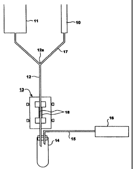
Fig. 1 schiematically illustrates the basic
elements of one form of apparatus constructed in accordance
with the present invention;
Fig. 2 schematically illustrates a system
including apparatus similar to that of Fig. 1 and the main
controls therefor;
Fig. 3 illustrates the basic elements of a second
form of apparatus constructed in accordance with the present
invention;
Fig. 4 is a sectional view along line 4--4 of
Fig. 3;
Fig. 5 is a sectional view along line 5--5 of
Fig. 4;
Fig. 6 is an exploded three-dimensional view
illustrating the magnet holders, and their corresponding
magnets, at one side of the magnetizing station in the
apparatus of Figs. 3-5; and
Fig. 7 illustrates another apparatus constructed
in accordance with the invention.
CA 02333299 2000-11-14
WO 99/59694 PCT/IL99/00255
-6-
DESCRIPTION OF PREFERRED EMBODIMENTS
The apparatus illustrated in Fig. 1 is
particularly useful for magnetically separating certain
types of target cells, such as lymphocytes, red blood cells,
and/or macrophages, from a blood sample.
The illustrated apparatus includes a sample
container 10 to contain the blood sample. Before or after
the blood sample is -introduced into container 10, it is
mixed with magnetic particles, preferably the
commercially-available magnetic microbeads, having a
selective affinity to magnetically stain or label the target
cells in the blood sample within container 10.
The apparatus further includes another container
11 which serves as a supply of a buffer liquid to be used in
the magnetic separation process. The buffer liquid in
container 11 may be any of the commercially-available buffer
liquids, such as normal saline solution, PBS, and the like.
The apparatus illustrated in Fig. 1 further
includes a feed tube 12 for feeding the buffer liquid from
the buffer container 11 through a magnetizing statiori 13 to
a receiving container 14. In the embodiment of Fig. 1 the
feeding of the buffer liquid via feed tube 12 is effected by
gravity and a vacuum. For this purpose, the two supply
containers 10 and 11 are located above the receiving
container 14; and the receiving container 14 includes a
vacuum tube 15 communicating at one end with the interior of
the receiving container, and at the opposite end with a
vacuum source 16.
The blood sample within the sample container 10
includes the magnetically-stained target cells as well as
the non-targetted cells. The blood sample is introduced via
line 17 into an input port 12a in the feed tube 12 at a
location upstream of the magnetizing station 13. However,
before the sample is introduced into the feed tube 12, the
feed tube is first f'illed with degassed buffer liquid from
CA 02333299 2000-11-14
WO 99/59694 PCT/IL99/00255
_7_
container 1, and a predetermined flow rate is effected. The
flow rate is preferably less than one drop per second; a
preferred flow rate is 6-8 drops per minute. Presetting the
flow rate may be effected by controlling the vacuum source
16, or by controlling one or more valves as will be
described more particularly below with respect to Fig. 2.
The buffer liquid from container 11 thus serves as
a continuous liquid carrier for the magnetically-stained
target cells and nori--target cells in the blood sample
introduced from container 10 via the input port 12a, as both
the buffer liquid and the mixture, including the target
cells and non-targetted cells therein, flow via the feed
tube 12 through the magnetizing station 13. Magnets 18 at
the magnetizing station 13 apply a magnetic field across the
feed tube 12 sufficient to separate and retain the
magnetically-staineci target cells within the buffer liquid
at the magnetizing station 13 as the buffer liquid, with the
non-magnetized cells and other constituents of the blood
sample, flows through the output end of the feed tube 12
into the receiving container 14. The receiving container 14
thus receives the buffer liquid together with the
non-targetted cells of the blood sample, since the
magnetically-stained target cells of the blood sample
(including the magnetic particles mixed therein) are held in
stasis by the magnetic flux produced by the magnets 18 in
the magnetizing station 13.
The contents of the receiving container 14 thus
constitute the results of a depletion process performed on
the original sample since these contents include all the
original constituents of the sample except for the
magnetically-stained target cells (and the magnetic
particles added to the original sample in container 10)
which are separated and retained in the magnetizing station
13. Accordingly, the contents of container 14 may be
examined or used for diagnostic, research, or clinical
CA 02333299 2000-11-14
WO 99/59694 PCT/IL99/00255
-8-
purposes in the same manner as when using the results of any
other corresponding clepletion process performed on the
original sample.
If it is also desired to perform a positive
selection process on the original sample (i.e., to use the
separated target cells for diagnostic, research, or clinical
purposes), this may be done by: (a) continuing to feed the
buffer liquid through tube 12; (b) terminating the supply of
the mixture from the sample container 10 and the application
of the magnetic fielci at the magnetizing station 13; and (c)
replacing the receiving container 14 with another rece-iving
container (not shown) to receive the target cells which are
flushed-out by the buffer liquid fed through the feed tube
12. Generally, it would be preferable, after terminating the
introduction of the sample from the sample container 10, to
delay for a short tirne the termination of the application of
the magnetic field at the magnetizing station 13 and the
switch-over of the two containers, to enable the buffer
liquid to rinse-out the magnetically-stained target
particles retained in the magnetizing station 13 before such
particles are flushed-out to the second receiving
container.
Magnets 18 at the magnetizing station 13 may be
permanent magnets which can be physically removed or moved
away from the magnetizing station when flushing out the
magnetically-separated target cells. Alternatively, these
magnets 18 may be electromagnets electrically energized via
connectors 19 (Fig. 2) during the magnetic-separation phase,
and electrically deenergized during the flushing-out phase.
It will be seen that the buffer liquid supplied
from the buffer container 11 provides a constant and
continuous fluid volume, and thereby forms a continuous
liquid carrier for all the constituents of the sample
mixture supplied from the sample container 10. This is true
both during the initial depletion stage, wherein the
CA 02333299 2000-11-14
WO 99/59694 PCT/IL99/00255
9
original sample depleted of the target cells is received
within container 14, and also during the positive selection
stage, wherein the target cells separated and retained in
the magnetizing station 13 are flushed out by the buffer
liquid into another receiving container. The buffer liquid
thus continuously supports both the target cells and the
non-targetted cells during both phases of the separation
process such as to substantially decrease the possibility of
damage or rupture of the cell membranes, as compared to the
conventional MiniMACS process described above. In addition,
and as will be further described below, the method
illustrated in Fig. 1 is highly susceptible to automation to
provide greater through-put capabilities and improved
efficiency in the separation process.
Following is one example of using the apparatus
and method described above with respect to Fig. 1 for
magnetically separating selected target cells from a blood
sample:
A mixed lymphocyte sample was obtained from a
quantity of normal, healthy blood using a normal ficoll
gradient. This sample was split into two groups: control and
experimental. Commercially-available CD19 magnetic
Microbeads (supplied by Miltenyi Biotec GmbH) were added to
the experimental lymphocytes for the purpose of tagging only
B cells in the sample. After staining with the CD19
microbeads, the cells were rinsed twice with PBS.
The separation device was prepared by filling and
rinsing the feed tube 12 with degassed buffer from the
buffer reservoir. Throughout the separation, the system
remains filled with ithe degassed buffer.
The stained lymphocyte mixture was introduced into
the system by way of a lml. syringe (w/o the plunger) with a
0.4x13 needle inserted into a "piggyback site" in the
tubing. The vacuum system maintained a steady flow rate of 6
drops per minute. After all the stained mixture had entered
CA 02333299 2000-11-14
WO 99/59694 PCT/IL99/00255
- 10 -
the system, the needle was removed and the system left to
run until an additional 400 pl of buffer had flowed through
the separation systein. Flow was halted. The receiving tube
was removed, labeled "A", and replaced with a second tube.
The magnetic field was discontinued; flow was
restored; and the linie was flushed with 500 pl of buffer
liquid. Flow was again halted, and this second tube was
removed and labeled "'B"
Cells from the control group and tubes "A" and
"B" were examined in a double blind condition with a light
microscope for membrane condition and cell counts using a
hemocytometer.
There was rio change in cell quality between the
control and the experimental samples. Normally, B cells
comprise 8-11% of the total lymphocyte population. Results
of this separation y-ielded 8.8% B cells, demonstrating the
ability to isolate a specific population with no change in
the cell quality.
Utilizing CD19 microbeads (Miltenyi Biotec GmbH)
to stain for B Lymphocytes, would be expected to produce a
harvest-of approximately 10% from the total lymphocyte
population. The actual results, as examined by light
microscope, CellScan, and FACS, were as follows:
1. A harvest was produced ranging from 8.8% to
11.1%. FACS analysis of these cells revealed a 97% pure
population of desired cells.
2. The membrane quality was unaffected by the
process. This was verified by both light microscope and
CellScan examination.
3. The non-stained lymphocyte populations
(non-targetted cells) were expected to contain approximately
95% T Lymphocytes and comprise approximately 90% of the
total lymphocyte population. FACS analysis of these cells
revealed an average of 93% pure T Lymphocyte populat-ions.
Microscopic examination confirmed that these T Lymphocytes
CA 02333299 2000-11-14
WO 99/59694 PCT/IL99/00255
- 11 -
comprised an average of 90% of the total lymphocyte
population.
In the above-described example, the magnetic field
was produced by permanent magnets of neodymium; the tubing
was 0.80 mm infusion tubing; and the buffer liquid was of
the following composition:
0.15 ml EDTA (Ethylenediarnine tetraacetic acid);
1.10 ml BSA 796 (Bovine serum albumin);
13.75 ml PBS (Phosphate Buffered Saline w/o
caclium and magnesium); yielding
15.00 ml total buffer
Fig. 2 schematically illustrates the basic system
of Fig. 1 but equipped with the main controls for automating
the operation of the system.
Thus, the system illustrated in Fig. 2 includes a
microprocessor controller, generally designated 20, for
controlling the overall operation of the system. The inputs
to controller 20 include a flow selector 21 for presetting
the flow rate of feed of the buffer liquid from the buffer
container 11; an air bubble sensor 22 for sensing the
presence of air bubbles in the buffer feed tube 12; and an
air bubble sensor 23 for sensing the presence of air bubbles
in the sample feed tube 17. These sensors protect the
integrity of the conistant fluid level by shutting dowri fluid
flow (sensor 22 will close valve 27, and sensor 23 will
close valve 28) if an air bubble is detected. Controller 20
also includes an input from a flow rate sensor 29 for
sensing the flow into container 14.
Controller 20 in turn controls the electromagnets
18 at the magnetizirig station 13 via line 24 connecteci to
their connectors 19õ the vacuum source 16 via line 25 and/or
a vacuum valve 26, the feed rate of the buffer liquid via
valve 27 in the feeci line 12, and the feed rate of the
sample via valve 28 in the sample line 17.
CA 02333299 2000-11-14
WO 99/59694 PCT/IL99/00255
- 12 -
Figs. 3-6 illustrate a variation in the
construction of the inagnetic unit in the magnetizing station
13 to enable the magnetizing station to occupy a
substantially longer flowpath of the buffer liquid carrying
the sample, and thereby to increase the throughput and/or
efficiency of the overall separation process. Thus, whereas
in the apparatus illustrated in Figs. 1 and 2, the
magnetizing station 13 occupies a straight length of the
feed tube 12, in Fig. 3 the magnetizing station, therein
designated 30, is constructed to occupy an elongated,
serpentine length of the feed tube 12.
As shown particularly in Fig. 4, the magnetizing
station 30 includes a back mounting plate 31 and a front
mounting plate 32 assembled together by pins 32a in plate 32
received with a friction fit in apertured posts 31a in plate
31. The front mounting plate 31 mounts a plurality of
permanent magnets 33 each carried by a magnetizable core
element 34; and similarly, the back mounting plate 32 mounts
a plurality of permanent magnets 35 each carried by a
magnetizable core element 36.
The permanent magnets 33 and 35 are aligned with
each other, and the magnetizable core elements 34 and 36 are
aligned with each other, so that they define two closed
magnetic circuits, one including air gaps AG1, AG2, and the
other including air gaps AG1, AG3. The feed tube 12 passes
through all three air gaps AG1-AG3, such that the magnetic
field produced by the permanent magnets is effective over a
substantial length of the feed tube.
The back niounting plate 31 is movably mounted by a
pair of rocker arms 37, 38. Each rocker arm includes a
pivotal mounting 37a, 38a to the back mounting plate 31, and
another pivotal mouriting 37b, 38b to a collar 39, 40
slidably received ori pins 41, 42 projecting from a
supporting surface 42. Collar 39 is slideably received on
the upper pin 41, and collar 40 is slideably received on the
CA 02333299 2000-11-14
WO 99/59694 PCT/IL99/00255
- 13 -
lower pin 42 fixed to the supporting surface 43 below pin
41. The two collars 39, 40 are biassed outwardly by co-iled
springs 44, 45 on their respective pins 41, 43.
As shown in Fig. 5, the back plate 31 includes
three apertured posts 31a at the upper end, and three such
posts at the lower end in staggered relationship with
respect to the posts at the upper end. The pins 32a in the
front mounting plate 32 are correspondingly arranged so as
to be received within the apertured posts 31a in plate 31.
Thus, when the front plate 32 is removed, the feed tube 12
may be wound around ithe upper and lower posts 31a of the
back plate 31 in a serpentine fashion (Fig. 5), to produce
downwardly-extending and upwardly-extending stretches 12a-g.
The last downwardly-extending stretch 12g is connected to
the receiving container 14 in Fig. 3.
As shown in Fig. 6, there is one magnet 33, for
each stretch 12a-12g of the feed tube. Since the illustrated
example shows seven such stretches, Fig. 6 illustrates seven
such magnets 33 and their respective core elements 34. There
would be a corresponding number of magnets 35 and core
elements 36 carried by the front plate 32, with the magnets
35 of the front plate aligned with the magnets 33 of the
back plate. As noted above, each pair of magnets and core
elements define three air gaps (AG1-AG3, Fig. 4) for each
stretch 12a-12g of the feed tube, such that the magnetic
field in the magnetizing station is effective over a
considerable length of the feed tube.
Pins 32a of the front plate 32, of the same number
and arrangement as the posts 32a so as to be received within
those posts when applying the front plate 35 to the back
plate 31, are dimensioned to produce a friction fit when the
pins are received within the posts. Posts 31 are also
dimensioned to define a space, shown at 46 (Fig. 4), between
the magnets 33, 35 carried by the two plates 31, 32 for
CA 02333299 2000-11-14
WO 99/59694 PCT/IL99/00255
- 14 -
receiving the respective stretch 12a-12g of the feed tube
12.
After the feed tube has been applied in serpentine
fashion over the apertured posts 31a in the back plate 31,
the front plate 32 is applied by inserting the pins 32a
through the posts 31a. When the pins 32a are received within
the posts 31a, the p-ins engage the collars 39, 40, mov-ing
them towards the fixed surface 43 against springs 44, 45.
The back plate 31 is thus moved by rocker arms 37, 38
towards the front plate 37, to thereby firmly sandwich the
respective stretches of the feed tube 12 between the two
groups of magnets 33, 35.
Fig. 7 illustrates an apparatus similarto that of
Fig. 3, except that the apparatus of Fig. 7 further includes
a mixing chamber 100 at the input port 112a of the feed tube
112 for pre-mixing the sample mixture applied via inlet tube
110, and the buffer liquid applied via inlet 111, before
being fed, via tube 112, to the magnetizing station 130. The
apparatus in Fig. 7-further includes a pump 132, such as a
peristaltic pump, in the outlet end of tube 112 for
controlling the feeding of the liquid therefrom into the
receiving container (14, Fig. 3).
In all the above-described embodiments, the
magnetic field can be controlled according to the particular
application to produce a predetermined field intensity. For
this purpose, the magnetic air gap can be changed when using
permanent magnets: and when using electromagnets, the
current can be varied, e.g., via microprocessor 20 in
Fig. 2.
While the invention has been described above with
respect to selected target cells from a blood sample, it
will be appreciated that the invention could be used in many
other applications for the selection of other target
particles from a body, such as selected proteins, or other
types of particles. Also, while the use of magnetic
CA 02333299 2000-11-14
WO 99/59694 PCT/IL99/00255
- 15 -
microbeads is preferred, it will be appreciated that other
magnetic particles niay be used in the process. Further,
other sensors, such as for radioactivity, conductivity, etc.
can be included. Mariy other variations, modifications and
applications of the invention will be apparent.