Note: Descriptions are shown in the official language in which they were submitted.
CA 02333387 2000-11-24
- 1 -
DEVICE FOF; THE COUPLING OF EXCAVATOR TEETH
SPECIFICATION
The present invention refers to a device for the
coupling of excavator teeth which is applicable to the
buckets of excavating machines and, in general, to the
active working edges of earth-moving machines of similar
types.
Machinea for civil engineering work which effect
the removal of ;:materials such as earth, rocks, etc.,
generally have ac. rive edges on the so-called buckets of
the excavators, which are open receptacles of specific
shape fixed to the supporting and travelling gear of the
machine and which have the function of removing t:h.e mass
of earth or earth and more or less loose stones, by means
of their front edge, collecting in the bucket the
materials which have been loosened, allowing them to be
transferred to a vehicle for their transport to another
site or simply for depositing the mass of earth and stones
which has been removed, for its subsequent replacement,
for example, in t:he case of the opening of a trench.
The buckets of excavators and the like suffer
significant problems at the active edge because of the
high degree of wear to which it is subjected by contact
with the earth and stones, which have very abrasive
characteristics. For this reason, it is necessary to
equip the active edge of the excavator or similar machine
with detachable teeth, which are removable components
which bear the greater part of the wear by being in direct
contact with the mass of earth and stones, and which are
therefore parts which wear out very quickly. Said teeth,
which are parts that can be exchanged fairly frequently,
must combine characteristics which are to a certain extent
contradictory, owing to the fact that, being parts which
are changed frequently on excavating machines and the
like, their price should be relatively low, so it is
necessary to exclude mechanization of the teeth, which
r~
iur,; ~i
CA 02333387 2002-07-17
s
- 2 -
should be manufactured simply by casting or forging high
strength steel. The other contradictory characteristic
lies in the need for the mounting of the tooth on the
tooth-carrier located at the active edge of tree bucket for
excavators or the like to be effected with sufficient
adjustment to avoid as far as possible any play between
the facing regions of the tooth-carrier ancL the tooth,
since the occurrence, otherwise inevitable, of: play in the
said region results in an increase in the stresses at
specific points of contact between the tooth and the
tooth-carrier, which further increase the wear locally; in
a process which may end in breakage of the parts and which
involves changing the worn part, that is i~o say, the
tooth, more or less frequently, according to how the
above-mentioned wear phenomena can be controlled to a
greater or lesser~degree.
At present, many types of coupling between the
teeth of excavators -and the tooth-carriers are known,
although all of them, given the contradictory- conditions
to be fulfilled and the hard work to which said components
are subjected, exhibit defects with regard to what could
be considered an ideal solution in terms of life of the
tooth and avoidance of excessive wear on the tooth-
carrier, enabling the latter to have an acceptably
extended life.
US Patent 5561925 refers to a tooth assembly and
retaining mechanism in which a nose portion matching with
the socket of the tooth has parallel. surfaces
interconnected by a flat end surface.
30 US Patent 4625439 refers to an excavating tooth
retaining means comprising a nose portion in which the
tooth is fixed by means of a wedge in which th<a wear part
lands directly against the holder.
However, none of said patents discloses the
double inverted dovetail structure which characterizes the
present invention.
~. I illl : 1.1 '.,
CA 02333387 2002-07-17
- 3 -
According to the present invention, there is
provided a tooth carrier for being connected to a bucket of
a machine for moving materials, such as earth and rocks, in
order to carry a tooth (4); having a projecting portion (2)
with an at least partly decreasing cross section area
towards its free end (13), said projecting portion being
intended for location at least partly in a cavity of said
tooth, characterized in that each of two E=_nd regions
(12,14) of the projecting portion substantially has the
shape of a parallel trapezoid in cross section, that. a
first (12) of said end regions, which connects the
projecting portion to the tooth carrier body, has the
longer of the two parallel sides of the trapezoid at the
bottom, and that a second (14) of said end regions, which
forms the free end (13) of the projecting portion, has the
longer of the two parallel sides of the trapezoid at the
top.
According to the present invention, there is also
provided a tooth (4) for being connected to a tooth carrier
of a machine for moving materials, such as earth and rocks,
the tooth having a cavity for receiving at least a part of
a projecting portion of the tooth carrier, wherein said
cavity has an at least partly decreasing cross section area
from its mouth towards its inner end characterized in that
each of two end regions of the cavity substantially has the
shape of a parallel trapezoid in cross section, that a
first of said end regions, which forms the mouth of the
cavity, has the longer of the two parallel sides of the
trapezoid at the bottom, and that a second of said end
regions, in the vicinity of the inner end of the cavity,
inr:
1I,
CA 02333387 2002-07-17
- 4 -
has the longer of the two parallel sides of the trapezoid
at the top.
Preferably, the coupling for excavator teeth and
the like which is the subject of the invention is of the
type which has a projection on the front face of the tooth-
carrier, directed substantially axially with respect to the
longitudinal axis of the tooth-carrier, and in which the
cross-section of the tooth coupling region h.as a cross-
section decreasing from the starting region to the free
end, being characterized by the combination of the areas of
contact between the tooth-carrier and the tooth, and the
positioning of the retaining cotter pin, so that a close
coupling is obtained between the tooth and the tooth-
carrier, giving rise to secure fastening, with many areas
of contact between the two coupled componen'~ts, for the
purpose of reducing the local wear and with an arrangement
of angles of the areas of contact such that the stresses
produced on the tooth tend to produce greater wedging and
matching of the tooth with the tooth-carrier. In order to
obtain this result, the area coupling the tooth with the
tooth-carrier has a structure which is constituted
basically by the joining of two reverse dovetail profiles,
that is to say, the dovetail at the first end :region being
inverted compared to the dovetail at the second end region,
corresponding to the starting region and the free end or
point of the so-called "nose" of the tooth-carrier
respectively. This is complemented by a slightly convex
structure, above all of the upper area of junction between
the base or start of the nose of the tooth-carrier and the
end or projection thereof which has a uniform ;section. The
area of junction of the upper curved part of the nose of
i uii
1I
CA 02333387 2002-07-17
- 4a -
the tooth-carrier with the base thereof has a narrow flat
transverse region. The lateral faces of the nose of the
tooth carrier assume the form of facets, one of them
corresponding to the front projection of constant section
and another to the lateral faces, which may be flat or
gently curved with the convexity towards the outside.
with this arrangement the result is obtained
that the nose of the tooth-carrier exhibits a much higher
mechanical strength and, above all, in normal operation
thereof no stresses are produced which tend to E=_ject the
tooth, which constitutes a recurrent problem of the
currently known tooth-carriers. In particular, the
slightly curved structure, with the convexity directed
outwards, of the upper face of the nose of the tooth-
carrier permits, in addition to a very efficient coupling
between the tooth and the tooth-carrier, an increase in
the cross-section of the nose of the tooth-carrier, and
therefore a greater mechanical strength on the l.atter_
Preferably, the device of the present invention
is likewise characterized by a new type of cotter pin for
retaining the tooth on the tooth carrier, which is
distinguished by its easy introduction and high resistance
to removal, basically comprising a body of the cotter pin
of flattened generally parallelepipedal structure, which on
one of its intermediate sized faces has a wide rebate to
which there is joined, by means of vulcanization of special
rubber, an insert carrying a small lateral projection with
rounded transverse edges which is intended to be introduced
into a seating of complementary shape of the tooth-carrier
after its introduction.
For greater understanding there are ap~>ended, by
way of explanatory but non-limiting example, drawings of
a preferred embodiment of the present invention.
CA 02333387 2002-07-17
- 4b -
Figures 1 and 2 are views in elevation and in
plan, respectively, of a tooth-cagier produced according
to the present invention.
Figures 3 to 11 are sectional views through the
CA 02333387 2000-11-24
- 5 -
section planes indicated in Figure 1.
Figures 12 and 13 are respective sections
through the section planes indicated.
Figure 14 is a plan view of the assembly of
tooth and tooth-carrier.
Figure 15 is a longitudinal section in a
vertical plane o:f the assembly of tooth and tooth-carrier
as indicated.
Figure 16 is a perspective view of the assembly
of tooth and tooth-carrier when assembled_
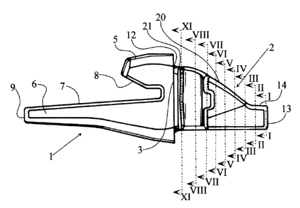
As shown in the Figures, the coupling for
' excavator teeth which is the subject of the present
invention has a fork-like part 1 intended for coupling
with the edge of the excavator bucket and a region 2 that
projects from the rear face 3 of the region 1 and is
intended to receive the excavator tooth, indicated by 4 in
Figures 12 and 14 and in Figures 15 and 16.
The region 1 for the coupling of the excavator
to the bucket is fork-shaped with an upper arm 5 and a
lower arm 6 whic:a are separated by an indentation defined
by flat areas 7 and 8 intended to receive the edge of the
excavator bucket and which in plan have sections
decreasing from the starting region 3 of the coupling 2 to
the free end 9, the upper arm 5 also having flat lateral
faces 10 and 1'.
The 'tooth coupling projection 2 has a
combination of successive regions, which is basically
defined, as will be seen in Figures 3 to 11, by a
structure constituted basically by two inverted dovetails,
that -.s to say, t_he dovetail at the first end reg~~on being
inverted compared to the dovetail at the second end region
corresponding respectively to the starting area '12 of the
tooth and to the and 13 of the projection 14 of the: tooth-
carrier, which correspondingly are complementary to the
cavity of the tooth 4. The said projection 14, as shown
by the sections provided, has a constant section
throughout its 1~=ngth. For this reason, the lateral faces
CA 02333387 2000-11-24
- 6 -
of the nose of the tooth-carrier 2 have a structure
substantially formed by two facets gently differentiated
so that one of t=he laterals corresponds respectively to
the face 15 of the body of the nose of the tooth-~~arrier
and the flat face 16 of the termination of constant
section 14. The other lateral 17 has .similar
characteristics, having a wide indentation in a
substantially vertical arrangement 18, which is intended
to receive the cotter pin 19, which has been ;shown in
greater detail in Figure 15.
The upper face 20 of the nose of the tooth-
carrier has a gE:nerally curved shape with the convexity
directed outwards, joining the inner end of the projection
14 to the body 1 of the tooth-carrier by means of a small
flat area in th.e area of junction with the said body
indicated by 21 in Figure 1 and also in Figure 13.
The lateral faces 15 and 17 may be flat or
curved, with the convexity directed outwards.
The wonstruction of the nose of the tooth-
carrier with the=_ shape indicated makes it possible to
obtain a much hi.ghe~.° strength thereon, at the same time
eliminating the r'actions of ejection of the tooth which
customarily occur in the currently known mountings for
excavator teeth..
As will be observed in Figures 12 and '15, the
cotter pin 19 has a flattened straight, generally
parallelepipedal structure, having on one of it~~ minor
sides a wide indentation 22 in which, by means of a
vulcanized coating 23, there is effected the join.i:ng of a
straight insert 24, carrying a lateral project=ion 25,
provided with rounded edges, which is engaged in a recess
of complementary shape of the nose of the tooth-~~arrier.
This arrangement of the cotter pin therefore
makes possible both its easy introduction by axial
compression in ~.ts groove and sufficient retention. 1=hereof
in the nose of the tooth-carrier. Withdrawal i.s also
facilitated by the existence of the joining part of
CA 02333387 2005-03-O1
~.
_ 7 _
vulcanized rubber.
By means of the arrangement which has been
explained, the coupling device for excavator teeth which
is the subject of the present invention makes it possible
to fit the tooth with minimum play in all the coupling
areas, as well as allowing numerous areas of contact in
order to reduce local wear, and reduces the force
components in the direction of ejection of~the tooth with
respect to the tooth-carrier.
As it is obvious, this invention will cover the
tooth holder as well as the tooth to be adapted to the
same, which will have a form which is conjugated to the
form of the mating tooth holder, with cavities to receive
the coupling device.
The characteristics of the cotter pin are also
very advantageous, both as regards the ease of assembly
and disassembly of the cotter pin and as regards the high
holding force- thereof .