Note: Descriptions are shown in the official language in which they were submitted.
CA 02333396 2000-11-24
WO 00/07050 PCT/tJS99/13920
Fiber Optic Terminus and Manufacturing Method therefor
Related Application
This invention is related to a co-pending, commonly-owned, U.S. Patent
application entitled "Bonding Operation for Fabricating Fiber Optic
Terminus" (Docket No. S-53!x2).
Technical Field
This invention is directed to fiber optic cabling, and, more particularly, to
a
terminus configuration therefor which is less susceptible to damage or
degradation
in a demanding operational environment, e.g., vibration prone environment.
Furthermore, a manufacturing; method, inspection technique, and acceptance
criteria
are disclosed for determining 'the efficacy of the fiber optic terminus.
Background Of The Invention
Fiber optics are increasing being utilized for communicating wide band
widths of data at high data transmission rates. Based upon the material and
labor
costs associated with producing a fiber optic simplex cable, the use of fiber
optics
typically becomes cost efficient (i.e., as compared to conventional metallic
cable)
when the data rates exceed about 100,000 bits per second (bps). Today, the
applications for fiber optics are typically limited to telecommunications,
cable
television, and highly advanced aircraft/spacecraft. With respect to the
latter, fiber
optics are used extensively in the Boeing/Sikorsky RAH-66 Comanche rotorcraft,
the Lockheed Martin/Boeing F-22 fighter aircraft, and NASA's space station
"Freedom". Of course, as the manufacturing methods become automated and
material costs diminish, the use of fiber optics will become more attractive
even for
less demanding data communications applications e.g., the automobile industry.
The principle advantages of fiber optics include weight, material cost, and
size when compared to a conventional twisted-shielded pair of copper wires.
Firstly,
for the same "data-carrying capacity", a fiber optic simplex cable weighs
about
0.0003% of the weight of a conventional twisted-shielded pair. For example, a
ten-
foot length of fiber optic cable having the capacity to transmit data at a
rate of
_1_
CA 02333396 2000-11-24
10-08-2000 S-5393 PCT/US99/13920
about S x 1 Og bps, weighs about 0.009 kg. as compared to about 30.0 kg. for a
copper
wire bundle having the same data carrying capacity. Similarly, the material
cost of
the described ten-foot segment is about 0.07 % of the cost associated with the
comparable length of twist-shaelded pairs. Moreover, the bundle diameter
measures
approximately 0.1586 cm. for the fiber optic cable verses about 12.7 cm. for
the
segment of twisted shielded pairs.
Yet additional advantages, particularly important to the aerospace industry,
include protection against E'.lectro-Magnetic Interference (EMI) and potential
fire
hazards. With respect to the :former, conventional copper wiring used in
aircraft is
heavily shielded for preventing electromagnetic interference or "cross-talk"
between
systems. It will be appreciated that such protection is particularly important
for
aircraft flight critical systems, e.g., an Automatic Flight Control System
(AF'CS),
wherein cross-talk between systems may introduce stray signals into the one of
the
flight critical systems. Fiber optic filaments, in contrast, are not
electrically
conductive, and, consequently, are immune to EMI. With respect to the latter,
the
electrical connections associated with conventional copper wiring can produce
arcing, and, consequently, a ..park which can be a potential fire hazard. It
will be
appreciated that in an aircraft carrying about 30% of its weight in jet fuel;,
the
electrical connections must be; highly protected/insulated and, preferably,
positioned
distantly of fuel tanks/fuel liners. Fiber optic connections, in contrast, do
not produce
arcing, and, consequently, cannot become a source of ignition.
Despite the numerous advantages of fiber optics, several drawbacks persist
with respect to the ruggedness/reliabiIity of the fiber optic cable/termini,
particularly
when adapting fiber optics to a demanding operational environment. That is, it
will
be appreciated that the optical fiber employed in such cables is extremely
delicate
and prone to damage, especialy when adapted for use in a high vibration and/or
high temperature environment:. For example, vibratory stresses can cause a
minor
imperfection, i.e., a small <;rack, introduced in the manufacturing process to
propagate within the optical fiber and cause premature failure of the fiber
optic
cable. It will be appreciated that even small cracks in the optical fiber can
seriously
degrade or entirely defeat the transmission of data communication signals.
-2-
AA/IENDED SHEET
CA 02333396 2000-11-24
10-08-2000 S-5393 PCT/US99/13920
Furthermore, elevated temperatures during the manufacturing process or, in its
operational environment, can introduce thermal stresses in the optical fiber,
which,
similarly, can become the sowrce of imperfections and failure of the optic
fiber.
A need, therefore, exi:;ts to provide a fiber optic cable/terminus which is
less
susceptible to damage or signal degradation when adapted for use in a
demanding
operational environment, e.g., a high vibration and/or high temperature
environment.
EP-A 0 056 192, EP-A 0 058 344, and DE-A 29 10 860 all disclose
connectors for optical fibers in which a fiber is mounted in a ferrule and an
end
surface of the fiber is recessed below a face surface of the female.
US-A 5,216,846 describes a process for grinding the end of an optical fiber
mounted in a female, in which process a succession of abrasives is used, and
each
abrasive is harder and has a finer grit than the one before.
Summary of the Invention
It is an object of the present invention to provide fiber optic terminus for
use
in fiber optic cable connector:. which terminus defines a terminus end profile
which
is less susceptible to damage or signal degradation when adapted for use in a
demanding operational environment.
It is another object of the present invention to provide a manufacturing
method for making such a fiber optic terminus.
It is another object of the present invention to provide an inspection method
for determining the efficacy of the fiber optic terminus.
The invention provides a fiber optic terminus for use in fiber optic cable
connections, said fiber optic terminus including a optical fiber disposed
within and
supported by a female, said fiber optic terminus having a terminus end profile
having
a face surface defined by the ferrule, and an end surface defined by the
optical fiber,
said face surface defining a theoretical plane, the highest point of said end
surface lying below said theoretical plane, characterised in that the lowest
point of
said end surface is a distance within a range of about 0.5 ~,m to about 1.0 ~m
below
said theoretical plane.
-3-
AAIIENDED SHEET
CA 02333396 2000-11-24
10-08-2000 S-5393 PCT/US99/13920
In another embodiment of the invention, the face surface of the female
defines a surface angle which is less than about 2.0 degrees to minimize
transmission losses when a paiir of termini are assembled in opposed relation.
The fiber optic terminus is fabricated by a method including the steps of
stripping a fiber optic cable to expose the optical fiber; bonding the
stripped-end of
the fiber optic cable (8) to a ferrule (24); cleaving said optical fiber (12)
in close
proximity to a face surface (2:8) of said female (24); polishing said cleaved-
end of
said optical fiber ( 12) to a<:hieve a terminus end profile; and inspecting
said
polished-end of said optical fiber (12) to determine whether said terminus end
profile conforms to predefined acceptance criteria; said polishing step being
characterized by: polishing the ferrule (24) and optical fiber (12) utilizing
a coarse
polishing film comprising a soft polishing material, said coarse polishing
film
having a grit size greater than about 5 micrometres; polishing the female (24)
and
optical fiber ( 12) utilizing a fine polishing film having a hard polishing
material,
said fine polishing film having a grit size greater than about 0.1
micrometres; and
polishing the femzle (24) and optical fiber (12) utilizing an ultra-fine
polishing film
having a soft polishing material, said ultra-fine polishing film having a grit
size
greater than about .00I micrometres, said soft polishing material having a
hardness
of about 8.0 to about 35.0 on a Knoop Hardness Scale, and said hard polishing
material having a hardness of .about 45.0 to about 105.0 on a Knoop Hardness
Scale,
whereby said polishing step produces a termini end profile (50) wherein the
lowest
point of an end surface (52) of said optical fiber (12) is recessed below the
face
surface (28) of said female (24E) by a distance (~ within a range of about 0.5
p.m to
about 1.0 Vim.
Preferably, the various polishing films are backed by a rigid substructure to
achieve the desired terminus end profile.
-4-
AA/IENDED SHEET
CA 02333396 2000-11-24
10-08-2000 S-5393 PCT/US99/13920
In yet another embodinnent of the method, the inspection step is characterized
by: examining said terminus e:nd profile using a microscope to detect
imperfections
in the optical fiber, and examining the terminus end profile using an incident-
light
interference device. In the preferred embodiment, a white-light interference
device
is used to examine the terminus end profile.
Brief Description Of The Dr;~wings
A more complete understanding of the present invention and the attendant
features and advantages thereof may be had by reference to the following
detailed
description of the invention when considered in conjunction with the following
drawings wherein:
Fig. 1 depicts a fiber optic simplex cable employing a fiber optic tezzninus
according to the present invention;
Fig. 2 depicts an end of a fiber optic cable which has been stripped in
accordance with a first manufacturing step in the fabrication of the fiber
optic
terminus;
Fig. 3 depicts the stripped end of the fiber optic cable in preparation for
bonding to a female assembly;
Fig. 4 depicts the integrated fiber optic cable/ferrule assembly subsequent to
the bonding operation;
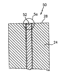
Fig. 5 depicts a preferred terminus end profile subsequent to a polishing
operation wherein the end surface of the optical fiber is undercut relative to
a face
surface of the female assembly;
Fig. Sa depicts an enlarged view of Fig. 5 for illustrating the end surface of
the optical fiber and a maximu~rn acceptable undercut relative to a
theoretical plane;
-4a-
AMENDED SHEET
CA 02333396 2000-11-24
10-08-2000 S-5393 PCT/US99/13920
Fig. Sb depicts an end view of the terminus end profile of Fig. Sa;
Fig. 6 depicts termini according to the present invention disposed in opposed
relation for illustrating an alternate embodiment of the invention wherein a
maximum acceptable surface angle is defined for minimizing transmission
losses;
Fig. 7 is a simplified view of a polishing film having a rigid support or
backing for producing the desired undercut terminus end profile according to
the
present invention;
Fig. 7a is an enlarged view of Fig. 7 for illustrating the function of the
rigid
support;
Fig.8 depicts an interferometer (Michelson-type) used to inspect the
topography of the resultant terminus end profile subsequent to the polishing
operation.
Fig.9 depicts a tvro-dimensional fringe pattern generated by the
interferometer, which fringe pattern is indicative of the topography of the
terminus
end profile;
Fig. 10 is a three-dirr.~ensionaI representation of the terminus end profile
which is produced by the interferometer;
Fig. 11 depicts electronc masks projected upon the terminus end profile for
interpreting the topography thereof and for simplifying the complexity of
computer
calculations used to compare tlhe topography against predefined acceptance
criteria.
Best Mode For Carrying Out The Invention
Referring now to the drawings wherein like reference characters identify
corresponding or similar elements throughout the several views, Fig. 1 shows a
fiber
optic simplex cable assembly 6 comprising a fiber optic cable 8 and a fiber
optic
terminus 10 according to the present invention disposed at the each end
thereof.
Such termini 10 are used to produce the fiber optic connections between pairs
of
simplex cables 6 and are typically aligned end-to-e:nd or face-to-face by
means of a
conventional pin and socket arrangement. In the context used herein, a "fiber
optic
te:rnlinus" means at least the combination of an optic fiber or filament
disposed
within and supported by any h~ard/rigid structure useful for protecting the
tip end of
-5-
AA/IENDED SHEET
CA 02333396 2000-11-24
10-08-2000 S-5393 PCT/US99/13920
the optical fiber (such structure will hereinafter be referred to as a
"ferrule" or
"ferrule assembly"). As will be discussed in greater detail below, each
terminus 10
is manufactured and assemt~led to highly precise specifications to optimize
the
spectral transmission across the fiber optic connection, i.e., minimize loss.
For
aerospace applications, the acceptable loss across a fiber optic connection is
typically less than about 1.0 decibels.
The manufacturing method for producing the inventive fiber optic
terminus 10 involves several critical steps which will be illustrated and
described
below. While the fiber optic; terminus 10 will be described and illustrated in
the
context of a "pin" terminus, it should be understood that the inventive
teachings are
equally applicable to "socket" terminus or other terminus configurations. The
steps
involved in the manufacture: of any epoxy-style fiber optic terminus include:
stripping the fiber optic cable to expose various internal elements of the
cable,
bonding the cable to a female: assembly, cleaving and polishing the end face
of the
optical fiber such that it is substantially co-planar with the face surface of
the ferrule
assembly, and inspecting the end face of the optic fiber for imperfections. In
one
embodiment of the present invention, the bonding operation is characterized by
solidifying the bonding adhesive about an inboard end portion of the ferrule
assembly and, subsequently, fully curing the bonding adhesive in the terminus.
Preferably, the final cure operation is performed by a mufti-stage cure cycle
or a
"stepped-cure'" operation. In another embodiment of the invention, the
polishing
process comprises the use of hard and soft polishing films having a select
particulate
size, e.g., course, intermediate, and fine, to produce a preferred terminus
end profile.
The preferred terminus end profile is defined in relation to the face surface
of the
female assembly and is characterized by the optical fiber defining an end face
which
is undercut relative to the face surface of the female assembly. In yet
another
embodiment of the invention, a white light interferometer in combination with
a
preprogrammed software routine is used to characterize the entire surface of
the end
profile and to determine whether the end profile conforms to predefined
acceptance
criteria. The import of these features of the invention with be described in
subsequent paragraphs.
-6-
AMENDED SHEET
CA 02333396 2000-11-24
WO 00/07050 PCT/US99/13920
Stripping Operation
In Fig. 2, the fiber optic cable 8 is stripped to remove and expose several
sheaths of cable material. lDescribing the fiber optic cable 8 from its
innermost
element to its outermost sheath, the stripped end of the fiber optic cable 8
comprises
a central optical fiber 12, a silicon buffer 14 disposed about the optical
fiber 12, an
inner jacket 16 enveloping the silicon buffer 14, a strengthening member 18
comprising a braided or woven fiber, e.g., a polyamide fiber such as Kevlar~,
wrapped about the inner jacket 16, and an outer jacket 20 enveloping the
strengthening member 18. Tlhe fiber optic cable 8 may be stripped by hand
using a
conventional mechanical stripper such as that available from Clauss Inc.,
located in
Freemont, OH, or by automated stripping equipment such as that produced by
Schleuniger Inc., located in Manchester, NH. The dimensions for stripping each
sheath will vary depending upon the type of terminus being fabricated and,
more
specifically, upon the dimensions of the ferrule assembly to be bonded to the
stripped end of the fiber optic cable 8.
Bonding Operation
In Fig. 3, the stripped end of the fiber optic cable 8 is prepared for bonding
to
a ferrule assembly 22. In the described embodiment, the ferrule assembly 22
includes a rigid ferrule 24 and an aft body or sleeve 26 circumscribing and
bonded to
an end portion of the ferrule 24. More specifically, the rigid ferrule 24
defines an
external face surface 28, a central bore 30 and an internal end 32, and the
aft body 26
comprises an cylindrical inner bore 34 and a tapered end 36 defining a
cylindrical
outer surface 38. In the described embodiment, the ferrule 24 is fabricated
from a
ceramic such as zirconia, and the aft body 26 is fabricated from stainless
steel.
In preparation for bonding, a bead or ring of bonding adhesive 40 is applied
to the outer surface 38 of the aft body 26, corresponding to region A, and a
layer of
bonding adhesive 42, corresponding to region B, is applied to the optical
fiber 12
and inner jacket 14. In the broadest sense of the invention, the bonding
adhesives
40, 42 in regions A and B arc: the same and, furthermore, are selected such
that: the
Glass Transition Temperature (T~) is greater than the maximum temperature
CA 02333396 2000-11-24
WO 00/07050 PCT/US99/13920
anticipated in the operating environment of the terminus 10. In the described
embodiment, the bonding adlhesive is a thermosetting epoxy having a T~ of
greater
than about 125° C which represents the maximum temperature anticipated
in
aerospace applications. A suitable thermosetting epoxy is available from EPOXY
TECHNOLOGY, INC. located in Billerica, MA under the tradename F?PO-
TEK 353ND. Furthermore, prior to bonding, the strengthening member 18 is
folded
rearwardly over the outer ,jacket 20. In the preferred embodiment, a shrink
tubing 44, which will subsequently overlay the strengthening member 18, is
used to
temporarily preposition the strengthening member 18 over the outer jacket 20.
In Fig. 4, the stripped end of the fiber optic cable 8 is inserted within the
ferrule assembly 22 such that the optical fiber I2 passes through the ferrule
bore 30
and the inner jacket 14 abuts the internal end 32 of the ferrule 24. Next, the
shrink
tubing 44 is slid rearwardl~r (shown in phantom) to release the strengthening
member 18 which is then folded over the cylindrical outer surface 38 of t:he
aft
body 26. As such, the ring; of bonding adhesive 40 in region A contacts and
impregnates the strengthening member 18. The shrink tubing 44 is then
transpositioned such that it overlays the strengthening member 18 and the
outer
jacket 20 of the fiber optic cable 8.
Upon positioning the ahrink tubing 44, the area corresponding to the bead of
bonding adhesive 40 in region A is exposed to a temperature suitable to
solidify the
adhesive 40. In the context used herein, the term solidify means that the
adhesive is
either fully or partially cured and has achieved at least about 20% of its
strength
properties. In the described c;mbodiment, a heat gun (not shown) is used to
elevate
the temperature of the bonding adhesive 40 to between about 175°C to
about 250°C
for a period of less than about 5 minutes. In addition to solidifying the
bonding
adhesive 40, the shrink tubing; 44 contracts so as to effect an improved bond
between
the strengthening member 18 and the ferrule assembly 22 and, furthermore, grip
the
outer jacket 20 of the fiber optic cable 8. Moreover, the shrink tubing 44
provides a
degree of strain relief between the ferrule assembly 22 and the fiber optic
cable 8. A
suitable shrink tubing 44 may be fabricated from a chlorinated polyolefin
material
_g_
CA 02333396 2000-11-24
WO 00/07050 PCT/US99/13920
and is available from Raychem Corporation located in Fremorit, CA under the
tradename Thermofit NTFR Sumitube R10.
The partially bonded assembly is then placed into an oven to fully cure or
cross-link the bonding adhesive 42 in region B between the ferrule 24 and the
optical
fiber 12 and, if necessary, the bonding adhesive 40 between the strengthening
member 18 and the aft body 2 6. Preferably, the assembly is exposed to a mufti-
stage
cure cycle or a "stepped-cure" to fully cure or cross-link the bonding
adhesive in
regions A and/or B. In the broadest sense of the invention, the bonding
adhesive 42
is: exposed to a first low dwell temperature for a prolonged period to permit
the
bonding adhesive to set or stabilize, subsequently exposed to several
successively
higher intermediate dwell temperatures, and lastly, permitted to cool down to
a final
low dwell temperature. In the preferred embodiment, the first and final low
dwell
temperatures are about room temperature or between about 22°C to about
28°C.
Furthermore, in the context used herein, the "setting" or "stabilizing" of the
adhesive
means that the adhesive has achieved greater than about 50% of its final
strength
properties.
While the time/tempe:rature cycles may vary depending upon the physical
properties of the selected bonding adhesive, the preferred stepped-cure
operation
comprises five stages as summarized in Table I below.
TABLE I
Cure Stage Tennperature (degreesDwell Time (Minutes)
C)
First 25 ~ 10 120 - 240
Second 80 ~ 10 60 ~5
Third 120 t I 0 60 t5
Fourth 150 X10 60 ~5
Fifth (Cool Down)25 ~ 10 60 (minimum)
The above-described bonding operation offers several advantages which
heretofore have not been addressed/recognized. Firstly, by solidifying the
bonding
adhesive 40 about the aft end. of the ferrule assembly 22, the assembly is
stabilized
-9-
CA 02333396 2000-11-24
WO 00/07050 PCT/US99/13920
for subsequent handling, i.e.., before being placed in a curing oven.
Secondly, the
solidified adhesive 40 in region A provides a damming effect which prevents
"wicking" of adhesive 42 in region B into the strengthening member 18. That
is, the
inventors discovered, in prior unsuccessful bonding attempts, that upon
liquification
of the adhesive in the terminus, i.e., when elevated temperatures caused the
adhesive
to "flow", the braided fibers of the strengthening member 18 would tend to
wick the
adhesive from the interior of the ferrule assembly 22. As such, the wicking
action
depleted the bonding adhesive from the areas most critical to the bonding
operation,
i.e., between the ferrule 24 and the optical fiber 12.
Finally, the stepped-cure operation reduces the residual stresses in the
optical
fiber 12 and maximizes the strength of the bonding adhesive. With respect to
the
former, the inventors discovered that when applying a conventional cure cycle,
i.e.,
elevating the temperature of t:he adhesive to one temperature for a prolonged
period
of time, the bonding adhesive cross-links when the differential in thermal
expansion
between the optical fiber and the ferrule is greatest. As such, when the fiber
and
ferrule cool, residual tensile stresses are placed in the optical fiber which
may
accelerate the propagation of a crack in the optical fiber. In contrast, the
stepped-
cure operation permits the bonding adhesive 42 in region B to dwell at a low
temperature for a prolonged period, i.e., between 1 and 2 hours, to partially
set
before being exposed to yet higher temperatures. As such, while the
differential in
thermal expansion may introduce a transient compressive stress in the optical
fiber 12 during the manufacturing process, when cooled, the optical fiber 12
is
substantially unloaded. With respect to the latter, the inventors discovered
that when
applying a conventional cure cycle, i.e., elevating the temperature of the
adhesive to
one temperature for a prolonged period of time, the Glass Transition
Temperature of
the adhesive may not reach or exceed the maximum anticipated temperature of
its
intended operating environrr~ent. While for many applications this may be an
infrequently-encountered, tolerable transient condition, such resultant
physical
properties of the adhesive may cause "pistoning" of the optical fiber 12
relative to
the ferrule 24. As such, in use, the position of optical fiber 12 may extend
beyond
- 10-
CA 02333396 2000-11-24
WO 00/07050 PCT/US99/13920
the ferrule 24, which, as will be discussed hereinafter, is unacceptable for a
fiber
optic terminus in a demanding operational environment.
Cleaving and Polishing Operation
Once the fiber optic cable 8 and ferrule assembly 22 have been fully-cured,
the end of the optical fiber 12 is cleaved in close proximity to the external
face
surface 28 of the ferrule 24. :More specifically, the optical fiber 12 is
scored/scribed
to create a stress concentration point, and pulled under tension to cleave the
optical
fiber 12. The cleaving operation should break the optical fiber 12 as close as
practicable to the external facie surface 28, and preferably, within about
0.0254 cm.
thereof. Alternatively, the cleaving operation may be rendered moot depending
upon the accuracy of the previously-described stripping operation. That is,
for
example, when using a highly precise automated stripper, the silicone buffer
14 (see
Fig. 2) and inner jacket 16 may be removed so as to effect the precise optical
fiber
length needed, i.e., the lengtlh required for the optical fiber 12 to protrude
a small
1 S amount beyond the external face surface 28 of the ferrule 24.
The polishing operation comprises the use of various sanding materials
(hereinafter referred to as polishing films) to produce a preferred terminus
end
profile. Before discussing thc; polishing operation in detail, it is useful to
define the
geometry of the resultant end profile and the advantages thereof . More
specifically,
and referring to Figs. 5, 5a and 5b, the preferred end profile 50 is
characterized by
the optical fiber 12 defining an end surface 52 which is recessed or undercut
relative
to the face surface 28 of the ferrule 24 (best shown in Fig. 5a). As used
herein,, the
term "end surface" of the optical fiber means at least the combination of the
light-
carrying core 12~o and its suwounding cladding 12~,..
In the broadest interpretation of the invention, the external face surface 28
defines a first theoretical plane P~:S in three dimensional space, which plane
PF$
intersects at least three apexes on the face surface 28. Referring to Figs. 5a
and 5b,
an apex 54 (not shown in Fig. 5a) may be selected from within each of three
120
degree sectors 28S of the face surface 28. In relationship to the plane PFS,
all points
on the end surface 52 of the optical fiber 12 lie below the plane PFS, or
stated another
CA 02333396 2000-11-24
WO 00/07050 PCT/US99/13920
way, no point on the end surface 52 intersects the plane P,:S. In the
preferred
embodiment, a second theoretical plane PBF is defined by a best fit curve,
e.g., Least
squares fit, of the data points associated with the face surface 28. In this
embodiment, it is desirable that the highest point or apex 56 of the end
surface 52
lies below the second planar boundary PBF. Moreover, in this embodiment, it is
desirable to ensure that the lowest point 60 or nadir of the end surface 52
defines a
distance X which is within a range of about 0.01 micrometers to about 10.0
micrometers from the plane PRF, and, more preferably, within a range of about
0.5
micrometers to about 1.0 micrometers therefrom. In the most preferred
embodiment, the apex 56 of the end surface 52 lies below or is mathematically
less
than the lowest point or nadir (not depicted) of the face surface 28. As such,
in
operation, i.e., when a pair of opposed termini are assembled, the optical f
ber 12 of
one terminus 10 will not touch or contact any surface, e.g., the optical fiber
or ferrule
of an opposed terminus.
The inventors discovered that such non-contacting relationship is critical
when adapting fiber optic termini for use in a demanding operational
environment.
Heretofore, fiber optic termini were fabricated so as to produce a protruding
rounded
or, alternatively, planar end profile wherein physical contact between the
optical
fibers is desirable. For example, in the telecommunications industry, the end
profile
is characterized by a rounded end which protrudes slightly with respect to the
face
surface of the ferrule. When assembled, the optical fibers are in physical
contact
which ensures the efficacy of the light transmission. While such relationship
can
enhance the quality of the spectral transmission, physical contact can promote
cracks
and imperfections, especially when subject to a demanding environment. As
mentioned in the Background of the Invention, even minor imperfections can
degrade or entirely defeat the 'transmission of light.
For applications wherein the loss of transmission at each fiber optic
connection is highly critical, the inventors discovered that the surface angle
of the
ferrule is also an impartant factor. In Fig. 6, the face surface 28 of the
ferrule 24
should define a low angle relative to a plane PN normal to the longitudinal
axis 12A
of the optical fiber 12. In accordance with this embodiment of the invention,
the
-12-
CA 02333396 2000-11-24
10-08-2000 S-5393 PCT/US99113920
face surface 28 defines a theoretical plane PB~ generated by a best fit curve,
e.g., a
least squares fit, of the profile data points. Preferably, the plane PB~
defines a
surface angle ~ relative to the plane PN where the surface angle ~ is a
function of a
desired maximum separation distance between two abutting termini 10 and the
radius of the ferrule 24. The following expression may be used to calculate
the
surface angle c~.
~ = Tan:' (M/2r)
wherein M is the maximum separation distance between opposed termini 10;
and
wherein r is the radius r of the ferrule 24.
In the preferred embodiment of the invention, to achieve the loss levels
typically required in the aerospace industry, the maximum separation distance
M is
typically less than about 30 microns, and, more preferably, less than about 10
microns and best at zero rrucrons. For example, when employing the above
expression and criteria, a ferrule having a radius of about 0.0794 cm will,
preferably,
define a surface angle of less than about 2.0 degrees and, more preferably,
less than
about 0.5 degrees and best at ;aero degrees. Accordingly, by maintaining a
threshold
surface angle c~, the gap and degree of light refraction between assembled
termini 10
are minimized so as to mitigate light losses thereacross.
Returning to our discussion of the manufacturing process, the polishing
operation comprises the use of hard and soft polishing films having a select
particulate size, e.g., course., intermediate, and fine, to produce the
preferred
terminus end profile described above. In the broadest sense of the inventian,
the
method involves a first step of polishing the ferrule and optical fiber
utilizing a
course polishing film comprisiing a relatively soft polishing material. In the
context
used herein, "course" means tlhat the particulate or grit size of the
polishing film is
greater than about 5 microns, and the term "soft" polishing material means
that the
particulate material has a hardiness of about eight (8) to about thirty-five
(35) on a
Knoop Hardness scale. A second step comprises polishing the ferrule and
optical
fiber utilizing a "fine" polishing film having a relatively hard polishing
material. In
-13-
AMENDED SHEET
CA 02333396 2000-11-24
10-08-2000 S-5393 PCT/US99/13920
the context used herein, "fine" means that the particulate or grit size is
greater than
about 0.1 microns, and the team "hard" polishing material means that the
particulate
material has a hardness of about forty-five (45) to about one hundred and five
(105)
on a Knoop Hardness Scale. ,A final step in the polishing process involves
polishing
the ferrule and optical fiber utilizing an "ultra-fine" polishing film having
a
relatively soft polishing mateoal. In the context used herein, an "ultra-fine"
means
that the particulate or grit size of the polishing film is greater than about
0.001
microns. In the preferred embodiment, the course polishing film has a grit
size
greater than about 10 microns, the fine polishing film has a grit size greater
than
about 0.3 microns, and the ultra-fine polishing film has a grit size greater
than about
0.05 microns. Furthermore, in the preferred embodiment, the soft polishing
material
is Aluminum Oxide having a Knoop Hardness of between about thirteen (;13) to
about twenty-one (21), and the hard polishing material is Diamond having a
Knoop
Hardness of between about fiflty-six (56) to about one hundred and two {102).
These polishing steps produce the preferred undercut terminus end profile.
In addition to the use of select polishing films, the inventors discovered
that the
undercut end profile is best: achieved by rigidly backing the polishing films.
Heretofore, the polishing films for fabricating prior art fiber optic termini
were
supported by a compliant substructure or backing to produce the desired
protruding/rounded end configuration. In Figs. 7 and 7a, the terminus end
profile of
the present invention is produced by providing a rigid backing 60 to support
the each
of the various polishing films 62. As such, under applied pressure, the
polishing
films 62 deform into the sofiter optical fiber 12 to produce the desired
undercut
configuration.
While the polishing operation described above comprises at least three steps,
it will be appreciated that additional intermediate polishing steps may be
desired to
ameliorate the efficacy of the e;nd profile. Furthermore, the polishing
operation may
be performed by hand, machine or a combination thereof. Table II below
itemizes
an exemplary polishing operation in accordance with the teachings of the
present
invention.
-14-
AAAENDED SHEET
CA 02333396 2000-11-24
WO 00/07050 PCT/US99/13920
Polishing Time (sec) Pressure Polish Grit
Step (gm/mm2) (microns) Material
Hand Polish As RequiredOperator 15 Alum. Oxide
Fixture Hand10 - 30 Operator 15 Alum. Oxide
Polish
Machine 120 25 - 150 10 Alum. Oxide
Polish
Machine 120 25 - 150 3 Diamond
Polish
Machine 90 50 - 305 0.3 Diamond
Polish
Machine 120 100 - 610 0.05 Alum. Oxide
'
Polish
Inspection and Acceptance Operation
Upon completion of the polishing operation, the terminus end profile is
inspected to reveal imperfections and verify that the previously-described
undercut
and/or surface angle is achieved. Such inspection is performed by a
combination of
microscopic visual inspection and by an incident-light interference device
(interferometer). In the preferred embodiment, a high-power microscope e.g.,
500
power enlargement, is employed to examine for imperfections, e.g., cracks,
which
may impede the transmission of light. Generally, any visible crack in the
light
carrying core 120 (see Fig. 5a) of the optical fiber 12 is unacceptable and
results in
rejection of the terminus 10.
Referring to Figs. 8 and 9, once it has been determined that the optical
fiber 12 is free of imperfections, a red- or white-light interferometer 70 is
used to
verify the undercut and/or the surface angle of the terminus end profile. An
interferometer is typically used to develop a pattern of fringes 72 (see Fig.
9)
representative of the geometry of the terminus end profile. A red-light
interferometer uses a single wave-length of light to form a single series of
interference fringes. While a red-light interferometer can be used, one
drawback
thereto relates to its inability to detect step changes in height like those
which can be
found at the boundary between the edges of the ferrule 24 and the optical
fiber 12.
-15-
CA 02333396 2000-11-24
WO 00/07050 PCT/US99/13920
Consequently, additional analysis must be performed to determirie that the
fringe
pattern 72 is indicative of a recess as compared with a protrusion of the end
face 52.
A white light interferometer.. on the other hand, obtains much more
information
about surface structure and can detect step changes in height inasmuch as it
examines several discreet interference bands within the white light spectrum.
Fig. 10 depicts the output of an interferometer which can be mathematically
manipulated to generate a 3-diimensional image of the terminus end profile 50.
To perform this operation, and referring to Figs. 8 and 11, a calibrated V
block (not shown) holds the: terminus 10 in fixed relation to the white light
interferometer, shown schematically above the terminus 10 in Fig. 8. A light
source 75 projects white light onto the terminus end profile 50 through a
splitter 76
(i.e., partial transmission mirror). The light is reflected to a receiver
(shown as an
integral unit with the light source 75) and interpreted via a computer
processing
unit 78. A computer software routine is run internally of the computer
processing
unit 78 to delineate areas corrcaponding to the end face 52 of the optical
fiber 12 and
the face surface 28 of the ferrule assembly 24. More specifically, electronic
t3elds-
of view 80 (see Fig. I I ) are generated to examine regions of the terminus
end
profile 50 to acquire topographical data. For example, a circular field-of
view 82
corresponding to the end surface 52 of the optical fiber 12 is generated for
the
purpose of obtaining topographical data in this area. Alternatively, an
annular field
of view $4 is generated to examine the face surface 28 exclusive of the center
and
peripheral portions of the terminus end profile S0. The computer algorithms
for
generating electronic masks o:F the type described, i.e., for differentiating
the surface
characteristics of one region rc;lative to another, is well-known in the art
and will not
be described in detail herein. Suffice to say that these electronic fields-of
view 80
are generated to collect the most relevant topographical information in a
specific
region.
Once the relevant infomnation has been obtained, the interferometer performs
straight-forward calculations to determine the undercut and/or surface angle
of the
end profile. More specifically, the interferometer may first determine whether
any
point on the end surface intersects a theoretical plane, i.e., the plane PFS
or the plane
- 16-
CA 02333396 2000-11-24
10-08-20C10 S-5393
PCT/US99/13920
PBF (Figs. Sa and 6) discussed in preceding paragraphs. Furthermore, it may
perform
a mathematical determination that the highest point on the end face is below
the
lowest point on the face szu:face. Moreover, a measurement of the maximum
undercut depth X (Fig. Sa) will be determined. Yet other calculations may
include a
determination of the surface angle ~ (Fig. 6) of the end profile.
-17-
AMENDED SHEET