Note: Descriptions are shown in the official language in which they were submitted.
CA 02333583 2002-O1-17
REAL TIME BRACHYTHERAPY SPATIAL REGISTRATION AND
VISUALIZATION SYSTEM
The present invention is directed in general to an improved method and
apparatus for carrying out minimally invasive treatments of the human body by
virtual
reality visualization of the treatment area. More particularly the invention
is concerned
with use of an apparatus and method for providing real time images of a human
anatomy
undergoing treatment along with rapid radiation seed therapy planning and
rapid
performance of therapy including an automatic seed loading methodology which
enhances
therapeutic treatment with greatly improved efficiency both in terms of time
and resources.
New minimally invasive surgical procedures are most often optically guided,
but such optical guidance methods do not permit visualization and guidance of
instruments
or probes within (inside) the target tissue or organ. Incorporation of real-
time three-
dimensional visualization inside diseased tissues would provide accurate
guidance of
therapy. Open-magnet MItI is used to visualize some procedures such as thermal
therapy
and brain biopsies. However, the method is expensive, not truly real-time and
is limited
in application.
Numerous conventional treatment methods involve attempts to provide a
targeted dosage of radiation or chemicals to the organ and such treatments are
often based
on general anatomical assumptions of size and location. These methods suffer
from
inaccuracy of localizing the target for any one particular individual and
potential real time
changes of relative orientation and position of target tissue, normal tissue
and radiation
therapy devices.
It is instructive in explaining the invention to consider one specific type of
exemplary condition, adenocarcinoma of the male prostate which is the most
commonly diagnosed cancer in the male population of the United States. At
present,
254,000 new cases of prostate cancer were diagnosed in 1995 and 317,000 in
1996.
In the 1960's, a method of implanting radioactive gold or iodine seeds was
developed.
With this approach, the radioactive material is permanently placed into the
prostate via
CA 02333583 2000-11-27
WO 99/60921 PCT/LJS99/11847
a retzopubic approach during laparotomy when diagnostic lymphadenectomy was
also
being performed. A high dose of radiation is delivered to the prostate as the
radioactive seeds decay. In several reports, the .five year disease free
survival ("local
control") obtained by this method was compared to similarly staged patients
treated
with an external radiation beam. In view of this, gold was replaced by I'''
implantation for safety of personnel doing implantation. Except for early
stage
prostate cancer (T2a tumors), inferior rates of local control are reported
with "free
hand" I25-Iodine implantation. There was significant dose inhomogeneity due to
the
nonuniformity of seed placement. leading to underdosing of portions of the
prostate
gland and significant complications due to overdosing of adjacent healthy
tissue
structures. The poor results for local control and normal tissue complication
were
attributed to the doctor's inability to visualize and hence control where the
radioactive
seeds were actually being deposited inside the patient.
Recently, transrectal ultrasonography ("TRUS") has been used to visualize
125-Iodine seed placement during transperineal implantation. The early
reported rates
of serious late complications is higher than external beam therapy. Even with
this
technique, significant imprecisions in seed placement are observed. Due to the
proximity of the prostate to the rectum and bladder, incorrect seed placement
may lead
to serious overdosing of these structures and late complications.
The recent transrectal ultrasound guided transperineal implant technique has
been developed which is in use. 'that procedure is described in three steps:
(1 ) the
initial volumetric assessment of the prostate gland performed using
ultrasound, (2)
development of a radiation therapy "pre-plan," and (3) performing the actual
intraoperative implant. The purpose of the initial volumetric assessment prior
to the
pre-plan or implantation is to obtain a quantitative; understanding of the
size of the
prostate, which is then used to determine the total activity and distribution
of
radioactivity which is to be implanted into the prostate. To perform the
assessment.
an ultrasound probe is physically attached to a template. The template is a
plastic
rectangle which contains an array of holes separated at predefined intervals.
usually ~
mm. The template system serves two purposes: (1 ~ to fix the ultrasound probe,
and
hence the imaging plane to the reference frame of the catheter and seed
positions, anil
CA 02333583 2000-11-27
WO 99/60921 PCT/US99/11847
(2) to guide the catheters into the prostate volume. More specifically, the
template
system serves as a reference frame for spatial quantities which are required
for the
description of the implant procedure. Using transrectal ultrasound, a number
of serial
ultrasound images are obtained at 5-mm intervals, and the prostate is outlined
on each
image. The images are taken so that the entire prostate gland is covered. This
results
in a stack of two-dimensional outlines, or contours, which, taken together,
outline the
entire three-dimensional prostate volume. From this volume, the quantitative
volume
of the prostate is calculated.
Once the three-dimensional contour data has been obtained for the prostate
volume, a radiation therapy plan which describes the positions of the
radioactive seeds
within the prostate is developed. This plan attempts to optimize the dose to
the
prostate, minimize the dose to surrounding healthy tissue, and minimize dose
inhomogeneity. 'The positions of the radioactive seeds are constrained to fall
within
the catheter tracks, since the seeds are placed within the prostate
transperineally via
these catheters. 'fhe result of the pre-plan describes the positions and
strengths of the
radioactive seeds within the catheter which optimizes the dose to the
prostate.
Intraoperatively, the TRtlS probe is inserted, and the template is mounted
against the perineum. As previously described, the template is a plastic
rectangle
which contains an array of holes separated at fixed intervals. These holes act
as
guides for the catheters. The TRUS probe is inserted into the rectum and
placed so
that the image corresponds to the prostate base (the maximum depth). Two or
threC
catheters are inserted into the tissue surrounding the prostate or in the
periphery of the
prostate to immobilize the gland. These catheters contain no radioactive
seeds. This
image serves as a spatial reference for all further images and seed positions
within the
prostate. Subsequently, catheters are inserted into the gland based on the pre-
plan
through the template . The ultrasound probe is positioned each time so that
the
catheter, and hence seeds, which are inserted into the prostate are visible on
the
ultrasound image. If the placement of the catheter within the prostate is not
according
to the pre-plan, the catheter is then withdrawn and reinserted until the
catheter is
correctly placed. This is a time-consuming process; and it is very difficult
to achieve
optimal placement. Invariably, the catheters deflect angularly as they are
inserted, and
_3_
CA 02333583 2002-O1-17
their positions are difficult to determine by two-dimensional ultrasound. This
is due to the
fact that the visualization process is a two-dimensional process while the
actual implant
procedure is three-dimensional. Once all the seeds are in place, another
series of two-
dimensional images are obtained to quantify the final, resultant dose
distribution delivered
to the patient. In some instances. a pair of orthogonal fluoroscopic images
are also
obtained to determine the final seed placements. 'this procedure is usually
performed a
few weeks post implant.
These above described prior art systems suffer from inherent inaccuracy, the
inability to correct the positioning of the radioactive seeds without repeated
withdrawal
and reinsertion of seeds into the prostate and are not real time manipulations
of the
therapeutic medium. Further, the overall positioning of the template and
patient may be
different during treatment compared to the assessment phase. Consequently, the
catheter
position and seed position may be at an undesired position relative to the
presumed
assessment phase location.
Accordingly the invention seeks to provide an improved system and method for
invasive treatment of the human body.
Further the invention seeks to provide a novel system and method for real time
and/or near real time, three-dimensional visualization of a human organ
undergoing
invasive treatment.
Still further the present invention seeks to provide a more precise and
accurate
implant placement for radiation therapy, thermal therapy and surgical
ablation.
Further still the invention seeks to provide an improved system and method for
generating a three-dimensional image data set of a human organ for a treatment
protocol
using a real-time ultrasound imaging system with spatial landmarks to relate
the image
data set to present time, invasive treatment devices.
Further still the invention seeks to provide a novel system and method for
spatial registration of two-dimensional and three-dimensional images of a
human organ,
such as the human prostate, with the actual location of the organ in the body.
Moreover the invention seeks to provide an improved method and system for
three-dimensional virtual imaging of the male prostate gland and overlaid
virtual imaging
of devices being inserted into the prostate for deposition of radioactive
seeds for cancer
therapy.
-4-
CA 02333583 2002-O1-17
Yet further the invention seeks to provide an automated method and system
for loading of radioactive therapeutic treatment seeds based on a clinical
plan enabling
rapid treatment based on substantially real time pre-planning using rapid
patient organ
evaluation.
In one broad aspect the invention provides a system for three-dimensional
imaging and treatment of the body of a patient, comprising means for
developing a
therapy plan for treatment of an organ of the patient, means for holding
radioactive seeds
and inserting the seeds into position in the patient, an optical sensor
positioned to monitor
loading of the seeds in accordance with the therapy plan, means for providing
image data
from a treatment region of the patient's body, means for providing a
translucent volume
image of a portion of a patient's body and a separate translucent image of the
organ of the
patient and means for illustrating via a translucent image of the means for
holding the
seeds for placement of the seeds in conjunction with the organ of the patient,
thereby
enabling three dimensional viewing of the seeds, means for holding the seeds
and
simultaneously the organ of the patient and the portion of the patient's body.
Another aspect of the invention comprehends an apparatus for preparing
radiation therapy components for treatment of the body of a patient,
comprising at least
one insertion device for holding radioactive seeds, the insertion device for
passage into
the patient and positioning the seeds for radiation treatment and an optical
sensor
positioned to monitor loading of each of the radioactive seeds into the
insertion device.
A further aspect of the invention comprehends the use of apparatus for
radiation treatment of the body of a patient, comprising a holder adapted to
be positioned
adjacent the body of a patient, at least one insertion device having openings
through which
the holder can be passed and into the body of the patient and radioactive
seeds and spacers
adapted to be inputted into the insertion device and responsive to a
preplanned therapeutic
radiation plan and in accordance with programmed computer controls, wherein a
particular
number of radioactive seeds of selected radiation strength interspersed with
the spacers can
be inputted into the insertion device to achieve a calculated radiation dose
level at selected
portions in the body of the patient.
These and other aspecas and advantages of the invention will be readily
apparent from the following description of the preferred embodiments thereof,
taken in
conjunction with the accompanying drawings described below.
-5-
CA 02333583 2002-O1-17
Brief Description of the Drawings
FIG. I A illustrates a block diagram of an embodiment of the invention and
FIG. 1B shows an alternate embodiment for a three-dimensional probe;
FIG. 2 illustrates an ultrasound guided implant system;
FIG. 3A illustrates patient setup for a radioactive implant procedure; FIG. 3B
illustrates an anatomical prostate phantom used for testing and planning and
FIG. 3C
illustrates in detail a probe holder/stepper assembly shown partly in FIG. 3A;
FIG. 4A illustrates a front schematic view of a brachytherapy phantom and
FIG. 4B a side schematic view of the brachytherapy phantom;
FIG. SA illustrates reconstruction of standard orthogonal image planes from a
three-dimensional image stack and FIG. SB the reconstruction of oblique image
planes
from a three-dimensional image stack;
FIG. 6 illustrates the viewing geometry for a three-dimensional translucent
reconstruction of an image;
FIG. 7A illustrates translucent images of a human prostate for four different
viewing angles and FIG. 7B illustrates translucent images of a phantom organ
for six
different viewing angles;
FIG. 8 illustrates a time sequenced image of the prostate organ in FICi. 7A
showing approach of a catheter containing a radioactive seed, deposition of
the seed and
withdrawal of the catheter leaving the seed;
-5A-
CA 02333583 2004-11-24
FIG. 9 illustrates isodose distributions of radiation from a single
radioactive
seed;
FIG. 10 illustrates a flow chart of software routine for processing imaging
data for visualization;
FIG. 11 illustrates a virtual reality head mounted display;
FIGS. 12A to 12M illustrate a flow diagram of software module operative
connections;
FIG. 13A illustrates a perspective view of a stepper assembly with the probe
in position and FIG. 13B illustrates a perspective view of the probe stepper
along
with a probe stabilization system; and
FIG. 14 illustrates a redundant monitoring and automatic loading system for
radioactive seeds and inert spacers.
DETAILED DESCRIPTION OF PREFERRED EMBODIMENTS
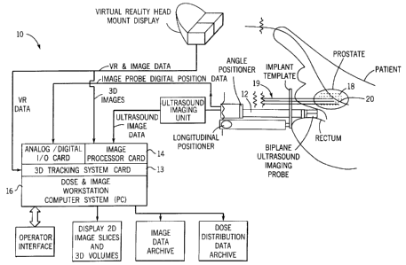
A system 10 constructed in accordance with an example of the invention is
illustrated generally in FIG. 1. A three-dimensional probe 12 accumulates
image
data from a treatment region or organ of a patient, image data is processed
using
a three-dimensional imaging card 14. The probe 12 preferably is an ultrasound
device but can be any other rapid imaging technology, such as rapid CT or MR.
A
conventional personal computer 16 having a monitor can be used to operate on
the
image data from the imaging card 14 using conventional software and hardware
tools to be described in more detail hereinafter. Radioactive seeds 18 are
provided
for insertion using any one of a variety of conventional means for inserting
devices
or articles into the human body, such as insertion devices 19, which may be
either
needles or stiff catheters. The three-dimensional ultrasound probe 12,
therefore,
provides an image signal to the computer 16 and a virtual reality interface
card 13
coupled to the imaging card 14 which enables a user to visualize a translucent
image of the patient organ and real time interaction of any one of a variety
of
treatment devices, such as the implant needles 19 or a Foley catheter 20, and
one
of the seeds 18 within the organ. Computer software can be utilized in a
conventional manner to visualize the three-dimensional imaging data in various
formats (see Appendix and discussion hereinafter). The formats include
orthogonal
two dimensional images, oblique two-dimensional images, and translucent three-
-6-
CA 02333583 2004-11-24
dimensional rendering. All of these reconstructions can be directly displayed
on the
computer monitor; and three-dimensional translucent, stereoscopic, rendering
is also
available in the VR (Virtual Reality) mode.
One of the preferred ultrasound probe 12 for example, is a conventional
Kretz ultrasound imaging system manufactured by Kretz Corporation, now
available
as Medison Combison 530 through Medison America Corporation, Pleasantown,
Calif. This system and other such conventional systems are readily available
and
can provide real time ultrasound image data. The Medison Combison ultrasound
system incorporates an endorectal probe which acquires multiple image planes
in
real time and in certain embodiments the software (see Appendix) reconstructs
the
translucent three-dimensional volume. Another example is of a B&K Leopard
ultrasound imaging system with endorectal imaging probe (Boston, Mass.).
Alternate systems include biplanar two-dimensional imaging systems with the
probe
mounted in a stepper motor driven holder for rapid automatic acquisition of
multiple image planes.
In a most preferred form of the invention, the system 10 includes computer
software for real-time image acquisition, image contouring, dose calculation
and
display software, dose volume histograms, three-dimensional dose contours,
post-
implant seed localization, and the patient scheduling spreadsheet software.
Attached
is an Appendix of computer software used to implement these functionalities.
FIGS.
12A to 12M illustrate the operative connection between modules of the
software.
The system software enables a two-dimensional and three-dimensional image
visualization for brachytherapy employing two-dimensional ultrasound imaging
for
use in radioactive seed implants of the prostate. The software for the
brachytherapy
seed implant and dose calculation system was developed on a Pentium-based
processor with supporting graphics and digitizing hardware. The software
consists
of two-dimensional and three-dimensional routines. The two-dimensional tools
consist of standard imaging tools largely available for CT and MRI
applications.
These tools include displays of the imaging volume in any of the three
standard
orthogonal planes (transverse, sagittal, and coronal), in addition to the
ability to
display the imaging in any arbitrary, oblique imaging plane. Standard image
processing tools such as real time window leveling, zoom and pan will be
_7_
CA 02333583 2000-11-27
WO 99/60921 PCT/US99/11847
available. The three-dimensional tools consist of a three-dimensional
rendering of
the actual contour slices imaging data. Based upon volumetric patient studies,
the
prostate volume can be displayed. The user has the option of viewing one or a
mixture of two-dimensional and three-dimensional surface views on the monitor.
Contouring tools are also available for the user to draw with the mouse
outlines, or contours, of any structure visible on the imaging plane. Each
contour
can be varied as to color, line thickness, and line pattern to aid in
distinguishing
between different contour sets.
Once a set of two-dimensional contours has been defined. either manually or
automatically, on a number of different image slices they can be reconstructed
in
real time in the three-dimensional translucent view (described in more detail
hereinafter). This results in a surface rendering of the volume bounded by the
contours. The surface rendering can be chosen to be transparent, solid, or
invisible
(not rendered at all).
Once a seed has been placed into treatment position (details concerning seed
implantation provided later), the user has the ability to display the dose of
one or a
set of seeds. The dose as a function of position for a cylindrical '25 or
'°3 Pd seed of
a given activity can be determined from a lookup table or calculated from an
analytic formula. The dose field can be visualized as a set of isodose lines
in two-
dimensions or isodose surface in three-dimensions. The process of constructing
an
isodose line or surface is defined by simply drawing a point for each pixel
voxel
which contains a certain specified dose value. For example, the user can
specify
that the 137 Gv. 120 <~y, 100 Gy, and 60 Gy isodose lines be drawn on the two-
dimensional slice for each image plane, and the 137 Gy isodose surface shown
on
the three-dimensional rendered mode. Again, similar to the contoured volumes,
the
isodose surface can be reconstructed in any of the user selected modes defined
for
contoured volumes.
The features/capabilities of the system software functionalities include:
complete patient database archive and dose plan "playback" ; external image
import
capability; look-up taL~les for multiple seed kits and template guides;
multiple
ultrasound imaging machine configuration capability; image slice contourin6
using
-g_
CA 02333583 2000-11-27
WO 99/64921 PCT/US99/11847
mouse, with edit capability; image cropping, image sizing, tiling, cascading;
three-
dimensional display of prostate, urethra, and other anatomies; rapid "on-line"
dose
calculation in operating room/cysto suite during procedure; dose display with
isodose lines, three-dimensional translucent, and dithered isodoses; image
export
and printing {dose slices, contour slices, etc. ); seed implant plan export
and
printing; dose volume histograms (with export and printing); three-dimensional
image support including three-dimensional image reconstruction from slices;
three-
dimensional display of isodose surfaces; image slice selection from three-
dimensional image through any transverse plane; post-implant assessment
including
automatic seed localization; computer-controlled stepper; selection of manual
(mouse entry), semi-automatic (button push), or full automatic (computer-
controlled
stepper) ultrasound image collection.
For collecting ultrasound image data, the diagnostic transrectal ultrasound
probe 12 (see FIG. 2) is inserted into the patient's rectum to obtain real
time
volumetric images of the prostate for use during the implant procedure. The
diagnostic probe 12 is preferably a phased array probe designed so that the
array of
transducers can rotate about the axis of the array sweeping out a three-
dimensional
imaging volume. As the probe 12 rotates, images are captured and digitized by
use of
the imaging card 14 (see FIG. 1), so as to create a fixed number of images
slices per
rotation. An alternative method utilizes a transverse oriented phased array
form of the
endorectal probe 12 which is moved longitudinally in an automated rapid
seauence sc~
as to create a series of transverse image slices automatically. Another
embodiment of
the probe 12 can incorporate multiple transverse phased arrays (shown in
phantom in
FIG. 1B) arranged parallel to each other orthogonal to the axis of an
endorectal probe
to produce multiple simultaneous image slices (see. for example, FIGS. SA and
SB).
The three-dimensional image data will be represented as a three dimensional
image
raster.
The ultrasound probe 12 can be mounted into a probe holder 30 (see FIGS. 3A
and 3C) with FIG. 3B illustrating one example of an ultrasound image from an
anatomical prostate phantom employed to carry out testing and platlning. The
probe
holder 30 includes a digital encoder 42 for providing information regarding
the
_y_
CA 02333583 2000-11-27
WO 99/60921 PCT/US99111847
position of all of the desired ultrasound image planes in the prostate
relative to each
other. The image plane location will be automatically sent to the system
computer and
"tagged" to the acquired ultrasound image for that position (FIG. 2). Thus, it
will be
possible to reproduce the longitudinal and lateral positions of the implant
catheters for
the ultrasound therapy applicators and for the temperature probes.
A probe holder/stepper assembly 21 (see FIG. lA and in particular FIG. 131
accommodates most ultrasound endorectal probes from various manufacturers. A
"collett" 23 surrounds the probe 12 and is inserted into the stepper / probe
holder
assembly 21. The stepper 21 is a digital device with an automatic imaging link
to
the ultrasound machine and to the remainder of the system 10. The stepper 21
has
three digitailv encoded axes: main probe stage longitudinal axis 31, needle
insertion template longitudinal axis 33, and the rotational axis 35 of the
imaging
probe itself. The stepper 21 automatically records the longitudinal (z-axis)
position
and sends that information to the computer 16. Whenever the user desires to
acquire an image plane, the spatial position of that image plane is
automatically
registered with that image. Thus, it requires less than a minute to digitally
acquire
and document all the image planes in a typical volume study. The stepper 21
can be
incrementally moved by the user with stepper knob 34 and the template 25 can
be
stepped by template positioning control 37.
The holder/stepper assembly 21 can move the probe 12 in 2.5 rrvn
increments. A transrectal probe from B&K was used which operates at a
frequenc_.
of 7.5 MHz and contains two sets of 128 transducer elements forming both
transverse and sagittal imaging assays. The imaging probe 12 was moved via a
knob on the side of the stepper 21 and its position measured via a digitally
interfaced optical position encoder. The probe holder/stepper 21 with
transrectal
probe 12 mounted is shown in FIG. 1. The real time mufti-plane ultrasound
probe
12 was modeled by obtaining single digitized transverse images at either 2.5
or 5
mm intervals through the ultrasound prostate imaging phantom. The ultrasound
prostate phantom is available from Computerized Imaging Reference Systems Inc.
and contains a model of a prostate, urethra, and seminal vesicles immersed in
a gel
filled plastic box. The box has a cylindrical hole in the base for the
insertion and
-10-
CA 02333583 2000-11-27
WO 99/60921 PCT/US99/11847
positioning of the transrectal probe and a perineal membrane for performing
practice brachytherapy implants. FIGS. 4A anc! 4B display a schematic of the
brachytherapy phantom. Unce the static image slices have been digitized they
were
then inputted to the software in a continuous cycle to model actual real time
acquisition of a full volume. Multiple sets of image slices can be obtained
and
randomly cycled to more accurately simulate the actual three-dimensional real
time
ultrasound probe 12. The image slices are input to the software transparently.
A probe stabilization system 27 (see FIG. 13B) is designed for use with any
standard probe holder/stepper 21, yet it is optimized for use as part of the
system
10. This stabilization system 27 attaches easily and quickly to the cysto or
operating room table using clamps 28, yet provides maximum flexibility during
patient setup. The stabilization system 27 provides for five degrees of
freedom of
motion, yet is robust and stable. The probe stabilization system 27 includes a
stepper probe stand control 28 which allows up and down movement. Further
motion control is provided by stabilizer control 29 which enables up and down
motion and left to right along rods 30 (horizontal) and rods 31 (vertical}.
Gross
motions are positively controlled in a stable manner. Fine motions are
obtained
with the same controls and are exactly reproducible.
A variety of the templates 25 (see FIG. 1) for the needles 19 can be used
with the system 10. All of these implant templates are disposable preferably.
The
system 10 can also accommodate use of other standard templates 25. The system
software (see Appendix) can store the configuration of any number of the
templates
25 for immediate recall. Each template 25 stored in the system 10 is spatially
registered with each ultrasound system configuration stored in the system
software.
The system templates 25 provide assurance of sterility for patient contact at
a cost similar to that of sterilization of the usual standard templates. The
disposable
system templates 25 are a fraction of the cost of standard reusable templates
and
provide greater safety.
There are several possible image processing cards which could be utilized;
however, using current modalities each of the processing cards is configured
specifically for three-dimensional. The three-dimensional image raster is
buffered;
-11-
CA 02333583 2000-11-27
WO 99!60921 PCT/US99/11847
and thus, for example, if the two-dimensional images are 512x5I2 and there are
sixteen image planes in the probe 12, and each pixel is a byte (256 gray
scales), at
least a 512x512x16 byte = 4.? Mbyte image buffer in the card 14 is needed.
Several
commercial cards (for example, made by Coreco, Matrox and Integral
Technologies)
can be equipped with this amount of video RAM (VRAM), but the way the card's
hardware interacts with the computer's video and software drivers does not
utilize this
data in three-dimensional. Current available methodologies enable augmenting
the
software and some hardware of these cards so that they can act as a three-
dimensional
card. The processing and memory architecture preferably is designed to allow
for
simultaneous image acquisition and processing. The digitizing card should also
preferably have standard imaging tools, such as real time window and leveling,
zoom
and pan of the ultrasound images. Some existing cards (e.g., Matrox; Coreco)
do
provide standard imaging tools.
The three-dimensional image data arising from the ultrasound probe 12 is
preferably buffered on the imaging card 14. The three-dimensional image is
preferably represented as a series of two-dimensional images. This is referred
to as
the image stack or three-dimensional image raster. The three-dimensional image
raster is represented in memory as a linear array of bytes of length NxMxP
where N is
the width of the two-dimensional image in pixels, M is the height a two-
dimensional
image in pixels, and P is the number of two-dimensional images in the image
stack.
In a preferred embodiment the user can include defined formats. Entire three-
dimensional image stacks at specific times during the intraoperative session
can be
stored in the DICOM standard. T'he user will have the ability to select a
three-
dimensional image volume for archiving as part of the system software. These
image
stacks can then be reviewed in any of the various visualization modes
(standard
orthogonal two-dimensional views, oblique two-dimensional views, or three-
dimensional translucent views) as described above. In addition, the user will
have the
ability to store any of the two-dimensional views available at any time during
the
intraoperative session.
The computational platform can, for example, be any form of computing
means, such as the personal computer 16, which incorporates a PCI bus
architecture.
-12-
CA 02333583 2000-11-27
WO 99/60921 PCT/US99/11847
Currently, PCI bus is preferable over the ISA or EISA bus because the PCI bus
is
much faster. However, a generic system which will be suitable for this
applicable will
be described. A 200 MHz (or greater speed) Pc:ntium/Pentium-Pro computer
supplied
with 128 Mbytes of RAM and a 6.0 Gbyte hard disk should be sufficient RAM and
disk memory to run the software in a real-time fashion and to archive all
patient data.
There should be sufficient RAM to facilitate host image processing in parallel
with
onboard image processing for quality assurance checks. A high resolution
monitor
capable of displaying at least 1280x 1024x64 bit resolutions is preferably
used.
Based on currently available technology., the ultrasound images obtained from
the ultrasound imaging system of the ultrasound probe 12 can be of good
diagnostic
quality. When transforming this input image data into a three-dimensional
representation, whether in the three-dimensional perspective mode or the real
time VR
mode, the resultant volumes can, however, be noisy and hinder diagnostic and
spatial
accuracy. In order to improve the image quality, a number of conventional
hardware
and software filters can be used which will filter the incoming image data
stored on the
imaging card 14. Routines such as image pixel averaging, smoothing, and
interpolation can improve the three-dimensional rendering of the imaging
volume.
These sets of filters or routines are to be distinguished from the set of
standard
imaging tools running on the host C.'fU which are available within a
conventional
imaging software package.
In the preferred embodiment, three of the perspective views are the standaru
transverse, coronal and sagittal two-dimensional views. These three orthogonal
views
are taken from a user specified location within the imaging space. For
example, the
user can request that the three orthogonal views have their common centers at
a spatial
position of (5.0 cm, 15.0, 25.0 cm) relative to the origin of the template
system. One
also can select the reference point of either of the three orthogonal views
independently, that is the three views do not have to have common center
points. As
mentioned hereinbefore, FIGS. 5A and 5B show examples of several example two-
dimensional views from a three-dimensional ultrasound image volume. FIG. 6
shows
a number of possible viewing directions, and FI:G. 7 gives further examples of
translucent three-dimensional viewing from different angles. The three-
dimensional
-1J-
CA 02333583 2000-11-27
WO 99/60921 PCT/US99/118a7
ultrasound image volume was obtained from actual ultrasound images of a human
prostate and of a prostate implant phantom.
On each of the views, one can define, draw and edit contours using
conventional computer software, such as Microsoft Foundation Class (MFC) view
files. Each contour can be given a unique name by the user, and then drawn by
the
user using the mouse of the computer 16. All attributes of the contours such
as name
and color can, based on conventional imaging software, be user selectable. The
user
can also edit the contours by selecting functions, such as adding a point to a
contour,
deleting a point from a contour or deleting the entire contour. Once the
contours are
defined, the user has the option to render them in three-dimensional or view
in
conventional two-dimensional mode on the three-dimensional perspective mode or
viewed in the VR modes. Again. all contour three-dimensional attributes such
as color.
lighting, and shading are user controlled. The contours by default appear on
the tv~o-
dimensional images, however, the user can control the individual contour's two-
dimensional and three-dimensional visibility.
In order to improve the ability to visualise the real time, three-dimensional
information, the three-dimensional image raster can be rendered as a real
time,
transparent, three-dimensional volume. This transparent volume can be viewed
and
displayed on the monitor of the computer 16 at any arbitrary viewing angle and
is
calculated using conventional three-dimensional object reconstruction
algorithms.
Such standard algorithms can render a large imaging volume in fractions of a
second.
even on present day computing platforms. The transparent nature of the
reconstruction thus allows the user to "see" inside any objects which appear
in the
imaging volume. For example, if the prostate is imaged in the imaging volume,
then
it will be reconstructed as a transparent volume, in which other anatomical
landmarks
such as the urethra, tissue abnormalities or calcifications can be seen. In
addition, if
any other objects such as needles or catheters arf: inserted into the
prostate, and if they
are visible in the ultrasound images, they will be seen as they enter the
prostate (see
FIG. 8 showing introduction of the seed 18 with the catheter/needle 19). Since
the
volumes are rendered as transparent solids, the needles 19 (and other
articles) can thus
easily be seen as they trove inside the prostate volume as well. Since the
ultrasound
-14-
CA 02333583 2000-11-27
WO 99/60921 PCT/(JS99/11847
images are obtained in real time, the three-dimensional perspective
reconstruction is
also rendered in real time. The preferred algorithm for the perspective three-
dimensional reconstruction is the known Bresenham ray-trace algorithm.
As described above, in the routine process of brachytherapy planning, the
patient undergoes an initial volumetric ultrasound scan using the probe 12.
This scan
is done before the radiation therapy planning or the actual implant. During
the
radiation therapy planning, the ideal positions of the radioactive seeds 18
(see FIG. 1)
within the prostate are determined. This ideal seed distribution is optimized
to deliver
a dose distribution within the prostate that will deliver all the radiation
dose to the
target volume only, while sparing the surrounding healthy tissues such as the
rectum
and bladder. The optimal positions of the seeds 18 and the optimal position of
the
needles 19 are recorded for later use in the operating room when the needles
19 are
loaded into the patient. The seeds 18 are then loaded into the needles 19, and
the
physician then attempts to place the needles 19 inside the prostate using a
template 25
according to the treatment dose plan positions (again, see example in FIG.
8)..
In the most preferred embodiment the seeds 18 are loaded through the needles
19. A selection of different types of the seeds 18 (different levels of
radioactivity) can
be loaded through passageways, P, shown in FI(l. 14. Optical sensors 90 and 91
are
redundantly disposed adjacent each of the passageways P with an associated
microprocessor 93 and 97 monitoring the number of the seeds 18 being instilled
through the needle 19. Radiation sensors 96 and 98 monitor the radiation
activity of
the seeds 18 being loaded into the needle 19. Spacers 100 are also instilled
into the
needle 19 for separating the seeds 18 to achieve the desired level of
radiation activity
and radiation contours. Optical sensors 92 sense, redundantly as for the seeds
18, the
passage of the spacers 100.
In a most preferred form of the invention, an automatic seed/needle loading
method is implemented automatically loading implant needles 19 with the
radiation
seeds 18 and spacers 29 based upon a pre-plan (dose plan) determined in the
operating room (OR). 'This method accommodates the spacers 29 and separate
leaded-acrylic see-through "bins" for the seeds 18 of two different activity
levels.
Thus, the needles 19 can be auto-loaded based upon optimal dose plans
requiring
-15-
CA 02333583 2000-11-27
WO 99/60921 PCT/US99/11847
seeds of different activity levels. The automatic seed/needle loading method
and
system interfaces directly to the computer 16 an<i reads the dose plan
information
using the software of the Appendix. A display on the auto-loader then displays
to
the operator each needle number, template coordinate location, and status of
needle
loading. Each of the needles 19 are attached one at a time to the auto-loader
assembly with a standard leer lock. 'The auto-loader has a sensor at the
needle
attachment point which detects if the needle 19 is attached for loading. Each
of the
needles 19 are then loaded in accordance with the pre-plan.
The automatic seed/needle loading method and system is therefore
completely double-redundant, as mentioned hereinbefore. It incorporates the
use of
two totally independent microprocessors 93 and 94 which constantly check each
other. Both the microprocessors 93 and 94 are also in communication with the
system computer 16. The seeds 18 and the spacers 29 are optically counted
independently. Needle loading is optically checked for total number of loaded
items
and, further, a radiation detector array scans each needles 19 to confirm that
the
seed/spacer loading radiation pattern matches the pre-plan. This automatic
method
and system will do so in the operating room in minimal time, without the risk
of
human error in the loading of needles. The seed loading method will include a
pair
of redundant 8051 microcontrollers (the microprocessors 93 and 94) which will
be
interfaced to the dose-planning and implant system computer 16 via a serial
port.
This interface will read the dose pre-plan information from the computer 16.
without the need for paper printouts and manual loading. That information will
be
transferred to a controller which controls the loading of each needle 19. T'he
requirements and design criteria for the automatic seed-needle loading method
and
system are described as Follows: self-contained and capable of loading seeds
and
spacers; system will protect operator of system from radiation; dual redundant
counting of seeds and spacers; dual redundant radiation detectors for
measuring
radiation from active seeds versus spacers; dual redundant measurement of
radiation
seed positions in needles; system check for failure of either or both
redundant
counting and measurement systems; alarm to both operator and to dose-planning
and implant computer system in the event of error; ongoing account of seed and
-16-
CA 02333583 2000-11-27
WO 99/60921 PCT/LJS99/11847
spacer inventory; tracks needle loading configuration and displays to operator
the
designated template grid hole coordinates for each needle loaded; sterilized
cassettes
for holding seeds and spacers, plus sterilizable needle connector; includes
one
cassette for seeds and one cassette for spacers; dispenses one seed and one
spacer at
a time, and verifies optically and by radiation detector; system displays
needle
number and template grid location during loading procedure; automatic
acquisition
of needle loading plan from main system computer; serial interface with
handshake
protocol and verification; self-contained (mechanical, power, logic,
microcontrollers); operates only if connected to main system computer.
A convenient storage system for the needles 113 can be loaded by the
automatic seed/needle loading method system. The face of this unit has a hole
grid
pattern which matches tile implant template 25. Loaded needles may be inserted
into this unit until they are used. The entire unit is shielded for radiation
leakage
minimization. The template-like face of the unit is available in both a
reusable,
sterilizable version and disposable versions which match all standard implant
template faces. Faces of the unit detach easily and quickly for sterilization
or
disposal.
The dose as a function of position for a cylindrical "~I seed of a given
activity
can be determined from a lookup table or calculated from a conventional
analytic
formula. The dose field can be visualized as a set of isodose lines in two-
dimensional
or isodose surface in three-dimensional. The dose computation routine is based
upon
the TG43 standard adopted by the AAPM (American Association of Physicists in
Medicine) entitled "Dosimetry of Interstitial Brach~~therapy Sources":
Recommendations of the AAPM Radiation Therapy Committee Task Group No. 43
which specifies the dose model and the data used in the dose calculation. This
particular implementation runs extremely fast on a conventional 233MHz PC,,
computing the dose for a single seed in less than 0.~ seconds. The total three-
dimensional dose distribution within the prostate for a 100 seed implant
requires only
50 seconds, or less than one minute total computation time. Thus, this can be
done
"on line" in the operating; room.
_l7_
CA 02333583 2000-11-27
WO 99/60921 PCT/US99/11847
In the two-dimensional, three-dimensional perspective, or the real time VR
modes, the user has the ability to view the optimized seeds 18 and the needles
19 in
the same volume as the real time ultrasound data. This allows the physician to
see
exactly where the needles 19 should go and hence make adjustments to position
the
needles 19 optimally. The pre-planned, optimal positioned needles 19 and the
seeds
18 can be rendered again as a transparent solid, the color of which is user
selectable.
As the real needles 19 are inserted into the prostate, their positions
relative to the ideal
needle placements based on the dose plan can be monitored in real time. Any
deviation of the position of a given needles 19 can be quickly and accurately
readjusted
so as to follow the path of the ideal needles 19. As the different needles 19
are placed
at different positions inside the prostate, the viewing angle can be adjusted
to facilitate
viewing of the needle or catheter placement. FIGS. ~A and SB displays
perspective
three-dimensional views and the three orthogonal reconstructions of the image
data
along with the pre-planned catheter positions. The pre-planned needles 19 can
also be
viewed in the VR mode as virtual objects overlaid onto the imaging volume.
A flowchart description of the translucent volume visualization methodology is
shown in FIG. 10. The input image volume is described by the vectors i, j, k
of
appropriate magnitude for the volume. The viewing angle parameters are the
angles
0, ~ described on FIG. ti and FIG. 10. 'the rotation matrix, R, is calculated
using the
formulae given in the flowchart of FIG. 10. The entire imaging volume is
calculated
by multiplying the rotation matrices in the x, y, z directions by the
respective vectors
i, j and k describing the incremental portions along the x, y, z directions.
Thus, the
multiplying vector is (i-i~, j j", k-k~) where i", j~, k~ are the starting
points along x, y
and z axes and the volume is determined by summing the component contributions
shown in FIG. 10. The three-dimensional translucent image is then created by
computing the translucent two-dimensional image over the entire image volume
and
summing the z-pixels.
A virtual reality interface system can be composed of a conventional head
mounted display (HMD) 50 shown in FIG. 11 and a 6D (x,y,z, roll, pitch, yaw)
tracking system. The HMD 50 consists of two color monitors which mount to a
head
set in the position directly in front of the eyes. The HMD 50 is based on the
principal
-18-
CA 02333583 2000-11-27
WO 99/60921 PCT/US99/11847
that whatever is displayed on each monitor is directly incident on the retina
for each
eye, and hence true three-dimensional images can be created by rendering
objects as
three-dimensional perspective images for each eye. Given the distance between
the
eyes (the interocular distance which is approximately 80 mm) and the distance
and
spherical angles of the distance of the center line between the eyes from the
coordinate
origin, the two-dimensional images which appear in each of the two monitors
can be
determined exactly as described above. This results in a true three-
dimensional image
as perceived by the user. Therefore, as the user moves his or her head or
moves
around the room, the distance from the origin and the spherical angles also
change.
This motion of the user or user's head can be obtained from the VR tracking
system.
Given these spatial parameters, the images which are reconstructed in the two
eye
monitors can be updated in real time, giving the user the illusion of the
object really
existing in three-dimensional space. The user literally has the ability to
walk around
the object, viewing it in three-dimensional space.
Instead of reconstructing computer generated geometric objects as is usually
the case in VR, the transparent, three-dimensional reconstruction of the real
time
imaging data will preferably be reconstructed. Hence as the physician walks
around
the patient undergoing the implant, the physician will see the three-
dimensional
ultrasound volume mapped inside the patient's pelvis, spatially correlated to
the
position of the patient's real prostate (or other organ) and anatomy. The
physician can
"see" inside the patient to the extent of what is visible in the ultrasound
imaging
volume. Since the ultrasound probe 12 is locked down to the template, which is
then
secured to the floor, the exact positions of all vox.els in the ultrasound
imaging volume
are known exactly relative to the template, and hence relative to the room.
As the needles 19 are inserted into the patient, they will appear in the image
volume and hence are reconstructed in the VR reconstruction. All of this
occurs in
real time so that the physician also can see the needles 19 enter the prostate
in real
time. As mentioned above, if the pre-planned, optimized needles 19 are
displayed, the
physician can then see the position of the actual needles 19 as they are being
inserted
relative to the optimal placement. Hence, the physician has the ability to
adjust the
needles 19 to correspond to their optimal positions. In addition, since the
needles 19
-19-
CA 02333583 2000-11-27
WO 99/60921 PCT/US99/11847
are automatically extracted, the computer software has the ability to
calculate and
render the three-dimensional dose distribution in real time as the needles 19
are being
inserted .
As an example, a currently available, a fast and inexpensive HMD is made by
Virtual-IO Corporation (Mountain View, CA). T'he HMD is full color with two
0.70
LCD displays with a resolution of 180,000 pixels per LCD panel. The video
input is
NTSC with field sequential format. The LCD panels are semitransparent,
allowing
the real outside world to be included in the virtual reconstruction. The field
of view is
30° for each eye. A six degree of freedom (6 DOF) tracking system can
also be
attached to the HMD. The 6 DOF tracking system allows for the determination of
the
spatial position of the user's head and the yaw, pitch, and roll of the head.
The
conventional head set weighs only 8 ounces and comes with stereo sound. Stereo
sound is an extremely valuable technology in the operating room. With this
capability, the physician has the ability to monitor the patient's heart rate
and
respiration rate while performing the implant. Hence any fluctuation in the
patient's
vital signs can be instantly accessed and acted thereon if necessary.
The radioactive seeds 18 are made of high density material such as stainless
steel, and hence have a very bright response in the ultrasound images.
Therefore,
automatic seed detection in the ultrasound images can readily be accomplished,
for
example, by a simple thresholding algorithm along with the requirement that
the
resultant objects which are removed by threshold have a certain maximum size
determined by the actual size of the seeds.
Near-real-time visualization will provide immediate feedback to the physician
during the implant process itself. There is a clear need for the visualization
being
available during the implant process. The nearly real time visualization is of
great
importance to the effective use of a translucent overlay of the ideal seed pre-
plan (from
the therapy planning process) in the three-dimensional volume. The physician
can
"see" in nearly real time the relationship of the needles and seeds being
implanted to
the ideal pre-plan locations and quickly accommodate redirection required
prior to
leaving the radiation seeds. Further, the need for this in three-dimensional
representation is very important to overcome the greatest fundamental
limitation in
-20-
CA 02333583 2000-11-27
WO 99/60921 PCT/US99/11847
brachytherapy, which is knowing at the same time both the lateral placement
and
longitudinal placement of needles and seeds relative to the target volume and
pre-plan.
This is a three-dimensional problem which has up until now been addressed in
two-
dimensional in a stepwise fashion without the ability to "see" the exact
location of
where you are in the target. This real time three-dimensional visualization
also would
speed the implant process in the case of brachytherapy as well as make it more
accurate. It would also speed other minimally invasive surgical procedures and
localized tissue ablation procedures (for example, cryosurgery or localized
selected
ablation of diseased liver tissue or local removal of breast tissue). These
procedures
could be accomplished with real time visualization inside the tissue being
treated with
greater accuracy in shorter time. This aspect would reduce operating room time
and
costs to the patient and health care system.
While preferred embodiments of the inventions have been shown and
described, it will be clear to those skilled in the art that various changes
and
modifications can be made without departing from the invention in its broader
aspects
as set forth in the claims provided hereinafter.
-21-