Language selection

Search

Patent 2333827 Summary

Third-party information liability

Some of the information on this Web page has been provided by external sources. The Government of Canada is not responsible for the accuracy, reliability or currency of the information supplied by external sources. Users wishing to rely upon this information should consult directly with the source of the information. Content provided by external sources is not subject to official languages, privacy and accessibility requirements.

Claims and Abstract availability

Any discrepancies in the text and image of the Claims and Abstract are due to differing posting times. Text of the Claims and Abstract are posted:

  • At the time the application is open to public inspection;
  • At the time of issue of the patent (grant).
(12) Patent Application: (11) CA 2333827
(54) English Title: SHOWER ARM MOUNTING
(54) French Title: SUPPORT DE BRAS DE DOUCHE
Status: Deemed Abandoned and Beyond the Period of Reinstatement - Pending Response to Notice of Disregarded Communication
Bibliographic Data
(51) International Patent Classification (IPC):
  • B05B 15/60 (2018.01)
  • A47K 03/28 (2006.01)
  • E03C 01/042 (2006.01)
(72) Inventors :
  • BERTRAND, JOHN E. (United States of America)
  • BRATTOLI, MICHAEL A. (United States of America)
(73) Owners :
  • MOEN INCORPORATED
(71) Applicants :
  • MOEN INCORPORATED (United States of America)
(74) Agent: NORTON ROSE FULBRIGHT CANADA LLP/S.E.N.C.R.L., S.R.L.
(74) Associate agent:
(45) Issued:
(22) Filed Date: 2001-02-05
(41) Open to Public Inspection: 2001-08-15
Availability of licence: N/A
Dedicated to the Public: N/A
(25) Language of filing: English

Patent Cooperation Treaty (PCT): No

(30) Application Priority Data:
Application No. Country/Territory Date
09/500,945 (United States of America) 2000-02-15

Abstracts

English Abstract


A modular shower arm assembly for use in removably attaching a shower
fixture to the unthreaded end of a pipe extending outwardly from a shower
stall wall without
affecting connection of the pipe to a water supply system behind the shower
wall uses an
adapter sleeve closely fitting over the pipe and located within a chamber in
the shower arm
water passage. There is a threaded fastener which extends from the top or
upper surface of the
shower arm, where it is normally unseen, to mount the sleeve and the shower
arm to the pipe.


Claims

Note: Claims are shown in the official language in which they were submitted.

The embodiments of the invention in which an exclusive property or privilege
is
claimed are defined as follows:
1. A modular shower arm assembly for use in removably attaching a shower
fixture to an unthreaded end of a pipe extending outwardly from a shower wall
without
affecting connection of the pipe to a water supply system behind the shower
wall, said shower
arm assembly including:
a tubular shower arm adapted on one end thereof to mount a shower fixture, an
adapter sleeve having an internal diameter providing a close, but sliding, fit
on said pipe;
said tubular shower arm having an internal water passage which includes a
chamber sized to closely fit about the adapter sleeve exterior diameter and to
locate the sleeve
positively relative to the shower arm;
a seal member located within said passage adjacent said adapter sleeve and in
sealing contact with said passage and said pipe; and
a fastener extending through aligned openings in said adapter sleeve and an
upper exterior surface of said tubular shower arm to fix said shower arm and
sleeve to said
pipe.
2. The modular shower arm assembly of claim 1 wherein said water passage
chamber has an interior circumferential cylindrical wall and an adjacent
radial wall, defining
an end of said chamber, with said adapter sleeve being sized to fit against
both said
circumferential cylindrical wall and said radial wall when positioned within
said chamber.
6

3. The modular shower arm assembly of claim 2 wherein said tubular shower
arm opening is threaded and said fastener has an exterior thread.
4. The modular shower arm assembly of claim 3 wherein the opening in said
adapter sleeve, in alignment with said shower arm opening, is an arcuate slot.
5. The modular shower arm assembly of claim 4 wherein said shower arm
water passage has a second chamber, directly adjacent the chamber for said
adapter sleeve,
with said seal ring being positioned within said second chamber, and said
second chamber
being downstream of said sleeve chamber.
7

Description

Note: Descriptions are shown in the official language in which they were submitted.


CA 02333827 2001-02-05
SHOWER ARM MOUNTING
THE FIELD OF THE INVENTION
The present invention relates to a modular shower arm construction in which
the
visible, exterior and/or decorative elements of a shower installation may be
removed without
affecting or disturbing the connection between the pipe which extends through
the shower stall
wall and the water supply. It is conventional in shower and bath installations
for there to be a
pipe which connects to the water supply and extends outwardly through the
shower stall wall.
This pipe is often threaded and a shower fixture is threaded onto the pipe.
Most homeowners
are reluctant to remove an existing shower fixture from the wall because of
fear that in so
doing they would break the connection between the pipe and the interior water
supply
connection which is behind the shower wall.
The present invention provides a mounting system for a shower fixture, such as
a shower head, in which the decorative and exposed elements of the shower
assembly,
specifically the shower head, the shower arm and escutcheon if one is present,
may be
removed and replaced with elements of a different esthetic appearance without
in any way
affecting the behind-the-wall connection with the water supply. There is a
pipe which extends
outwardly through the shower stall wall from the water supply and this pipe
may have a
smooth, unthreaded end. A tubular shower arm, decorative in outer appearance,
is mounted to
the pipe through the use of an adapter sleeve. A set screw, which extends
through aligned
openings in the tubular shower arm and adapter sleeve, but is normally not
visible to a user of
the shower fixture, fixes the tubular shower arm and adapter sleeve on the
unthreaded end of
the pipe. The shower fixture is mounted to the exposed end of the tubular
shower arm and the

CA 02333827 2001-02-05
shower arm masks or covers the connection to the pipe extending outwardly from
the shower
stall wall.
SUMMARY OF THE INVENTION
The present invention relates to a modular shower arm assembly and more
specifically to an assembly in which its decorative appearance may be changed
and the
elements of the assembly replaced without affecting the connection between the
water supply
and the pipe which extends outwardly through the shower stall wall.
Another purpose is to provide a reliable, simply constructed, shower assembly
mounting system which provides for removal and replacement of the decorative
elements
associated with a shower fixture, without removing or affecting the tubular
water conduit that
extends outwardly from the shower stall wall.
Another purpose is a shower arm construction as described in which all
decorative elements may be replaced from in front of the shower stall wall.
Another purpose is a modular shower arm assembly as described in which the
attachment of the shower decorative elements to the shower stall wall pipe are
normally hidden
from view.
Other purposes will appear in the ensuing specification, drawings and claims.
BRIEF DESCRIPTION OF THE DRAWINGS
The invention is illustrated diagrammatically in the following drawings
wherein:
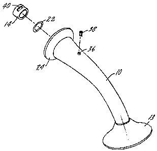
Fig. 1 is an exploded perspective of the modular shower arm assembly of the
present invention; and
Fig. 2 is an axial section through the shower arm assembly of Fig. 1.
2

CA 02333827 2001-02-05
DESCRIPTION OF THE PREFERRED EMBODIMENT
The present invention relates to a mounting system for shower fixtures, such
as
shower heads, but it can also have application to the mounting of bathtub
spouts. More
specifically, the invention pertains to a mounting system in which the
visible, normally
decorative, elements of a shower fixture installation may be removed and
replaced in
connection with changing the decor of a bathroom or lavatory without affecting
the water
supply pipe connection which is normally located behind the shower stall wall.
Most homeowners are reluctant to remove an existing shower fixture, as this
usually dictates that the connecting pipe must be unscrewed from a fitting
behind the shower
wall. Homeowners usually prefer that this function be performed by a licensed
plumber. The
present invention provides a mounting system in which all of the decorative
components may
be replaced without in any way altering or removing the water supply pipe
which protrudes
through the shower stall wall and is connected to the water supply system
behind the wall.
The components of the mounting system are all positioned on the water supply
pipe in a
manner in which they may be simply and easily removed with normal hand tools.
The
components which provide the connection between the shower fixture and the
pipe are
normally hidden from view with the exception of a set screw which extends down
through the
top of the tubular shower arm through an opening which is normally not visible
from someone
using the shower fixture. The components forming the connection slide over the
conventional
copper pipe or "stubout" which extends through the shower stall wall.
In Fig. 1 the components forming the shower fixture installation include a
tubular shower arm 10 having an exterior decorative appearance and a threaded
end 12 for the
3

CA 02333827 2001-02-05
mounting of a shower fixture such as a shower head 13. There is an adapter
sleeve 14 which
will form a portion of the connection between the tubular shower arm and the
copper pipe 16
which extends through the front face 18 of the wall 20 of the shower stall.
There is a seal ring
22 which will prevent water flowing through the tubular shower arm to the
shower fixture
from dripping out through the installation elements.
Focusing on Fig. 2, the tubular shower arm 10 has an enlarged curved surface
24 which may function as the escutcheon and which will bear against the
surface 18 of the wall
20 when the shower installation is complete. There is a water passage 26
within the tubular
shower arm for the flow of water to the shower fixture. The passage 26
includes a chamber 28
having a circumferential cylindrical wall 30 and a radially extending wall 32.
The chamber 28
receives the adapter sleeve 14. The inner diameter of the adapter sleeve
closely approximates
the outer diameter of the pipe 16. This enables the sleeve 14 to be slid over
the pipe, but yet
to be fixed to the exterior of the pipe. Directly adjacent the chamber 28 is a
second chamber
34 within which is positioned the seal ring 22. The ring 22 seals at its inner
diameter to the
pipe 16 and at its outer diameter to the chamber 34 forming a portion of the
water passage of
the tubular shower arm 10. The passage 26 has a portion 40 directly adjacent
chamber 34
which is sized to closely fit on pipe 16.
The tubular shower arm has a threaded opening 36 within which will be
threaded a set screw 38. The opening 36 for the set screw is at the top of the
upper surface of
the tubular shower arm where it is normally not visible to someone using the
fixture. The
sleeve 14 has an arcuate slot 40 through which the set screw 38 will pass when
attaching the
arm 10 to pipe 16.
4

CA 02333827 2001-02-05
In use, the first step in installation is to position the seal ring 22 within
its
chamber 34 in the tubular shower arm 10. Next, the adapter sleeve 14 is
positioned within its
chamber 28 so that the sleeve abuts the radial wall 32. The arcuate slot 40 in
the adapter
sleeve 14 should be positioned in alignment with the opening 36 in the tubular
shower arm.
The set screw is then inserted to hold the seal ring and sleeve within the
shower arm. This
combination of elements is then slid onto pipe 16 and moved inwardly onto the
pipe until the
escutcheon portion 24 of the tubular shower arm abuts the surface 18 of the
wall 20. The set
screw 38 may then be turned down until it bites into the outer surface of the
copper pipe 16.
This completes the installation.
If it is desired to change the shower arm and the shower head or fixture, the
first
step is to remove the shower head from the threaded connection 12 on the
tubular shower arm
10. This may not be necessary if the shower head is to be changed. Next, the
set screw 38 is
backed off, permitting removal of the shower arm 10, the seal ring 22 and the
adapter sleeve
14 from the copper pipe 16. This combination of elements may then be changed
to one of a
different exterior appearance and the assembly process is then followed to
install the new
fixture.
Whereas the preferred form of the invention has been shown and described
herein, it should be realized that there may be many modifications,
substitutions and alterations
thereto.
5

Representative Drawing
A single figure which represents the drawing illustrating the invention.
Administrative Status

2024-08-01:As part of the Next Generation Patents (NGP) transition, the Canadian Patents Database (CPD) now contains a more detailed Event History, which replicates the Event Log of our new back-office solution.

Please note that "Inactive:" events refers to events no longer in use in our new back-office solution.

For a clearer understanding of the status of the application/patent presented on this page, the site Disclaimer , as well as the definitions for Patent , Event History , Maintenance Fee  and Payment History  should be consulted.

Event History

Description Date
Inactive: IPC deactivated 2021-10-09
Inactive: First IPC assigned 2019-12-24
Inactive: IPC assigned 2019-12-24
Inactive: IPC expired 2018-01-01
Deemed Abandoned - Failure to Respond to Maintenance Fee Notice 2007-02-05
Application Not Reinstated by Deadline 2007-02-05
Inactive: Dead - RFE never made 2007-02-05
Inactive: IPC from MCD 2006-03-12
Inactive: Abandon-RFE+Late fee unpaid-Correspondence sent 2006-02-06
Revocation of Agent Requirements Determined Compliant 2004-11-19
Appointment of Agent Requirements Determined Compliant 2004-11-19
Inactive: Office letter 2004-11-19
Revocation of Agent Request 2004-11-03
Appointment of Agent Request 2004-11-03
Application Published (Open to Public Inspection) 2001-08-15
Inactive: Cover page published 2001-08-14
Inactive: First IPC assigned 2001-04-09
Inactive: IPC assigned 2001-04-09
Letter Sent 2001-03-06
Filing Requirements Determined Compliant 2001-03-06
Inactive: Filing certificate - No RFE (English) 2001-03-06
Application Received - Regular National 2001-03-05

Abandonment History

Abandonment Date Reason Reinstatement Date
2007-02-05

Maintenance Fee

The last payment was received on 2006-01-20

Note : If the full payment has not been received on or before the date indicated, a further fee may be required which may be one of the following

  • the reinstatement fee;
  • the late payment fee; or
  • additional fee to reverse deemed expiry.

Patent fees are adjusted on the 1st of January every year. The amounts above are the current amounts if received by December 31 of the current year.
Please refer to the CIPO Patent Fees web page to see all current fee amounts.

Fee History

Fee Type Anniversary Year Due Date Paid Date
Application fee - standard 2001-02-05
Registration of a document 2001-02-05
MF (application, 2nd anniv.) - standard 02 2003-02-05 2003-01-17
MF (application, 3rd anniv.) - standard 03 2004-02-05 2004-02-02
MF (application, 4th anniv.) - standard 04 2005-02-07 2005-01-31
MF (application, 5th anniv.) - standard 05 2006-02-06 2006-01-20
Owners on Record

Note: Records showing the ownership history in alphabetical order.

Current Owners on Record
MOEN INCORPORATED
Past Owners on Record
JOHN E. BERTRAND
MICHAEL A. BRATTOLI
Past Owners that do not appear in the "Owners on Record" listing will appear in other documentation within the application.
Documents

To view selected files, please enter reCAPTCHA code :


To view images, click a link in the Document Description column. To download the documents, select one or more checkboxes in the first column and then click the "Download Selected in PDF format (Zip Archive)" or the "Download Selected as Single PDF" button.

List of published and non-published patent-specific documents on the CPD .

If you have any difficulty accessing content, you can call the Client Service Centre at 1-866-997-1936 or send them an e-mail at CIPO Client Service Centre.


Document
Description 
Date
(yyyy-mm-dd) 
Number of pages   Size of Image (KB) 
Representative drawing 2001-08-08 1 5
Abstract 2001-02-04 1 15
Description 2001-02-04 5 208
Claims 2001-02-04 2 52
Drawings 2001-02-04 1 22
Courtesy - Certificate of registration (related document(s)) 2001-03-05 1 113
Filing Certificate (English) 2001-03-05 1 162
Reminder of maintenance fee due 2002-10-07 1 109
Reminder - Request for Examination 2005-10-05 1 115
Courtesy - Abandonment Letter (Request for Examination) 2006-04-17 1 166
Courtesy - Abandonment Letter (Maintenance Fee) 2007-04-01 1 174
Correspondence 2004-11-02 4 122
Correspondence 2004-11-18 1 8
Correspondence 2004-11-18 1 15