Sélection de la langue

Search

Sommaire du brevet 2333827 

Énoncé de désistement de responsabilité concernant l'information provenant de tiers

Une partie des informations de ce site Web a été fournie par des sources externes. Le gouvernement du Canada n'assume aucune responsabilité concernant la précision, l'actualité ou la fiabilité des informations fournies par les sources externes. Les utilisateurs qui désirent employer cette information devraient consulter directement la source des informations. Le contenu fourni par les sources externes n'est pas assujetti aux exigences sur les langues officielles, la protection des renseignements personnels et l'accessibilité.

Disponibilité de l'Abrégé et des Revendications

L'apparition de différences dans le texte et l'image des Revendications et de l'Abrégé dépend du moment auquel le document est publié. Les textes des Revendications et de l'Abrégé sont affichés :

  • lorsque la demande peut être examinée par le public;
  • lorsque le brevet est émis (délivrance).
(12) Demande de brevet: (11) CA 2333827
(54) Titre français: SUPPORT DE BRAS DE DOUCHE
(54) Titre anglais: SHOWER ARM MOUNTING
Statut: Réputée abandonnée et au-delà du délai pour le rétablissement - en attente de la réponse à l’avis de communication rejetée
Données bibliographiques
(51) Classification internationale des brevets (CIB):
  • B05B 15/60 (2018.01)
  • A47K 03/28 (2006.01)
  • E03C 01/042 (2006.01)
(72) Inventeurs :
  • BERTRAND, JOHN E. (Etats-Unis d'Amérique)
  • BRATTOLI, MICHAEL A. (Etats-Unis d'Amérique)
(73) Titulaires :
  • MOEN INCORPORATED
(71) Demandeurs :
  • MOEN INCORPORATED (Etats-Unis d'Amérique)
(74) Agent: NORTON ROSE FULBRIGHT CANADA LLP/S.E.N.C.R.L., S.R.L.
(74) Co-agent:
(45) Délivré:
(22) Date de dépôt: 2001-02-05
(41) Mise à la disponibilité du public: 2001-08-15
Licence disponible: S.O.
Cédé au domaine public: S.O.
(25) Langue des documents déposés: Anglais

Traité de coopération en matière de brevets (PCT): Non

(30) Données de priorité de la demande:
Numéro de la demande Pays / territoire Date
09/500,945 (Etats-Unis d'Amérique) 2000-02-15

Abrégés

Abrégé anglais


A modular shower arm assembly for use in removably attaching a shower
fixture to the unthreaded end of a pipe extending outwardly from a shower
stall wall without
affecting connection of the pipe to a water supply system behind the shower
wall uses an
adapter sleeve closely fitting over the pipe and located within a chamber in
the shower arm
water passage. There is a threaded fastener which extends from the top or
upper surface of the
shower arm, where it is normally unseen, to mount the sleeve and the shower
arm to the pipe.

Revendications

Note : Les revendications sont présentées dans la langue officielle dans laquelle elles ont été soumises.


The embodiments of the invention in which an exclusive property or privilege
is
claimed are defined as follows:
1. A modular shower arm assembly for use in removably attaching a shower
fixture to an unthreaded end of a pipe extending outwardly from a shower wall
without
affecting connection of the pipe to a water supply system behind the shower
wall, said shower
arm assembly including:
a tubular shower arm adapted on one end thereof to mount a shower fixture, an
adapter sleeve having an internal diameter providing a close, but sliding, fit
on said pipe;
said tubular shower arm having an internal water passage which includes a
chamber sized to closely fit about the adapter sleeve exterior diameter and to
locate the sleeve
positively relative to the shower arm;
a seal member located within said passage adjacent said adapter sleeve and in
sealing contact with said passage and said pipe; and
a fastener extending through aligned openings in said adapter sleeve and an
upper exterior surface of said tubular shower arm to fix said shower arm and
sleeve to said
pipe.
2. The modular shower arm assembly of claim 1 wherein said water passage
chamber has an interior circumferential cylindrical wall and an adjacent
radial wall, defining
an end of said chamber, with said adapter sleeve being sized to fit against
both said
circumferential cylindrical wall and said radial wall when positioned within
said chamber.
6

3. The modular shower arm assembly of claim 2 wherein said tubular shower
arm opening is threaded and said fastener has an exterior thread.
4. The modular shower arm assembly of claim 3 wherein the opening in said
adapter sleeve, in alignment with said shower arm opening, is an arcuate slot.
5. The modular shower arm assembly of claim 4 wherein said shower arm
water passage has a second chamber, directly adjacent the chamber for said
adapter sleeve,
with said seal ring being positioned within said second chamber, and said
second chamber
being downstream of said sleeve chamber.
7

Description

Note : Les descriptions sont présentées dans la langue officielle dans laquelle elles ont été soumises.

CA 02333827 2001-02-05
SHOWER ARM MOUNTING
THE FIELD OF THE INVENTION
The present invention relates to a modular shower arm construction in which
the
visible, exterior and/or decorative elements of a shower installation may be
removed without
affecting or disturbing the connection between the pipe which extends through
the shower stall
wall and the water supply. It is conventional in shower and bath installations
for there to be a
pipe which connects to the water supply and extends outwardly through the
shower stall wall.
This pipe is often threaded and a shower fixture is threaded onto the pipe.
Most homeowners
are reluctant to remove an existing shower fixture from the wall because of
fear that in so
doing they would break the connection between the pipe and the interior water
supply
connection which is behind the shower wall.
The present invention provides a mounting system for a shower fixture, such as
a shower head, in which the decorative and exposed elements of the shower
assembly,
specifically the shower head, the shower arm and escutcheon if one is present,
may be
removed and replaced with elements of a different esthetic appearance without
in any way
affecting the behind-the-wall connection with the water supply. There is a
pipe which extends
outwardly through the shower stall wall from the water supply and this pipe
may have a
smooth, unthreaded end. A tubular shower arm, decorative in outer appearance,
is mounted to
the pipe through the use of an adapter sleeve. A set screw, which extends
through aligned
openings in the tubular shower arm and adapter sleeve, but is normally not
visible to a user of
the shower fixture, fixes the tubular shower arm and adapter sleeve on the
unthreaded end of
the pipe. The shower fixture is mounted to the exposed end of the tubular
shower arm and the

CA 02333827 2001-02-05
shower arm masks or covers the connection to the pipe extending outwardly from
the shower
stall wall.
SUMMARY OF THE INVENTION
The present invention relates to a modular shower arm assembly and more
specifically to an assembly in which its decorative appearance may be changed
and the
elements of the assembly replaced without affecting the connection between the
water supply
and the pipe which extends outwardly through the shower stall wall.
Another purpose is to provide a reliable, simply constructed, shower assembly
mounting system which provides for removal and replacement of the decorative
elements
associated with a shower fixture, without removing or affecting the tubular
water conduit that
extends outwardly from the shower stall wall.
Another purpose is a shower arm construction as described in which all
decorative elements may be replaced from in front of the shower stall wall.
Another purpose is a modular shower arm assembly as described in which the
attachment of the shower decorative elements to the shower stall wall pipe are
normally hidden
from view.
Other purposes will appear in the ensuing specification, drawings and claims.
BRIEF DESCRIPTION OF THE DRAWINGS
The invention is illustrated diagrammatically in the following drawings
wherein:
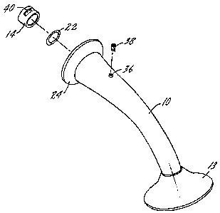
Fig. 1 is an exploded perspective of the modular shower arm assembly of the
present invention; and
Fig. 2 is an axial section through the shower arm assembly of Fig. 1.
2

CA 02333827 2001-02-05
DESCRIPTION OF THE PREFERRED EMBODIMENT
The present invention relates to a mounting system for shower fixtures, such
as
shower heads, but it can also have application to the mounting of bathtub
spouts. More
specifically, the invention pertains to a mounting system in which the
visible, normally
decorative, elements of a shower fixture installation may be removed and
replaced in
connection with changing the decor of a bathroom or lavatory without affecting
the water
supply pipe connection which is normally located behind the shower stall wall.
Most homeowners are reluctant to remove an existing shower fixture, as this
usually dictates that the connecting pipe must be unscrewed from a fitting
behind the shower
wall. Homeowners usually prefer that this function be performed by a licensed
plumber. The
present invention provides a mounting system in which all of the decorative
components may
be replaced without in any way altering or removing the water supply pipe
which protrudes
through the shower stall wall and is connected to the water supply system
behind the wall.
The components of the mounting system are all positioned on the water supply
pipe in a
manner in which they may be simply and easily removed with normal hand tools.
The
components which provide the connection between the shower fixture and the
pipe are
normally hidden from view with the exception of a set screw which extends down
through the
top of the tubular shower arm through an opening which is normally not visible
from someone
using the shower fixture. The components forming the connection slide over the
conventional
copper pipe or "stubout" which extends through the shower stall wall.
In Fig. 1 the components forming the shower fixture installation include a
tubular shower arm 10 having an exterior decorative appearance and a threaded
end 12 for the
3

CA 02333827 2001-02-05
mounting of a shower fixture such as a shower head 13. There is an adapter
sleeve 14 which
will form a portion of the connection between the tubular shower arm and the
copper pipe 16
which extends through the front face 18 of the wall 20 of the shower stall.
There is a seal ring
22 which will prevent water flowing through the tubular shower arm to the
shower fixture
from dripping out through the installation elements.
Focusing on Fig. 2, the tubular shower arm 10 has an enlarged curved surface
24 which may function as the escutcheon and which will bear against the
surface 18 of the wall
20 when the shower installation is complete. There is a water passage 26
within the tubular
shower arm for the flow of water to the shower fixture. The passage 26
includes a chamber 28
having a circumferential cylindrical wall 30 and a radially extending wall 32.
The chamber 28
receives the adapter sleeve 14. The inner diameter of the adapter sleeve
closely approximates
the outer diameter of the pipe 16. This enables the sleeve 14 to be slid over
the pipe, but yet
to be fixed to the exterior of the pipe. Directly adjacent the chamber 28 is a
second chamber
34 within which is positioned the seal ring 22. The ring 22 seals at its inner
diameter to the
pipe 16 and at its outer diameter to the chamber 34 forming a portion of the
water passage of
the tubular shower arm 10. The passage 26 has a portion 40 directly adjacent
chamber 34
which is sized to closely fit on pipe 16.
The tubular shower arm has a threaded opening 36 within which will be
threaded a set screw 38. The opening 36 for the set screw is at the top of the
upper surface of
the tubular shower arm where it is normally not visible to someone using the
fixture. The
sleeve 14 has an arcuate slot 40 through which the set screw 38 will pass when
attaching the
arm 10 to pipe 16.
4

CA 02333827 2001-02-05
In use, the first step in installation is to position the seal ring 22 within
its
chamber 34 in the tubular shower arm 10. Next, the adapter sleeve 14 is
positioned within its
chamber 28 so that the sleeve abuts the radial wall 32. The arcuate slot 40 in
the adapter
sleeve 14 should be positioned in alignment with the opening 36 in the tubular
shower arm.
The set screw is then inserted to hold the seal ring and sleeve within the
shower arm. This
combination of elements is then slid onto pipe 16 and moved inwardly onto the
pipe until the
escutcheon portion 24 of the tubular shower arm abuts the surface 18 of the
wall 20. The set
screw 38 may then be turned down until it bites into the outer surface of the
copper pipe 16.
This completes the installation.
If it is desired to change the shower arm and the shower head or fixture, the
first
step is to remove the shower head from the threaded connection 12 on the
tubular shower arm
10. This may not be necessary if the shower head is to be changed. Next, the
set screw 38 is
backed off, permitting removal of the shower arm 10, the seal ring 22 and the
adapter sleeve
14 from the copper pipe 16. This combination of elements may then be changed
to one of a
different exterior appearance and the assembly process is then followed to
install the new
fixture.
Whereas the preferred form of the invention has been shown and described
herein, it should be realized that there may be many modifications,
substitutions and alterations
thereto.
5

Dessin représentatif
Une figure unique qui représente un dessin illustrant l'invention.
États administratifs

2024-08-01 : Dans le cadre de la transition vers les Brevets de nouvelle génération (BNG), la base de données sur les brevets canadiens (BDBC) contient désormais un Historique d'événement plus détaillé, qui reproduit le Journal des événements de notre nouvelle solution interne.

Veuillez noter que les événements débutant par « Inactive : » se réfèrent à des événements qui ne sont plus utilisés dans notre nouvelle solution interne.

Pour une meilleure compréhension de l'état de la demande ou brevet qui figure sur cette page, la rubrique Mise en garde , et les descriptions de Brevet , Historique d'événement , Taxes périodiques et Historique des paiements devraient être consultées.

Historique d'événement

Description Date
Inactive : CIB désactivée 2021-10-09
Inactive : CIB en 1re position 2019-12-24
Inactive : CIB attribuée 2019-12-24
Inactive : CIB expirée 2018-01-01
Réputée abandonnée - omission de répondre à un avis sur les taxes pour le maintien en état 2007-02-05
Demande non rétablie avant l'échéance 2007-02-05
Inactive : Morte - RE jamais faite 2007-02-05
Inactive : CIB de MCD 2006-03-12
Inactive : Abandon.-RE+surtaxe impayées-Corr envoyée 2006-02-06
Exigences relatives à la révocation de la nomination d'un agent - jugée conforme 2004-11-19
Exigences relatives à la nomination d'un agent - jugée conforme 2004-11-19
Inactive : Lettre officielle 2004-11-19
Demande visant la révocation de la nomination d'un agent 2004-11-03
Demande visant la nomination d'un agent 2004-11-03
Demande publiée (accessible au public) 2001-08-15
Inactive : Page couverture publiée 2001-08-14
Inactive : CIB en 1re position 2001-04-09
Inactive : CIB attribuée 2001-04-09
Lettre envoyée 2001-03-06
Exigences de dépôt - jugé conforme 2001-03-06
Inactive : Certificat de dépôt - Sans RE (Anglais) 2001-03-06
Demande reçue - nationale ordinaire 2001-03-05

Historique d'abandonnement

Date d'abandonnement Raison Date de rétablissement
2007-02-05

Taxes périodiques

Le dernier paiement a été reçu le 2006-01-20

Avis : Si le paiement en totalité n'a pas été reçu au plus tard à la date indiquée, une taxe supplémentaire peut être imposée, soit une des taxes suivantes :

  • taxe de rétablissement ;
  • taxe pour paiement en souffrance ; ou
  • taxe additionnelle pour le renversement d'une péremption réputée.

Les taxes sur les brevets sont ajustées au 1er janvier de chaque année. Les montants ci-dessus sont les montants actuels s'ils sont reçus au plus tard le 31 décembre de l'année en cours.
Veuillez vous référer à la page web des taxes sur les brevets de l'OPIC pour voir tous les montants actuels des taxes.

Historique des taxes

Type de taxes Anniversaire Échéance Date payée
Taxe pour le dépôt - générale 2001-02-05
Enregistrement d'un document 2001-02-05
TM (demande, 2e anniv.) - générale 02 2003-02-05 2003-01-17
TM (demande, 3e anniv.) - générale 03 2004-02-05 2004-02-02
TM (demande, 4e anniv.) - générale 04 2005-02-07 2005-01-31
TM (demande, 5e anniv.) - générale 05 2006-02-06 2006-01-20
Titulaires au dossier

Les titulaires actuels et antérieures au dossier sont affichés en ordre alphabétique.

Titulaires actuels au dossier
MOEN INCORPORATED
Titulaires antérieures au dossier
JOHN E. BERTRAND
MICHAEL A. BRATTOLI
Les propriétaires antérieurs qui ne figurent pas dans la liste des « Propriétaires au dossier » apparaîtront dans d'autres documents au dossier.
Documents

Pour visionner les fichiers sélectionnés, entrer le code reCAPTCHA :


Pour visualiser une image, cliquer sur un lien dans la colonne description du document. Pour télécharger l'image (les images), cliquer l'une ou plusieurs cases à cocher dans la première colonne et ensuite cliquer sur le bouton "Télécharger sélection en format PDF (archive Zip)" ou le bouton "Télécharger sélection (en un fichier PDF fusionné)".

Liste des documents de brevet publiés et non publiés sur la BDBC .

Si vous avez des difficultés à accéder au contenu, veuillez communiquer avec le Centre de services à la clientèle au 1-866-997-1936, ou envoyer un courriel au Centre de service à la clientèle de l'OPIC.


Description du
Document 
Date
(aaaa-mm-jj) 
Nombre de pages   Taille de l'image (Ko) 
Dessin représentatif 2001-08-08 1 5
Abrégé 2001-02-04 1 15
Description 2001-02-04 5 208
Revendications 2001-02-04 2 52
Dessins 2001-02-04 1 22
Courtoisie - Certificat d'enregistrement (document(s) connexe(s)) 2001-03-05 1 113
Certificat de dépôt (anglais) 2001-03-05 1 162
Rappel de taxe de maintien due 2002-10-07 1 109
Rappel - requête d'examen 2005-10-05 1 115
Courtoisie - Lettre d'abandon (requête d'examen) 2006-04-17 1 166
Courtoisie - Lettre d'abandon (taxe de maintien en état) 2007-04-01 1 174
Correspondance 2004-11-02 4 122
Correspondance 2004-11-18 1 8
Correspondance 2004-11-18 1 15