Note: Descriptions are shown in the official language in which they were submitted.
CA 02333941 2000-11-30
WO 99/66152 PCT/SE99/00934
1
LOCKING SYSTEM AND FLOORING BOARD
The invention generally relates to a yccking sys-
tem for providing mechanical joining of floorboards.
More specifically, the invention concerns an improve-
ment of a locking system of the type described and shown
in WO 94/26999. The invention also relates to a floor-
board provided with such a locking system. According to
one more aspect of the invention, a floorboard with dif-
ferent designs of the locking system on long side and
short side is provided.
Field of the Invention
The invention is particularly suited for mechani-
cal joining of thin floating floorboards, such as lami-
nate and parquet flooring, and therefore the following
description of prior art and the objects and features
of the invention will be directed to this field of appli-
cation, in particular rectangular floorboards that are
joined on long sides as well as short sides. The features
distinguishing the invention concern in the first place
parts of the locking system which are related to hori-
zontal locking transversely of the joint edges of the
boards. In practice, floorboards will be manufactured
according to the inventive principles of also having
locking means for mutual vertical locking of the boards.
Background Art
WO 94/26999 discloses a locking system for mechani-
cal joining of building boards, especially floorboards.
A mechanical locking system permits locking together of
the boards both perpendicular to and in parallel with
the principal plane of the boards on long sides as well
as short sides. Methods for making such floorboards are
described in SE 9604484-7 and SE 9604483-9. The prin-
ciples of designing and laying the floorboards as well
CA 02333941 2006-11-22
22055-233
2
as the methods for making the same are described in the
above three documents.
With a view to facilitating the understanding and
description of the present invention as well as the
understanding of the problems behind the invention, now
follows with reference to Figs 1-3 a brief description
of floorboards according to WO 94/26999. This description
of prior art should in applicable parts be considered to
apply also to the following description of embodiments of
the present invention.
A floorboard 1 of known design is shown from below
and from above in Figs 3a and 3b, respectively. The board
is rectangular and has a top side 2, an underside 3, two
opposite long sides 4a, 4b which form joint.edges, and
two opposite short sides 5a, 5b which form joint edges.
Both the long sides 4a, 4b and the short sides Sa,
Sb can be joined mechanically without any glue in the
direction D2 in Fig. ic. To this end, the board 1 has a
planar strip 6 which is mounted at the factory and which
extends horizontally from one long side 4a, the strip
extending along the entire long side 4a and being made
of a flexible, resilient aluminium sheet. The strip 6
can be mechanically fixed according to the illustrated
embodiment, or fixed by means of glue or in some other
fashion. Other strip materials can be used, such as sheet
of some other metal, and aluminium or plastic sections.
Alternatively, the strip 6 can be integrally formed with
the board 1, for instance by some suitable working of the
body of the board 1. The strip, however, is always inte-
grated with the board 1, i.e. it is not mox;.nted on the
board 1 in connection with laying. The width of the strip
6 can be about 30 mm and its thickness about 0.5 mm. A
similar, although shorter strip 6' is arranged also along
one short side Sa of the board 1. The edge side of the
CA 02333941 2000-11-30
WO 99/66152 PCT/SE99/00934
3
strip 4 facing away from the joint edge 4a '_s formed with
a locking element 8 extending along the entire strip 6.
The locking element 8 has an active lockina surface 10
facing the joint edge 4a and having a height of e.g.
0.5 mm. In connection with laying, the locici~g element 8
cooperates with a locking groove 14, which is formed in
the underside 3 of the opposite long side 4b of an adja-
cent board 11. The short side strip 6' is provided with a
corresponding locking element 8', and the opposite short
side 5b has a corresponding locking groove 14'.
For mechanical joining of both long sides and short
sides also in the vertical direction (direction Dl in
Fig. lc), the board 1 is further along its cne long side
4a and its one short side 5a formed with a laterally open
recess 16. The recess 16 is defined downwards by the
associated strip 6, 6'. At the opposite edges 4b and 5b
there is an upper recess 18 defining a locking tongue 20
(see Fig. 2a) cooperating with the recess 16 to form a
tongue-and-groove joint.
Figs la-ic show how two such boards 1, 1' can be
joined by downwards angling. Figs 2a-2c show how the
boards 1, 1' can instead be.joined by snap action. The
long sides 4a, 4b can be joined by both methods whereas
the short sides 5a, 5b - after laying of the first row -
are normally joined after joining of the long sides and
merely by snap action. When a new board 1' and a pre-
viously laid board 1 are to be joined along their long
sides according to Figs la-ic, the long side 4b of the
new board 1' is pressed against the long side 4a of the
previously laid board 1 according to Fig. la, so that the
locking tongue 20 is inserted into the recess 16. The
board 1' is then angled downwards to the subfloor 12
according to Fig. lb. Now the locking tongue 20 complete-
ly enters the recess 16 while at the same time the lock-
ing element 8 of the strip 6 enters the locking groove
14. During this downwards angling, the upper part of the
locking element 8 can be active and accomplish a guiding
CA 02333941 2006-11-22
' 22055-233
4
of the new board 1' towards the previously laid board 1.
In the joined state according to Fig. lc, the boards 1,
1' are locked in both Dl direction and D2 direction, but
may be displaced relative to each other in the longitudi-
nal direction of the joint.
Figs 2a-2c illustrate how also the short sides 5a
and Sb of the boards 1, 1' can be mechanically joined in
both Dl and D2 direction by the new board 1' being moved
essentially horizontally towards the previously laid
board 1. This can be carried out after the long side 4b
of the new board 1' has been joined as described above.
in the first step in Fig. 2a, bevelled surfaces adjacent
to the recess 16 and the locking tongue 20 cooperate so
that the strip 6' is forced downwards as a direct conse-
quence of the joining of the short sides 5a, 5b. During
the final joining, the strip 6' snaps upwards as the
locking element 8' enters the locking groove 14'. By
repeating the operations shown in Figs 1 and .2, the.
entire floor can be laid without glue and along all joint
edges. Thus, prior-art floorboards of the above-mentioned
type are joined mechanically by, as a rule, first being
angled downwards on the long side, and when the long side
is locked, the short sides are snapped together by hori-
zontal displacement along the long side..The boards 1, 1'
can be taken up again in reverse order, without the joint
being damaged, and be laid once more.
For optimal function, it should be possible for the
boards, after being joined, along their long sides to
take a position where there is a possibility of a small
play between the locking surface 10 and the locking
groove 14.
In addition to the disclosure of the above-mentioned
patent specifications, Norske Skog Flooring AS (licensee
of Valinge Aluminium AB) introduced a laminate flooring
with a mechanical joining system according to WO 94/29699
in January 1996 in connection with the Domotex fair in
CA 02333941 2000-11-30
WO 99/66152 PCT/SE99/00934
Hannover, Germany. This laminate flooring marketed under
the trademark Allocis 7.6 mm thick, has a 0.6 mm alu-
minium strip 6 which is mechanically fixed to the tongue
side and the active locking surface 10 of the locking
5 element 8 has an inclination of about 70 -80 to the
plane of the board. The joint edges are impregnated with
wax and the underside is provided with underlay board
which is mounted at the factory. The vertical joint is
designed as a modified tongue-and-groove joint. The
strips 6, 6' on long side and short side are largely
identical, but slightly bent upwards to different
degrees on long side and short side. The inclination
of the active locking surface varies between long side
and short side. The distance of the locking groove 14
from the joint edge, however, is somewhat smaller on the
short side than on the long side. The boards are made
with a nominal play on the long side which is about
0.05-0.10 mm. This enables displacement of the long
sides and bridges width tolerances of the boards. Boards
of this brand have been manufactured and sold with zero
play on the short sides, which is possible since the
short sides need not be displaced in connection with the
locking which is effected by snap action. Boards of this
brand have also been made with more bevelled portions on
the short side to facilitate snapping in according to
Figs 2a-c above. It is thus known that the mechanical
locking system can be designed in various ways and that
long side and short side can be of different design.
WO 97/47834 (Unilin) discloses a mechanical joining
system which is essentially based on the above known
principles. In the corresponding product which this
applicant began to market in the latter part of 1997,
biasing between the boards is strived for. This leads tc
high friction and difficulties in angling together and
displacing the boards. This document also shows that the
mechanical locking on the short side can be designed in
a manner different from.the long side. In the described
CA 02333941 2000-11-30
WO 99/66152 PCT/SE99/00934
6
embodiments, the strip is integrated w=th the body of the
board, i.e. made in one piece with and of the same mate-
rial as the body of the board.
Summary of the Invention
Although the flooring according to WO 94/26999 and
the flooring marketed underthe trademark Alloc have
great advantages compared with traditional, glued floor-
ings, further improvements are desirable.
Mechanical joints are very suitable for joining not
only laminate floorings, but also wood floorings and com-
posite floorings. Such floorboards may consist of a large
number of different materials in the surface, the core
and the rear side, and as described above these materials
can also be included in the strip of the joining system,
the locking element on the strip, fixing surfaces, verti-
cal joints etc. This solution involving an integrated
strip, however, leads to costs in the form of waste when
the mechanical joint is being made. Alternatively, spe-
cial materials, such as the aluminium strip 6 above, can
be glued or mechanically fixed to the floorboard to be
included as components in the joining system. Different
joint designs affect the costs to a considerable extent.
A strip made of the same material as the body of the
board and formed by working of the body of the board can
in some applications be less expensive than an aluminium
strip, especially for floorboards in lower price ranges.
Aluminium, however, is more advantageous in respect of
flexibility, resilience and displaceability as well as
accuracy in the positioning of the locking element. Alu-
minium also affords the possibility of making a stronger
locking element. If the same strength is to be achieved
with a locking element of wood fibre, it must be wide
with a large shearing surface, which results in a large
amount of waste material in manufacture, or it must be
reinforced with a binder. Depending on the size of the
boards, working of, forinstance, 10 mm of a joint edge
CA 02333941 2000-11-30
WO 99/66152 PCT/SE99/00934
7
may result in six times higher cost of waste per m2 of
floor surface along the long sides compared with the
short sides.
In addition to the above problems relating to unde-
sirable waste of material, the present invention is based
on the insight that the long sides and short sides can be
optimised with regard to the specific locking functions
that should be present in these joint edges.
As described above, locking of the long side is, as
a rule, carried out by downwards angling. Also a small
degree of bending down of the strip during locking can
take place, as will be described in more detail below.
Thanks to this downwards bending together with an incli-
nation of the locking element, the boards can be angled
down and up again with very tight joint edges. The lock-
ing element along the long sides should also have a high
guiding capability so that the long side of a new board
in connection with downwards angling is pushed towards
the joint edge of the previously laid board. The locking
element should have a large guiding part. For optimal
function, the boards should along their long sides, after
being joined, be able to take a mutual position trans-
versely of the joint edges where there is a small play
between locking element and locking groove.
on the other hand, locking of the short side is car-
ried out by the long side being displaced so that the
strip of the short side can be bent down and snap into
the locking groove. Thus the short side must have means
which accomplish downwards bending of the strip in con-
nection with lateral displacement. The strength require-
ment is also higher on the short side. Guiding and dis-
placeability are less important.
Summing up, there is a great need for providing a
mechanical joint of the above type at a low cost and with
optimal locking functions at each joint edge. It is not
possible to achieve a low cost with prior-art solutions
without also lowering t.he requirements as to strength
CA 02333941 2006-11-22
22055-233
8
and/or laying function. An object of the invention is
to provide solutions which aim at lowering the cost with
maintained strength and function. According t:o the inven-
tion, these and other objects are achieved by a locking
system and a floorboard having the features as defined
in independent claims 1, 18, 23 and 25. Preferred embodi-
ments are stated in the respective dependent claims.
According to a first aspect of the invention,
a locking system for mechanical joining of
i0 floorboards is thus provided, where immediately juxta-
posed upper parts of two adjacent joint edges of two
joined floorboards together define a joint plane perpen-
dicular to the principal plane of the floor boards. To
obtain a joining of the two joint edges perpendicular to
the joint plane, the locking system comprises in a manner
known per se a locking groove which is formed in the
underside of and extends in parallel with the first'joint
edge at a distance from the joint plane, and a portion
projecting from the lower part of the second joint edge
and below the first joint edge and integrated with a body
of the board, said projecting portion supporting at a
distance from the joint plane a locking element cooperat-
ing with the locking groove and thus positioned entirely
outside the joint plane seen from the side of the second
joint edge, said projecting portion having a different
composition of materials compared with the body of the
board. The inventive locking system is characterisedin
that the projecting portion presents at least two hori-.
zontally juxtaposed parts, which differ from each other
at least in respect of the parameters material composi-
tion and material properties.
In a first embodiment of the first aspect of the
invention, said at least two parts of the projecting por-
tion are located at different distances from the joint
plane. In particular, they may comprise an inner part
closest to the joint plane and an outer part at a dis-
tance from the joint plane. The inner part and the outer
CA 02333941 2000-11-30
WO 99/66152 PCT/SE99/00934
9
part are preferably, but not necessarily, of equal length
in the joint direction. In this first aspect of the
invention, a material other than that included in the
body is thus included in the joining system, and in par-
ticular the outer part can be at least partially formed
of a separate strip which is made of a material other
than that of the body of the board and which is integral-
ly connected with the board by being factory-mounted. The
inner part can be formed at least partially of a worked
part of the body of the board and partially of part of
said separate strip. The separate strip can be attached
to such a worked part of the board body. The strip can be
located entirely outside said joint plane, but can also
intersect the joint plane and extend under the joint edge
to be attached to the body also inside the joint plane.
This embodiment of the invention thus provides a
kind of combination strip in terms of material, for exam-
ple a projecting portion comprising an inner part with
the material combination wood fibre/rear laminate/alumi-
nium, and an outer part of aluminium sheet.
It is also possible to make the projecting part from
three parts which are different in terms of material: an
inner part closest to the joint plane, a central part and
an outer part furthest away from the joint plane. The
inner part and the outer part can possibly be equal in
terms of material.
The portion projecting outside the joint plane need
not necessarily be continuous or unbroken along the joint
edge. A conceivable variant is that the projecting por-
tion has a plurality of separate sections distributed
along the joint edge. As an example, this can be accom-
plished by means of a separate strip with a continuous
inner part and a toothed outer part, said strip being
attachable to a part of the board body, said part being
worked outside the joint plane.
In an alternative embodiment of the first aspect of
the invention, said at least two parts, which differ in
CA 02333941 2006-11-22
22055-233
respect of at least one of the parameters material compo-
sition and material properties, are instead juxtaposed
seen in the direction parallel with the joint edges...For
example, there may be a plurality of strip types on one
S and the same side, where each strip type is optimised for
a special function, such as strength and guiding in con-
nection with laying. As an example, the strins can be
made of different aluminium alloys and/or of aluminium
having different states (for instance, as a result of
10 different types of heat treatment).
According to a second aspect of the inver.tion, '
a locking system for mechanical joini-ng of
floorboards is provided. In this second aspect of the
invention, the projecting portion is instead formed in
one piece with the body of the board and thus has the
same material composition as the body of the board. This
second aspect of the invention is characterised in that
the projecting portion, as a direct consequence of
machining of its upper side, presents at least two hori-
zontally juxtaposed parts, which differ from each other
in respect of at least one of the parameters material
composition and material properties.
The inventive principle of dividing the projecting
portion into several parts which differ from each other
in terms of material and/or material properties thus is
applicable also to the prior-art "wood fibre strip".
In the same manner as described above for the first
aspect of the invention, these two parts can be located'
at different distances from the joint plane, and espe-
cially there may be three or more parts with different
material composition and/or material properties.
Optionally, two such parts can be equal in respect of
said parameters, but they may differ from a third.
In one embodiment, said two parts may comprise an
inner part closest to the joint plane and an outer part
at a distance from the joint plane. There may be further
parts outside the outer.part. Specifically, an outer part
CA 02333941 2000-11-30
WO 99/66152 PCT/SE99/00934
11
can be formed of fewer materials than an inner part. For
instance, the inner part may consist of wood fibre and
rear laminate, whereas the outer part, by machining from
above, consists of rear laminate only. In one embodiment,
the projecting portion may comprise - seen =rom the joint
plane outwards - an inner part, an outer part and, out-
side the outer part, a locking element supported by the
outer part. The locking element may differ from both
inner and outer part in respect of said material para-
meters.
The projecting portion may consist of three laminat-
ed layers, and therefore it is possible, by working from
above, to provide a locking system which, counted from
the top, has a relatively soft upper guiding part which
need not have any particular strength, a harder central
part which forms a strong active locking surface and
absorbs shear forces in the locking element, and a lower
part which is connected with the rest of the projecting
portion and which can be thin, strong and resilient.
Laminated embodiments can be suitable in such floor-
boards where the body of the board consists of, for
instance, plywood or particle board with several layers.
Corresponding layers can be found in the walls of the
locking groove. For plywood, the material properties can
be varied by changing the direction of fibres in the
layers. For particle board, the material properties can
be varied by using different chip dimensions and/or a
binder in the different layers. The board body can gene-
rally consist of layers of different plastic materials.
In the definition of the invention, the term "pro-
jecting portion" relates to the part or parts of the
board projecting outside the joint plane and having a
function in the locking system in respect of supporting
of locking element, strength, flexibility etc.
An underlay of underlay board, foam, felt or the
like can, for instance, be mounted even in the manufac-
ture of the boards on the underside thereof. The underlay
CA 02333941 2006-11-22
22055-233
12
can cover the underside up to the locking element, so
that the joint between the underlays will be offset rela-
tive to the joint plane F. Although such an underlay is
positioned outside the joint plane, it should thus not be
S considered to be included in the definition of the
projecting portion in the appended claims.'
In the aspect of the invention which relates to
embodiments with a projecting portion of the same mate-
rial as the body of the board, any thin material layers
which remain after working from above should in the same
manner not be considered to be included in the "project-
ing portion" in the cases where such layers do not con-
tribute to the locking function in respect of strength,
flexibility, etc. The same discussion applies to thin
glue layers, binders, chemicals, etc. which are applied,
for instance, to improve moisture proofing and strength.
According to a third.aspect of the invention
there is provided a floorboard presenting a
locking system according to the first aspect or the
second aspect of the invention as defined above. Several
possibilities of combining prior-art separate strips,
prior-art wood fi-bre strips and "combination strips"
according to the invention are available. These possi-
bilities can be used optionally on long side and short
side.
For the above aspects, the projecting portion of a
given joint edge, for instance a long side, has at least
two parts with different material composition and/or
material properties. For optimisation of a floorboard,
such a difference in materials and/or material proper-
ties, however, may be considered to exist between the
long sides and short sides of the board instead of within
one and the same joint edge.
According to a fourth aspect of the invention,
a rectangular floorboard is thus provided,
comprising a body and first and second locking means
-integrated with the body and adapted to provide a mecha-
CA 02333941 2000-11-30
WO 99/66152 PCT/SE99/00934
13
nical joining of adjacent joint edges of such floorboards
along long sides and short sides, respectively, of the
boards in a direction perpendicular to the respective
joint edges and in parallel with the principal plane of
the floorboards. According to this aspect of the inven-
tion, the floorboard is characterised in that said first
and second locking means differ in respect of at least
one of the parameters material composition and material
properties. Preferably, said first and second locking
means each comprise on the one hand a portion which
projects from a joint edge and which at a distance from
the joint edge supports a locking element and, on the
other hand, a locking groove, which is formed in the
underside of the body at an opposite joint edge for
engaging such a locking element of an adjacent board. At
least one of said locking means on the long side and the
short side may comprise a separate element which is inte-
grally fixed to the body of the board at the factory and
is made of a material other than that included in the
body of the board. The other locking means may comprise
an element which is formed in one piece with the body of
the board.
Within the scope of the fourth aspect of the inven-
tion, there are several possibilities of combination. For
example, it is possible to select an aluminium strip for
the long side and a machined wood fibre strip for the
short side or vice versa. Another example is that for
the short side or the long side a "combination strip"
according to the first and the second aspect of the
invention is selected, and for the other side a "pure"
aluminium strip or a "pure" worked wood fibre strip is
selected.
The above problem of undesirable costs of material
is solved according to the invention by the projecting
portion being made of different materials and/or material
combinations and thus specially adaptable to the selected
materials in the floorboard and the function and strength
CA 02333941 2008-01-21
22055-233
" 14
requirements that apply to the specific floorboard and that
are specific for long side and short side. This advantage
of the invention will be evident from the following
description.
Since different requirements are placed on the
long side and the short side and also the cost of waste
differs, improvements can also be achieved by the long side
and the short side being made of different materials or
combinations of materials. In some applications, the long
side can have, for instance, an aluminium strip with high
guiding capability and low friction whereas the short side
can have a wood fibre strip. In other applications, the
opposite is advantageous.
In some applications, there may also be a need for
different types of strip on the same side. The side may
consist of, for instance, a plurality of different strips
which are made of different aluminium alloys, have different
thicknesses etc. and in which certain parts are intended to
achieve high strength and others are intended to be used for
guiding.
According to another aspect of the present
invention, there is provided a rectangular floorboard
comprising a body and first and second locking means
integrated with the body and adapted to provide mechanical
joining of adjacent joint edges of such floorboards along
long sides and short sides, respectively, of the boards in a
direction perpendicular to the respective joint edges and in
parallel with a principal plane of the floorboards, said
first and second locking means differ from each other in
respect of at least one of material composition and material
CA 02333941 2008-01-21
220S5-233
14a
properties, and that at least one of said locking means at
the long side and short side comprises an element which is
formed in one piece with the body of the board.
According to still another aspect of the present
invention, there is provided a rectangular floorboard
comprising a body and first and second locking elements
integrated with the body and adapted to provide mechanical
joining of adjacent joint edges of such floorboards along
the long sides and short sides, respectively, of the boards
in a direction perpendicular to the respective joint edges
and in parallel with a principal plane of the floorboards,
said first and second locking elements differ from each
other in respect of at least one of material composition and
material properties, and that at least one of said locking
elements at the long side and short side comprises a
separate element which is integrally connected with the body
of the board at the factory and is made of a material other
than that included in the body of the board.
According to yet another aspect of the present
invention, there is provided a rectangular floorboard
comprising a body and first and second locking elements
integrated with the body and adapted to provide mechanical
joining of adjacent joint edges of such floorboards along
long sides and short sides, respectively, of the boards in a
direction perpendicular to the respective joint edges and in
parallel with a principal plane of the floorboards, said
first and second locking elements differ from each other in
respect of at least one of material composition and material
properties, and that at least one of said locking elements
at the long side and short side comprises an element which
CA 02333941 2006-11-22
22055-233
14b
is formed in one piece with the body of the board.
Different aspects of the invention will now be
described in more detail by way of examples with reference
to the accompanying drawings. The parts of the inventive
board which are equivalent to those of the prior-art board
in Figs 1-3 are provided with the same reference numerals.
Brief Description of the Drawings
Figs la-c illustrate in three steps a downwards
angling method for mechanical joining of long sides of
floorboards according to WO 94/26999.
Figs 2a-c illustrate in three steps a snap-in
method for mechanical joining of short sides of floorboards
according to WO 94/26999.
Figs 3 and 3b show a floorboard according to
WO 94/26999 seen from above and from below, respectively.
CA 02333941 2000-11-30
WO 99/66152 PCT/SE99/00934
Fig. 4 shows a floorboard with a locking system
according to a first embodiment of the invention.
Fig. 5 is a top plan view of a floorboard according
to Fig. 4.
5 Fig. 6a shows on a larger scale a broken-away corner
portion Cl of the board in Fig. 5, and Figs Gb and 6c are
vertical sections of the joint edges along the long side
4a and the short side 5a of the board in Fig. 5, from
which it is particularly evident that the long side and
10 the short side are different.
Figs 7a-c show a downwards angling method for mecha-
nical joining of long sides of the floorboard according
to Figs 4-6.
Fig. 8 shows two joined floorboards provided with
15 a locking system according to a second embodiment of the
invention.
Fig. 9 shows two joined floorboards provided with
a locking system according to a third embodiment of the
invention.
Figs 10-12 illustrate three different embodiments of
floorboards according to the invention where the project-
ing portion is formed in one piece with the body of the
board.
Description of Preferred Embodiments
A=first preferred embodiment of a floorboard 1 pro-
vided with a locking system according to the invention
will now be described with reference to Figs 4-7. The
shown example also illustrates the aspect of the inven-
tion which concerns differently designed locking systems
for long side and short side.
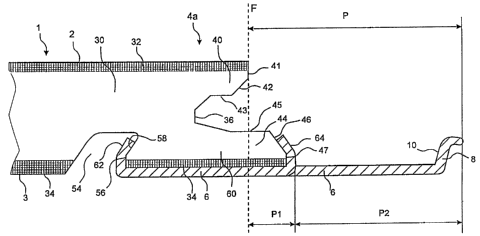
Fig. 4 is a cross-sectional view of a long side 4a
of the board.l. The:body of the board 1 consists of a
core 30 of, for instance, wood fibre which supports a
surface laminate 32 on its front side and a balance layer
34 on its rear side. The board body 30-34 is rectangular
with long sides 4a, 4b and short sides 5a, 5b. A separate
CA 02333941 2006-11-22
= 22055-233
16
strip 6 with a formed locking element 8 is mounted at the
factory on the body 30-34, so that the strip 6 consti-
tutes an integrated part of the completed floorboard I.
In the shown example, the strip 6 is made of resilient
aluminium sheet. As an illustrative, non-limiting exam-
ple, the aluminium sheet can have a thickness in the
order of 0.6 mm and the floorboard a thickness in the
order of 7 mm.
The strip 6 is formed with a locking element 8,
whose active locking surface 10 cooperates with a lock-
ing groove 14 in an opposite joint edge 4b of an adjacent
board 1' for horizontal locking together of the boards 1,
1' transversely of the joint edge (D2). With a view to
forming a vertical lock in the Dl direction, the joint
edge 4a has a laterally open groove 36 and the opposite
joint edge 4b has a laterally projecting tongue 38 (cor-
responding to the locking tongue 20), which in the joined
state is received in the groove 36 (Fig. 7c) . The free
surface of the upper part 40 of the groove 36 has a ver-
tical upper portion 41, a bevelled portion 42 and an
upper abutment surface 43 for the tongue 38. The free
surface of the lower part 44 of the groove 36 has a lower
abutment surface 45 for the tongue 38, a bevelled portion
46 and a lower vertical portion 47. The opposite joint
edge 4b (see Fig. 7a) has an upper vertical portion 48,
and the tongue 38 has an upper abutment surface 49, an
upper bevelled portion 50, a lower bevelled portion 51
and a lower abutment surface 52.
In the joined state (Fig. 7c), the two juxtaposed
vertical upper portions 41 and 48 define a vertical joint
plane F. As is best seen from Fig. 4, the lower part 44
of the groove 36 is extended a distance outside the joint
plane F. The joint edge 4a is in its underside formed
with a continuous mounting groove 54 having a vertical
lower gripping edge 56 and an inclined gripping edge 58.
CA 02333941 2000-11-30
WO 99/66152 PCT/SE99/00934
17
The gripping edges formed of the surfaces 46, 47, 56, 58.
together define a fixing shoulder 60 for mechanical fix-
ing of the strip 6. The fixing is carried out according
to the same principle as in the prior-art board and can
be carried out by means of the methods that are described
in the above-mentioned documents. A continuous lip 62 of
the strip 6 thus is bent round the gripping edges 56, 58
of the groove 54, while a plurality of punched tongues 64
are bent round the surfaces 46, 47 of the projecting por-
tion 44. The tongues 64 and the associated punched holes
65 are shown in the broken-out view in Fig. 6a.
There is a significant difference between the inven-
tive floorboard shown in Figs 4-7 and the prior-art board
according to Figs 1-3. The area P in Fig. 4 designates
the portion of the board 1 which is positioned outside
the joint plane 1. According to the invention, the por-
tion P has two horizontally juxtaposed parts P1 and P2,
which differ in respect of at least one of the parameters
material composition and material properties. More speci-
fically, the inner part P1 is, closest to the joint plane
F, formed partially of the strip 6 and partially of the
worked part 44 of the body. In this embodiment, the
inner part P1 thus comprises the material combination
aluminium + wood fibre core + rear laminate whereas the
outer part P2 is a made of aluminium only. In the prior-
art board 1 in Figs la-c, the corresponding portion out-
side the joint plane is made of aluminium only.
As described above, this feature of the invention
means that the cost of material can be reduced. Thanks to
the fact that the fixing shoulder 60 is displaced towards
the locking element 8 to such an extent that it is posi-
tioned at least partially outside the joint plane F, a
considerable saving can be achieved in respect of the
consumption of aluminium sheet. A saving in the order of
25% is possible. This embodiment is particularly advan-
tageous in cheaper floorboards where waste of wood fibre
as a result of machining of the body is preferred to a
CA 02333941 2000-11-30
WO 99/66152 PCT/SE99/00934
18
high consumption of aluminium sheet. The waste of mate-
rial, however, is limited thanks to the fact that the
projecting portion can also be used as abutment surface
for the tongue, which can then be made correspondingly
narrower perpendicular to the joint plane with the ensu-
ing reduced waste of material on the tongue side.
This constructional change to achieve saving in
material does not have a detrimental effect on the pos-
sibility of resilient vertical motion that must exist in
the projecting portion P. The strength of the locking
element 8 is not affected either. The outer part P2 of
aluminium is still fully resilient in the vertical direc-
tion, and the short sides 5a, 5b can be snapped together
according to the same principle as in Figs 2a-c. The
locking element 8 is still made of aluminium and its
strength is not reduced. However, it may be noted that
the degree of resilience can be affected since it is
essentially only the outer part P2 that is resilient in
the snap action. This can be an advantage in some cases
if one wants to restrict the bending-down properties and
increase the strength of the lock.
The angling together of the long sides 4a, 4b can
also be carried out according to the same principle as in
Fig.s la-c. In general - not only in this embodiment - a
small degree of downwards bending of the strip 6 may
occur, as shown in the laying sequence in Figs 7a-c. This
downwards bending of the strip 6 together with an incli-
nation of the locking element 8 makes it possible for the
boards 1, 1' to be angled down and up again with very
tight joint edges at the upper surfaces 41 and 48. The
locking element 8 should preferably have a high guiding
capability so that the boards, in connection with down-
wards angling, are pushed towards the joint edge. The
locking element 8 should have a large guiding part. For
optimal function, the boards should, after being joined
and along their long sides 4a, 4b, be able to take a
position where there is.a small play between locking ele-
CA 02333941 2000-11-30
WO 99/66152 PCT/SE99/00934
19
ment and locking groove, which need not be =reater than
about 0.02-0.05 mm. This play permits displacement and
bridges width tolerances. The friction in t:e joint
should be low.
In the joined state according to Fig. 'c, the boards
1, 1' are locked relative to each other in --he vertical
direction Dl. An upwards movement of the board 1' is
counteracted by engagement between the surfaces 43 and
49, while a downwards movement of the board 1' is coun-
teracted on the one hand by engagement between the sur-
faces 45 and 52 and, on the other hand, by -?:e board 1
resting on the upper side of the strip 6.
Fig. 8 shows a second embodiment of the invention.
The board 1 in Fig. 8 can be used for parquet flooring.
The board 1 consists of an upper wear layer 32a, a core
30 and a rear balance layer 34a. In this embodiment, the
projecting portion P outside the joint plane F is to a
still greater extent made of different combinations of
materials. The locking groove 14 is reinforced by the use
of a separate component 70 of, for instance, wood fibre,
which in a suitable manner is connected with the joint
edge, for instance by gluing. This variant can be used,
for instance, on the short side 5b of the board 1. More-
over, a large part of the fixing shoulder 60 is position-
ed outside the joint plane F.
Fig. 9 shows a third embodiment of the invention.
The board 1 in Fig. 9 is usable to provide a strong
attachment of the aluminium strip 6. In this embodiment,
a separate part 72 is arranged on the joint edge support-
ing the locking element 8. The part 72 can be made of,
for instance, wood fibre. The entire fixing shoulder 60
and the entire strip 6 are located outside the joint
plane F. Only a small part of the separate strip 6 is
used for resilience. From the viewpoint of material, the
portion P located outside the joint plane F has three
different areas containing the combinations of materials
"wood fibre only" (Pl),."wood fibre/balance layer/alumi-
CA 02333941 2000-11-30
WO 99/66152 PCT/SE99/00934
nium" (P2) and "aluminium only" (P3). This embodiment
with the fixing shoulder 6 positioned entirely outside
the joint plane F can also be accomplished merely by
working the body of the board, i.e. without the separate
5 part 72. The embodiment in Fig. 9 can be suitable for the
long side. The locking element 8 has a large guiding
part, and the projecting portion P outside the joint
plane F has a reduced bending down capability.
When comparing the embodiments in Figs 8 and 9, it
10 may be noted that in Fig. 9 the tongues 64 are higher
than the lip 62. This results in a strong attachment of
the strip 6 in the front edge of the fixing shoulder 60,
which is advantageous when bending down the strip 6. This
can be achieved without any extra cost of material since
15 the tongues 64 are punched from the existing material. On
the other hand, the lip 62 can be made lower, which is
advantageous in respect of on the one hand consumption of
material and, on the other hand, the weakening effect of
the mounting groove 54 on the joint edge. It should fur-
20 ther be noted that the locking element 8 in Fig. 8 is
lower, which facilitates the snapping in on the short
sides.
Figs 10-12 show three different embodiments of the
invention, in which the projecting portion can be made
in one piece with the board body or consists of separate
materials which are glued to the edge of the board and
are machined from above. Separate materials are particu-
larly suitable on the short side where strength and resi-
lience requirements are high. Such an embodiment means
that the composition of materials on the long side and
the short side can be different.
The above technique of providing the edge of the
body, on the long side and/or short side, with separate
materials that are fixed to the body to achieve special
functions, such as strength, moisture proofing, flexibi-
lity etc, can be used also without utilising the prin-
ciples of the invention. In other words, it is possible
CA 02333941 2000-11-30
WO 99/66152 PCT/SE99/00934
21
also in other joining systems, especially mechanical
joining systems, to provide the body with separate mate-
rials in this way. In particular, this material can be
applied as an edge portion, which in some suitable
fashion is attached to the edge of the body and which
can extend over the height of the entire board or parts
thereof.
In a preferred embodiment, the edge portion is
applied to the body before the body is provided with all
outer layers, such as top layer and rear balance layer.
Especially, such layers can then be applied on top of the
fixed, separate edge portion, whereupon the latter can be
subjected to working in respect of form with a view to
forming part of the joining system, such as the project-
ing portion with locking element and/or the tongue with
locking groove.
In Figs 10 and 11, the board body is composed of
a top laminate 32, a wood fibre core 30 and a rear lami-
nate 34. The locking element 8 is formed by the project-
ing portion P being worked from above in such manner
that, seen from the joint plane F outwards, it has an
inner part P1 consisting of wood fibre 30 and laminate
34, a central part P2 consisting of laminate 34 only, and
an outer part P3 consisting of wood fibre and laminate
34.
The embodiments in Figs 10 and 11 differ from each
other owing to the fact that in Fig. 10 the boundary
between the wood fibre core 30 and the rear laminate 34
is on a vertical level with the lower edge of the active
locking surface 10. Thus, in Fig. 10 no significant work-
ing of the rear laminate 34 has taken place in the cen-
tral part P2. On the other hand, in Fig. 11 also the rear
laminate 34 has been worked in the central part P2, which
gives the advantage that the active locking surface 10
of the locking element 8 is wholly or partly made of a
harder material.
CA 02333941 2006-11-22
22055-233
22
The embodiment in Fig. 12 differs from the embodi-
ments in Figs '10 and 11 by an additional intermediate
layer 33 being arranged between the wood fi-bre core 30
and the rear laminate 34. The intermediate layer 33
should be relatively hard and strong to reinforce the
active locking surface 10 as shown in Fig.* 12. For exam-
ple, the immediate layer 33 can be made of a separate
material which is glued to the inner core. Alternatively,
the immediate layer 33 may constitute a part of, for
instance, a particle board core, where chip material and
binder have been specially adapted to the mechanical
joining system. In this alternative, the core and the
intermediate layer 33 can thus both be made of chip mate-
rial, but with different properties. The layers can be
optirnised for the different functions of the locking sys-
tem.
Moreover, the aspects of the invention including
a separate strip can preferably be implemented in combi-
nation with the use of an equalising groove. Adjacent joint
edges are equalised in the thickness direction by working
of the underside, so that the upper sides of the floorboards
are flush when the boards are joined. Reference letter E in
Fig. la indicates that the body of the boards after such
working has the same thickness in adjacent joint edges.
The strip 6 is received in the groove and will thus be
partly flush-mounted in the underside of the floor. A.
corresponding arrangement can thus be,accomolished also
in combination with the invention as shown in the draw-
ings.