Note: Descriptions are shown in the official language in which they were submitted.
CA 02333983 2008-04-18
TRANSFER JIG FOR DENTAL IMPLANTS AND METHOD FOR
MAKING A MODEL
This invention relates to a method for making a
model for a dental prosthesis for mounting in a dental
foundation member such as an implant having an internal
hex, the implant being embedded in a jawbone of a
patient, and a dental formation mounting arrangement for
use in such a method.
After a period of, for example, three to six months,
has been allowed for an implant in the jawbone of a
patient to settle, it is usual for an impression to be
made in a plastic material of the surfaces of at least
part of the gum, and any adjacent teeth that surround the
embedded implant. The impression is then used to make
a model of that part of the gum and the adjacent teeth.
A dental technician uses the model to make a dental
prosthesis, which may be in the form of a false tooth,
for fitting into a socket in the implant.
An integrated implant prosthesis must fit accurately
and be designed to optimise stress distribution to the
supporting bone. It is therefore essential for this
prosthetic restoration of an implant that the position
of each implant in a jaw bone be accurately recorded and
CA 02333983 2007-08-28
2
transferred to the model. This is particularly important
for a screw retained prosthesis.
In practice, relative orientation of the implant to
the desired orientation of the dental prosthesis it is
to support is unpredictable, both because the actual
location of the settled implant is difficult to predict
and because the dental surgeon may have to overcome one
or more of a number of problems when implanting the
implant which means that the orientation of the implant
may differ from the optimum.
W093/20774 discloses a dental formation mounting
arrangement comprising a locating element which is
adapted to be engaged in a socket formed in a dental
foundation member on which the dental formation is to be
mounted so as to be held against rotation relative to the
dental foundation member and fixing means for fixing the
locating element to the foundation member when the
locating element is so engaged in the socket, wherein the
dental formation mounting arrangement comprises a
locating bush which is to be fitted over the locating
element, when the latter is engaged in the socket and
which is to carry said dental formation.
W093/20774 further discloses a method of making a
model of at least part of the gum utilising the dental
formation mounting arrangement described above. The
CA 02333983 2007-08-28
3
arrangement is described as comprising essentially three
components and, due to the configuration of the
components, requires the use of a non-standard impression
tray which is specific to the mounting arrangement.
W096/29019 discloses a dental formation mounting
arrangement including an anchor pin or post with an
elastic clamp head which is screwed into a tapped hole
in an implant which is implanted in the jawbone of a
patient, and a contoured element which is snap-fitted
onto the anchor pin. The contoured element may be an
impression cap or tray, a crown cap or a secondary pin
or post. The snap-fitting comprises an annular shoulder
which is formed internally on the contoured element and
which engages the elastic clamp head in a snap-fit
manner. The relative orientation of the contoured
element to the implement is imprecise because the anchor _
pin or post is screwed into the implant and the contoured
element can be fitted onto it at random.
According to one aspect of this invention there is
provided a dental formation mounting arrangement
including a locating element having a portion which is
formed so as to be a snug fit in a socket formed in a
dental foundation member on which a dental formation is
to be mounted, fixing means for fixing the locating
element to the foundation member when the locating
CA 02333983 2000-12-01
WO 99/62421 PCf1GB99/01734
4
element portion is fitted into the socket, and a mating
element attachable to and detachable from the locating
element by means which provide a snap-fit attachment,
wherein said locating element has a flat surface which
-5 is adapted to make face to face contact with a
corresponding flat surface of the socket when that
locating element portion is fitted into the socket
whereby to hold the locating element against rotation
relative to the dental foundation member and each of the
locating and mating elements is provided with a
respective formation, the formations on the locating and
mating elements being adapted to be positively
interengaged when the mating element is snap-fitted onto
the locating element and the mating element is in a
certain orientation relative to said flat surface.
Preferably the mating element is a hollow body
provided with apertures in its structure which place its
interior in communication with its surrounds, the
arrangement being such that, when the mating element is
embedded in dental impression material during a process
of making a dental impression, such dental impression
material can extend through the apertures and form
structural linksbetween such dental impression material
within the interior of the hollow body and such dental
impression material that surrounds the hollow body.
CA 02333983 2007-08-28
The means for providing a snap-fit may comprise at least
one locating member which protrudes from one of the
locating and mating elements, the at least one locating
member being locatable in a corresponding recess formed
5 in the other of the locating and mating elements, the at
least one locating member and the corresponding recess
serving as the formations. The at least one locating
member may comprise one or more locating pins and may
protrude from the locating element and be locatable in
a respective slot in the mating element.
In another embodiment the locating and mating
elements are adapted to be snap-fitted together by
pushing a projecting portion of one of them into a cavity
formed in the other and the formations include a wall
which extends partway around a mouth of the cavity and
which seats substantially without clearance in a
corresponding recess formed in the one of the locating
and mating elements, movement of the other element
relative to the one element in the direction that would
displace the wall around the periphery of the cavity
being stopped by abutment with the ends of the recess in
which the wall seats without substantial clearance.
Conveniently the locating elememt is formed from
metal and the mating element is formed from a plastics
material. The mating element may include at least one
CA 02333983 2000-12-01
WO 99/62421 PCT/GB99/01734
6
flange which is embedable in a dental impression material
in use, enabling the mating element to be removed with
the impression material once the impression material, has
set.
According to another aspect of this invention there
is provided a method for making a model of at least part
of the gum and one or more adjacent teeth that surround
one or more dental foundation members embedded in the
jawbone of a patient, said one or more dental foundation
members each having a receiving socket therein, the
method including the steps of:
(i) locating a locating element in the socket of
the or each dental foundation member;
(ii) attaching a mating eleinent to the locating
element by means of a snap-fit;
(iii) placing a dental impression tray filled with
dental impression material around the teeth, gums and the
or each dental foundation member;
(iv) removing the impression tray and dental
impression material with the mating element embedded
therein from the mouth of the patient by overcoming the
snap-fit holding the mating element on the locating
element once the dental impression material has set; and
(vii) forming a replica of the teeth and gums of the
patient using the impression created in the dental
i il
CA 02333983 2000-12-01
WO 99/62421 PCT/GB99/01734
7
.impression material once set, as a mould; wherein the
method also includes
(viii) providing the socket and a portion of the
locating element which is located in the socket with
mating flat faces which make face to face contact with
one another when the locating element is located in the
socket whereby the locating element is held
against rotation relative to the dental foundation
member; and
(ix) positively interengaging certain formations
provided on the locating and mating elements so that the
mating element is in a certain orientation relative to
said dental formation member.
Preferably the method includes the step of selecting
a hollow body as the mating element, the hollow body
having apertures in its structure which place its _
interior in communication with its surrounds and, filling
the interior with dental impression material so that it
extends through the apertures and forms structural links
between the dental impression material within the hollow
body and the dental impression material that surrounds
the body in the tray.
Three forms of transfer jig and a method for
forming a dental prosthesis for mounting in a dental
foundation member, such as an implant, which embodies
CA 02333983 2000-12-01
WO 99/62421 PCT/GB99/01734
8
.this invention are described,now by way of example with
reference to the accompanying drawings, of which:-
Figure 1 is a side elevation oJE one form of transfer
jig;
Figure 2 is a side elevation of the coping of the
transfer jig shown in Figure 1;
Figure 3 is.a side elevation of the post of the
transfer jig shown in Figure 1;
Figure 4 is a parts exploded side elevation of an
alternative transfer jig which includes the post of
Figure 3 and an alternative form of coping;
Figure 5 is a side elevation of the transfer jig of
Figure 4 in the assembled conditioin;
Figure 6 is a parts exploded perspective view of the
transfer jig of Figure 4;
Figure 7 is a section on the line VII-VII of Figure
5;
Figure 8 is a perspective view of another
alternative form of transfer jig;
Figure 9 is a perspective view of the transfer jig
shown in Figure 8 as seen from below in Figure 8;
Figures 10 and 11 are views similar to Figures 8 and 9
respectively of the parts of the transfer jig of Figures
8 and 9 shown separated;
Figure 12 is a side elevation of the inner tubular
CA 02333983 2000-12-01
WO 99/62421 PCT/GB99/01734
9
part of the coping of the transfer jig of Figures 8 to
11;
Figure 13 is a view on arrow A of Figure 12 of the
part shown in Figure 12;
Figure 14 is a side elevation of the outer tubular
part of the coping of the transfer jig of Figures 8 to
11;
Figure 15 is a view on arrow B of Figure 14 of the
part shown in Figure 14;
Figure 16 is an underneath plan view of the part
shown in Figure 14;
Figure 17 is a side elevation of the post of the
transfer jig shown in Figures 8 to 11;
Figure 18 is an underneath plari view of the post of
Figure 17; and
Figure 19 is a view on arrow C of Figure 17 of the
post shown in Figure 17.
After an implant has been i.mpla ted into the jawbone
of a patient, it is typical to allow the implant to
settle in the bone and to allow the bone to grow around
the implant over a period of, for example, three to six
months. Subsequently, but prior to making an impression
of the gum in which one or more implants have been
implanted, a dental surgeon fits a transfer jig into a
standard hexagonal socket of the or, each' implant by
CA 02333983 2007-08-28
removing the soft gum tissue that had grown over it since
it was implanted.
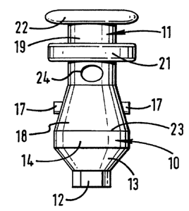
Figures 1 to 3 show the elements of such a transfer
jig are a first locating element 10, which is known as
5 a post, and a second mating element 11, which is known
as a coping and which is attachable and detachable from
the post 10 by means of a snap fit. Both the post 10 and
the coping 11 are generally tubular. The post 10, which
is conveniently formed of a metal such as titanium, has
10 a hexagonal portion 12 at one end for location in a
mating hexagonal socket of an implant (not shown). The
hexagonal portion 12 may be provided with one flat
surface which is adapated to abut a
corresponding flat suface formed in the socket of the
implant to hold the post 10 against rotation relative to
the implant.
The hexagonal portion 12 projects coaxially from the
smaller diameter end of one frusto-conical portion 13 of
the post 10. A cylindrical portion 14 extends coaxially
from the larger diameter end of the frusto-conical
portion 13 and is located between that frusto-conical
portion 13 and another coaxial frusto-conical portion 15.
The other frusto-conical portion 15 tapers away from the
cylindrical portion 14 and the diameter of its larger
diameter end is less than the diameter of the cylindrical
CA 02333983 2000-12-01
WO 99/62421 PCT/GB99/01734
11
portion 14 so that an annular shoulder 16 is formed
around it.
Two locating pins 17, which are integral with the
remainder of the post 10, project from the outer surface
of the other frusto-conical portion 15 and are located
substantially diametrically opposite one another.
A fixing screw (not shown) is insertable through the
bore of the generally tubular post 10, the threaded free
end of the screw being engageable with a threaded portion
in the socket of the implant (not shown) to which the
post 10 is to be attached, to secure the post 10 in place
with the hexagonal portion 12 located in the hexagonal
socket of the implant.
The coping 11, which is preferably made of plastics
material, has a hollow frusto-conical portion 18 at one
end. A cylindrical portion 19 extends coaxially from the
smaller diameter end of the frusto-conical portion 18 and
has an axially-spaced pair of radially-outwardly
extending annular flanges 21 and 22. The flange 21 is
intermediate the ends of the cylindrical portion 19. The
flange 22 is at the end of the cylindrical portion 19
that is remote from the frusto-conical portion 18.
The interior of the frusto-conical portion 18 of the
coping 11 is shaped to receive the frusto-conical portion
15 of the post 10 so as to seat thereon.
CA 02333983 2000-12-01
WO 99/62421 PCT/GB99/01734
12
Two opposing slots (not shown) are formed in the
walls of the frusto-conical portion.18 of the coping 11,
each being for receiving a respective one of the locating
pins 17 in a snap-fit manner. In a preferred embodiment
each slot is substantially keyhole-shaped having one
portion which extends from the rim 23 at the larger
diameter end of the frusto-conical portion 18 and which
is tapered and another portion which is an aperture and
which is at the smaller end of the tapered portion, the
width of the aperture being greater than the width of the
tapered portion at its smaller diameter end and being
sized so that a locating pin 17 fits snugly therein with
opposite sides of the slot in contact with opposite sides
of the locating pin 17 snap-fitted therein.
One or more apertures 24 extend through the walls
of the cylindrical portion 19 of the coping 11 between
the frusto-conical portion 18 and the nearer flange 21.
Figures 4 to 7 show an alternative form of generally
tubular coping 11A for use with the post 10. Parts of the
coping 11A which are similar to corresponding parts of
the coping 11 described above are identified by the same
reference number with A added.
Instead of the hollow frusto-conical portion 18 at
one end of the cylindrical portion 19A of the coping 11A,
the coping 11A has a hollow cylindrical portion 25 which
CA 02333983 2000-12-01
WO 99/62421 PCT/GB99/01734
13
has an outside diameter which is greater than that of the
cylindrical portion 19A. The exterior of the cylindrical
portion 19A between the intermediate flange 21A and the
larger diameter cylindrical portion 25 forms a concave
annular surface 26. Like the hollow frusto-conical
portion 18, the interior of the hollow cylindrical
portion 25 is shaped to receive the frusto-conical
portion 15 of the post 10 so as to seat thereon. Two
slots 27 are formed in the sidiawall of the hollow
cylindrical portion 25 to receive the locating pins 17.
The slots 27 are diametrically opposite one another and
each opens into the rim 23A of the cylindrical portion
25. The profile of each of the slots 27 is such as to
define a U-shaped base portion which extends into a
bulbous portion, the bulbous portion being at the smaller
end of a tapering portion, which tapers inwardly from the
rim 23A of the hollow cylindrical portion 25, and being
sized to snugly receive a locating pin 17 as shown in
Figure 5.
Figure 6 shows apertures 24A formed in the
cylindrical portion 19A on either side of the annular
flange 21A and angularly offset one with respect to
another about the axis of the generally tubular coping
11A. Each aperture 24A extends through the tubular wall
of the cylindrical portion 19A, communicating at its
CA 02333983 2007-08-28
14
inner end with the bore 28 (see Figure 7) of the coping
11A and being open at its other end in the outer surface
of the cylindrical portion 19A. The diameter of each
aperture 24A is substantially equal to the distance
between the flange 21A and the flange 22A of the hollow
cylindrical portion 25 respectively.
Figure 7 shows that the bore 29 of the post 10 is
stepped, comprising one bore portion which extends
through the hexagonal portion 12 and another, larger
diameter bore portion which extends to the other end. An
annular shoulder 31 separates the two portions of the
bore 29. The fixing screw 32 has an enlarged head which
seats on the shoulder 31. A hexagonal socket is formed
in the head of the fixing screw 32. Figure 7 also.shows
a screwdriver 33 inserted through the bore 28 of the
coping 11A.
The diameter of the bore 28 is less than that of the
larger diameter portion of the stepped bore 29 of the
post 10. The screwdriver 33 has a hexagonal end which is
fitted into the socket of the fixing screw 32 whereby the
fixing screw 32 is turned by turning the screwdriver 33.
It follows that the fixing screw 32 can be positioned
within the post 10 and the respective coping 11 or 11A
snap-fitted onto the post 10 by forcing the locating pins
17 into the respective keyhole slots 27 outside the mouth
CA 02333983 2000-12-01
WO 99/62421 PCT/GB99/01734
of the patient before the transfer jig is fitted into the
implant. The fixing screw 32 will be entrapped within the
coping 11 or 11A when the latter has been so assembled.
Figures 8 to 11 show another f'orm of transfer jig
5 which uses a different form of snap-fit connection
between a generally-tubular post 40 and a generally-
tubular coping 41. Also the coping 41 is angularly
located relative to the post 40 in a different way.
Like the post 10, the post 40 has a stepped through
10 bore 42 and a frusto-conical portion 43 which has a
hexagonal portion 44 projecting coaxially from its
smaller diameter end and a cyliindrical portion 45
extending coaxially from its larger diameter end. The
other end of the cylindrical portion 45 has a semi-
15 circular arcuate wall portion 46 projecting axially
beyond the semi-circular remainder. The diametrically _
opposed ends of the arcuate wall portion 46 form a co-
planar pair of spaced radially-extending surfaces 47 and
48. The larger diameter.bore portion 49 of the stepped
bore 42 tapers towards the annular shoulder 51 that
connects it to the smaller diameter bore portion 52. A
circumferentially-continuous arcuate resess 53 is formed
in the wall of the larger diameter bore portion 49
partway between the annular shoulder 51 and the arcuate
wall portion 46.
CA 02333983 2000-12-01
WO 99/62421 PCT/GB99/01734
16
The coping 41 is formed in two parts for
manufacturing convenience. One of its parts is a tubular
sleeve 54 and the other is an inner tubular member 55.
The tubular sleeve 54 has a semi-circular arcuate
wall portion 56 projecting axially beyond the semi-
circular remainder at one end. The diametrically opposed
ends of the arcuate wall portion 56 also form a co-planar
pair of radially extending surfaces 57 and 58.
The height of the arcuate wall portion 56 beyond the
semi-circular remainder of the respective end of the
sleeve 54 is the same as that of the arcuate wall portion
46 of the post 40.
Two pairs of diametrically-opposed apertures 59 and
61, 62 and 63 are formed to extend through the tubular
wall of the sleeve 54. Each pair of apertures 59 and 61,
62 and 63 is displaced angularly by about a right angle
as well as axially from the other pair of apertures 59
and 61, 62 and 63.
The inner tubular member 55 has; a radially-outwardly
extending flange 64 at one end. It is longer than the
tubular sleeve 54. It has an annular protuberance 65
formed at its other end, the surface of the protuberance
65 being a mirror image of thie circumferentially-
continuous arcuate recess 53 of the post 40.
The sleeve 54 is fitted over the inner tubular
CA 02333983 2000-12-01
WO 99/62421 PCT/GB99/01734
17
.member 55 so that its end remote from its arcuate wall
portion 56 abuts the flange 64 of the tubular member 55
which is a tight fit in it. The tubular member. 55
projects beyond the sleeve 54, as is shown in Figures 10
and 11, such that the annular protuberance 65 will be
seated in the arcuate recess 53 and the two arcuate wall
portions 46 and 56 will be seated on the semi-circular
remainder of the other part 40,54 with their
diametrically-opposed pair of radially extending surfaces
47 and 48, 57 and 58 in face to face abutment when the
two parts 40_and 41 are snap-fitted together as shown in
Figures 8 and 9 by pushing the projecting portion of the
inner tubular member 55 into the larger diameter end of
the tapered bore portion 49 of the tubular post 40.
Figures 12 and 13 show that the inner tubular member
55 has two pairs of apertures 66 and. 67, 68 and 69 formed
in it to extend through its tubular wall. The sizes,
spacing and angular orientation of 1these apertures 66 to
69 in the inner tubular member 55 aire substantially the
same as for the apertures 59 and Ei 1, 62 and 63 of the
sleeve 54. The inner tubular member 55 and the sleeve 54
are fitted together so that each aperture in one of them
is aligned with a respective apertu:re in the other such
that the resultant coping '41 has through apertures
communicating with its bore in the same way as does each
~.,
CA 02333983 2000-12-01
WO 99/62421 PCT/GB99/01734
18
.of the copings 11 and 11A.
The procedure for using a transfer jig which
includes a post 10 or 40 and a coping 11, 11A or 41 to
form a dental prosthesis for mouinting in an implant
involves inserting the fixing screw 32 into the bore of
the post 10,40 so that its threaded portion projects from
the open end 52 of the bore 29,42 of the hexagonal
portion 12,44, snap-fitting the coping 11,11A or 41 onto
the post 10 ,40 so that, in the case of the copings 11
and 11A, its rim 23,23A is seated on the annular shoulder
16 of the post 10, fitting the hexaclonal portion 12 into
the standard hexagonal socket of the implant that, is
implanted in the jawbone of the patient and screwing the
fixing screw 32 into the threaded hole in the implant,
using the screwdriver 33 that is iLnserted through the
bore 28 of the coping 11,11A or 41 and engaged in the
hexagonal socket formed in the head of the fixing screw
32. It is more convenient to assemble the post 10,40, the
fixing screw 32 and the coping 11,11A,41 outside the
mouth of the patient before the hexagonal portion 12,44
of the post 10,40 is fitted into the hexagonal socket of
the implant and secured in place by the fixing screw 32
rather than to fit the post 10,40 into the hexagonal
socket of the implant and to secure it in place before
the coping 11,11A,41 is snap-fitted onto the post 10,40.
CA 02333983 2007-08-28
19
Either way, the locating pins 17 positively engage the
sides of the slots 27 in the case of the post 10 , or the
radially extending surfaces 47 and 48, 57 and 58 are in
face to face abutment in the case of the post 40, whereby
the coping 11,11A,41 is spatially located with respect
to the hexagonal portion 12,44 which is fitted into the
hexagonal socket of the implant.
A standard impression tray filled with an impression
material, such as an elastomeric material, is inserted
into the mouth of the patient, over the teeth , gums and
transfer jig to create an impression. The impression
material is forced through the apertures 24,24A, 59, 61-
63, 66-69 in the cylindrical portion 19,19A, 54 and 55
of the coping 11,11A,41, into the bores 28 and 29, 42 of
the coping 11,11A,41 and around the flanges 21 and 22,
21A and 22, 64. Such impression material may be injected _
into the bores 28 and 29, 42 through the open end of the
coping 11,11A,41 remote from the post 10,40 since the
screwdriver 33 would have been removed. When the
impression material sets, the coping 11,11A,41 is locked
in place in the set material, the flanges 21 and 22, 21A
and 22A, 64 being embedded in the set material and the
impression material within the bores 28 and 29, 42 of the
coping 11,11A., 41 and the post 10, 40 being joined to the
impression material that surrounds the transfer jig by
CA 02333983 2000-12-01
WO 99/62421 PCT/GB99/01734
the branches of impression material that extend through
the apertures 24, 24A, 59,61-63, 65-69 and form
structural links between the impres;sion material within
and surrounding the transfer jig.
5 Once the impression material has set, the impression
tray is removed from the jaw, taking the impression
material and the coping 11,11A,41 with it, the coping
11,11A,41 being separated from the post 10,40 to which
it was snap-fitted. The post 10,40 may be removed from
10 the implant by unscrewing the fixing screw 32 holding it
in position, using the screwdriver 33. Alternatively, it
may be left in place to serve as a lleaiing collar while
the dental prosthesis is being made..
The dental technician then uses the resulting
15 impression as a mould to form a replica of the mouth of
the patient and gums to enable the appropriate size of
tooth or prosthesis to be made to the correct
orientation.
The mounting arrangement embodying the present
20 invention has a number of advantages, in particular, due
to the particular configuration of the arrangement, it
is not necessary for a special impression tray to be
used. Also, if only a single tooth or several teeth need
to be replaced, it may be possible to use the transfer
jig shown in Figures 1 to 3 when the implant is first
CA 02333983 2000-12-01
WO 99/62421 PCT/GB99/01734
21
inserted, and an impression of the teeth and gums of a
patient is taken at that stage. This eliminates the need
for exposing the implant at a later stage, for example
some three to six months after insertion of the implant,
to take the impression prior to inserting the final
tooth.
Various modifications will be appreciated by the
persom skilled in the art, for examiple, whilst the post
10, 40 has been described as being formed from a metal,
such as titanium, it could be formed from a plastics
material. Similarly the coping has been described as
being formed from a plastics material, however, other
materials could be used. Also, the number and position
of the apertures in the coping through which the
impression material is forced, nnay vary from that
illustrated and described above, as may the number, form
and location of the locating pins ar.id receiving slots or
other means for locating the coping with respect to the
hexagonal portion of the post.
Furthermore, the transfer jigs described above need
not be connected directly to an implant having an
internal hexagonal socket, but may be fitted to the
implant via an angled core (not shown). As a range of
differently angled cores are generally available, it is
possible to select the appropriately angled core for.the
CA 02333983 2000-12-01
WO 99/62421 PCT/GB99/01734
22
particular patient into which the transfer jigs described
above may be inserted.
In a further preferred embodiment, the post 10 may
have one or the other or both of the frusto-conial
portions and/or the interconnecting cylindrical portion
offset at an angle to the central :Longitudinal axis of
the hexagonal portion. The angle at which these portions
may be offset could be, for example, in the range 0 to
45 degrees. Also, it may be possible to construct the
aforementioned portions such that a variety of posts are
produced having differing angular oriLentations around the
axis of the hexagonal portion. The advantage of these
arrangements is that a mould in which the precise angular
orientation for the ultimate dental prothesis is formed
may be obtained.
The geometrical relationship between the hexagonal
portion 12,44 and the locating pins 17 or the radially-
extending surfaces 47 and 48 needs to be the same for all
posts 10, 40 so as to ensure interchangeability and
accurate reproduction of the orientation of the coping
11,11A,41 with respect to the implant in the resultant.
prosthesis.