Note: Descriptions are shown in the official language in which they were submitted.
CA 02333991 2000-12-O1
WO 99/64728 PCT/CA99/OU518
A SYSTEM FOR DELIVERING PRESSURI2~ED LUBRICANT FLUTDS TO
AN INTERIOR OF A ROTATING HOLLOW SHAFT
TECHNICAL FIELD
The present invention relates to the delivery of a
lubricant fluid to the interior of a rotating hollow
shaft and, in particular, to a system for such lubricant
fluid delivery into power shafts which operate at high
speed in high temperature environments.
BACKGROUND OF THE INVENTION
There are many mechanical constructions which
benefit from the delivery of lubricating fluid to an
interior of a rotating shaft. One such construction is
found in gas turbine engines where drive splines between
an internally splined drive shaft and an externally
splined driven shaft are lubricatE:d by a supply of
lubricant fluids trapped in an annular reservoir within
the drive shaft. In order to ensure a sufficient supply
of lubricant fluid in the annular reservoir, it is
desirable to deliver lubricant fluid to the reservoir
from a source. However, the centrifugal forces generated
by the rotation of the shaft tends to eject lubricant
fluid from the hollow shaft, so lubrication is difficult
to achieve using conventional methods of lubrication such
as immersion in lubricant fluid. Consequently, a
pressurized delivery system is required.
Systems for delivering a pressurized lubricant fluid
into a rotating hollow shaft, are known. For example,
U.S. Patent No. 5,129,905, which .issued on June 9, 1992
to Murray, describes an accessory drive spline
lubrication system for a turbine engine reduction gear
box. In this system, one or more nozzles spray a stream
of engine oil directed at an angle towards the axis of
CA 02333991 2000-12-O1
WO 99/64728 PCT/CA99/00518
- 2 -
the drive shaft and towards orifices in the drive shaft.
The nozzles are stationary relative to the drive shaft.
Each nozzle directs a stream of lubricant toward an
annular reservoir located near the splines, the streams
being aimed at the orifices. The streams of lubricant,
however, are intermittently interrupted by the rotation
of the drive shaft.
As a further example, U.S. Patent No. 5,246,087,
which issued on September 21, 1993 to Schippen, discloses
a device for radially transporting a medium to a rotating
station. The device includes a bearing assembly having a
stationary outer cylinder with a lubricant feed, an inner
cylinder which is rotatable together with a receiving
station that is coupled via rotation bearings to the
outer cylinder. The two sealing rings seal opposite ends
of the housing and form a passage for lubricant fluid
medium. The patent emphasizes that, in all conditions,
the medium for transfer (lubricating fluid) cannot leak
into the environment. This device is therefore
unsuitable for use in high temperature operating
environments such as encountered i.n turbine engines
because the leak-proof seals would likely fail under such
conditions.
Yet another example is disclosed in U.S. Patent
No. 4,251,186 which issued on February 17, 1981, to
Chomel et al. This patent discloses a device for
circulating fluid in a hollow shaft. The device includes
a fixed stator co-axial with the hollow shaft which
passes through it, forming an annular chamber around the
hollow shaft and a rotor within the chamber. The rotor
includes a plurality of radial bores. When the shaft is
rotated, a centrifugal force acts on the oil in the
radial bores to drive the oil into the chamber and to _
draw oil through a port around the shaft in the stator.
CA 02333991 2000-12-O1
. . .. .. .. .1.. .. ..
' .. ~. . . . . . . . . . . .
~ . . . 1 . v . ... . . . .
. . . ... . . . . . . . . ~
. . 1 . . . . . . . .
- 3 -. . .... .. .. ... .. ..
The pressure established in the chamber overcomes the
centrifugal force generated by rotation of the shaft and
drives the oil in the chamber through radial bores into an
interior of the hollow shaft. An annular separating wall
around the shaft within the chamber is fixed to the chamber
and defines, together with a sidewall of the stator,. an
annular intake chamber which directs the pressurized oil
into the radial hole of the shaft.
A drive shaft of a gas turbine engine typically
so operates at rotational speeds of up to about 6000 RPM and at
temperatures of up to about 93°C (200°F). As a result, to
be delivered to the interior of the hollow shaft lubricant
fluid must be under pressure.
A lubricant system used for the power shafts and
accessory drive shafts of gas turbine engines is located '
within a housing in which the shafts are rotatably mounted
and a certain amount of leakage is permitted. However,
leakage reduces the pressure at which t:he lubricant fluid is
delivered and seals having too much clearance are not
2o acceptable for applications such as the high speed, high
temperature and high lubricant fluid pressures associated
with gas turbine engines.
In order to permit the establishment of a minimum
leakage path between a rotor and a stator, Voitic suggests
in his U. S. Patent 3,333,856, issued on August 1, 2967, a
labyrinth-type seal having a pressure balanced face seal
relationship between the rotor and the stator. A pair of
seal rings floatingly mounted on a rotatable shaft are
axially spaced apart in an annular stationary housing. A
3o closing member is provided between the seal rings to define
an annular chamber within the annular housing and an inner
chamber between the seal rings and within the closing
member, fluid pressures are introduced to the respective
p~IEN~ED SHEET
CA 02333991 2000-12-O1
C
~ . . ~ . ~ . . . . . ~ . ~ . .
~ ~ ~ ~ ~ ~ ~ ~ . ~ ~ ~ f
~ ~ ~ ~ ~ ~ ~ ~ ~ ~ ~ ~ ~ .
. ~ . o.. . . ~ ~ . . . ~ .
. . . ~ ~ ~ ~ ~ . . v
_. . .... .. .. ... .. ..
annular chamber via an opening in the housing and to the
inner chamber through a passage extending axially in the
rotatable shaft and a bore aligned with the inner chamber to
establish the pressure balanced relationship. However, the
seals do not provide a passage to deliver lubricant fluid
from the stator to the axial passage in the rotatable shaft
because the space between the seal rings is closed to define
the two separate chambers for pressure balance.
SUl~lARY OF T8E INVENTION
to It is therefore an object of the invention to
provide a system for delivering pressurized lubricant fluids
to an interior of a rotating hollow shaft and to overcome
the shortcomings in the above discussed prior art.
It is another object of the invention to provide
~5 means for delivering pressurized lubricant fluid to an
interior of a rotating hollow shaft which operates at high
rotational speed and devoted temperatures.
In one aspect of the present invention, there is
provided an apparatus for delivering a pressurized lubricant
2o fluid from a stationary source to an interior of a hollow
shaft rotatably mounted in a housing, having a pair of seals
axially spaced apart and adapted to he mounted' around an
external periphery of the hollow shaft, the pair of seals
respectively having an inner periphery spaced from the
25 external periphery of the hollow shaft for promoting a
formation of a film of the lubricant fluid between the seals
and the hollow shaft while inhibiting' a free flow of the
lubricant fluid therebetween, the apparatus comprising: a
radial passage formed between the seals and having fluid
30 communication with the stationary source and the interior of
the hollow shaft, for directing a fluid flow past the seals
into the hollow shaft; and the seals being supported in an
axially restrained, radially unrestrained position with
p,MEidDED SHEET
CA 02333991 2000-12-O1
. . .1 .. .. .... .. ..
.~ .. ~ . a . . . a . . . .
. . . . . . . a ... . . . .
. . . ... . . . . . . . . v
. . . . . . . . . . .
-. . .... .. .. ... .. ..
respect to the housing so that the seals float on the film
of the lubricant fluid.
In another aspect of the present invention, there
is provided a method for delivering a ;pressurized lubricant
s fluid from a stationary source to an interior of a hollow
shaft rotatably mounted in a housing using a pair of seals
axially spaced apart and surrounding an external periphery
of the hollow shaft in an axially restrained, radially
unrestrained position with respect to the housing, an
io interior of each seal being spaced. radially from the
external periphery of the hollow shaft for promoting a
formation of a film of the lubricant fluid between the seals
and the hollow shaft while inhibiting' a free flow of the
lubricant fluid therebetween so that the seals float on the
1s film of the lubricant fluid, the method comprising:
providing a radial passage formed between the pair of
axially spaced-apart seals having fluid communication with
the source; providing at least one bore in the hollow shaft
which communicates with the interior of the hollow shaft and
2o aligns with the radial passage; and supplying pressurized
lubricant fluid from the source to the radial passage to
form the film of the lubricant upon which the seals float
and deliver the lubricant fluid into the interior of the
hollow shaft.
2s According to a further aspect of the present
invention, there is provided a system for delivering a
pressurized lubricant fluid from a stationary source to an
interior of a hollow shaft rotatably mounted in a housing
having a pair of seals axially spaced apart and surrounding
3o an external periphery of the hollow shaft, the pair of seals
respectively having an inner periphery spaced from the
external periphery of the hollow shaft for promoting a
formation of a film of the lubricant fluid between the seals
A~,~tfd~ED S~4~ET
CA 02333991 2000-12-O1
. . .w w. w1 ~w.. .. ww
w. .. . w s . . . w .
~
. w w . ~ ~ . . . .
w.w .
. . v w.. s w . . . .
. . v
. w w . w . . . .
~ .
~ ...~ .. ww www .. w~
5P.
and the hollow shaft while inhibiting a free flow of the
lubricant fluid therebetween, the apparatus comprising: a
radial passage formed between the pair of axially spaced-
apart seals and having fluid communication with the
stationary source; a retainer removably secured to the
housing and supporting the seals in an axially restrained,
radially unrestrained position with respect to the housing
so that the seals float on the film of the lubricant fluid;
and a bore in the hollow shaft in fluid communication with
so the radial passage and the interior of the hollow shaft so
that a fluid flow is directed inwardly from the stationary
source past the seals into the hollow :shaft.
The invention therefore provides an apparatus,
method and system for delivering lubricant fluid to an
interior of a drive shaft which rotates at high speed. The
apparatus comprises a pair of fluid seals which surround the
hollow shaft and flank a radial passage that has fluid
communication with a stationary source of pressurized
lubricant fluid. The seals are ax~.ally constrained but
2o radially unconstrained so that they float on a film of
lubricant that forms between the sealso and the drive shaft.
Wear of the seals and the shaft is
AMENDED SH~~~
CA 02333991 2000-12-O1
WO 99/64728 PCTICA99100518
- 6
thereby reduced. In order to control a width of the gap
and ensure that the thickness of the lubricant film is
consistent, a control ring is provided around each seal.
The control rings are bonded to the seals, and are
preferably made from the same material as the drive shaft
so that they have the same coefficient of thermal
expansion. The control rings ensure that a clearance
between the seals and the drive shaft is substantially
constant so that the film of lubricant fluid is formed
while a free flow of lubricant fluid between the seals
and the drive shaft is inhibited.
BRTEF DESCRIPTION OF THE DRAWINGS
The present invention will now be further described
by way of example only and with reference to the
accompanying drawings wherein:
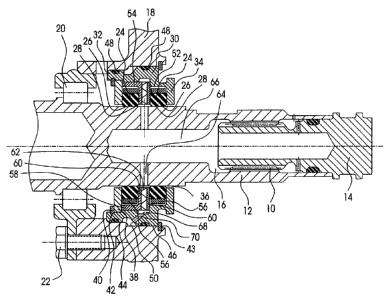
Fig. 1 is a cross-sectional view of an embodiment
showing the apparatus and system in accordance with the
present invention.
DETAILED DESCRIPTION OF THE PREFE7EtRED EMBODIMENT
As shown in Fig. 1, drive splines 10 between an
internally splined drive shaft 12 in a turbine engine and
an externally splined accessory driven shaft 14 are
lubricated by supply of lubricant fluid (not shown?
delivered to an annular reservoir 16. The hollow drive
shaft 12 is rotatably mounted in .a housing 18 via a
bearing set 20 which is secured to the housing with
bolts 22. A pair of seals 24 having a substantially
square cross-section surround the hollow drive shaft 12.
The seals 24 which are preferably carbon sealing rings
are spaced radially from the hollow drive shaft 12. A
clearance 26 between an inner periphery of each of the__
seals 24 and an external of the shaft 12 ensures a
CA 02333991 2000-12-O1
WO 99164728 PCT/CA99/00518
formation of a film 28 of the lubricant fluid
therebetween. A.cylindrical retainer 30 has an open
end 32 for inserting or removing the pair seals 24. The
cylindrical retainer 30 also has a closed end 34 with a
centric opening 36 for retaining the seals 24 from moving
axially in one direction while permitting the hollow
shaft to extend therethrough. A flat retainer washer 38
is provided at the open end 32 of the cylindrical
retainer 30 for retaining the seals 24 from axial
movement in the other direction, while permitting the
hollow drive shaft 12 to extend therethrough. The flat
retainer washer 38 is removably secured to the open
end 32 by a retainer washer clip.40 which is received
within an annular groove 42 at the open end 32 of the
cylindrical retainer 30. The retainer 30 is removably
inserted between an aperture in th.e housing 18 and the
hollow drive shaft 12 which aperture also receives the
hollow drive shaft and radially supports the bearing
set 20. The cylindrical retainer 30, is retained to the
housing by a retainer washer clip 43, includes a first
peripheral surface 44 of a first diameter, and a second
peripheral surface 46 of a second diameter larger than
the first. Each of the first and second peripheral
surfaces 44 and 46 radially retained by a corresponding
inner surface of the aperture in t:he housing 18 and
includes an 0-ring seal 48 therebetween. An annular
space 50 is defined between the first and second external
surfaces 44 and 46 and between the cylindrical
retainer 30 and the housing 18. ':Che cylindrical
retainer 30 has a inner periphery 52.
Each of the seals 24 is surrounded by an annular
control ring 56. The control rings 56 are preferably
rings having a coefficient of expansion similar to that...
of the drive shaft 12. Preferably, the control rings 56
CA 02333991 2000-12-O1
WO 99164728 PCT/CA99/00518
_ g _
are made of the same material as the drive shaft 12. The
function of the control rings 56 is to control the width
of the clearance 26 between the inner periphery of the
seals 24 and an outer periphery of the shaft 12, as will
be explained below in more detail.
A first of the seals 24 is positioned within the
cylindrical retainer 30, abutting t:he closed end 34,
radially spaced from the inner periphery 52 so that the
sealing ring 24 together with the control ring 56 is not
restrained from radial movement.
The second of the pair of seals 24 is positioned
within the cylindrical retainer 30 abutting the flat
retainer washer 38, which is secured to the open end 32
of the cylindrical retainer 30. The second seal 24 is
radially spaced from the inner periphery 54 and spacer 58
so that the seal 24 with its control ring 56 is not
restrained from radial movement.
Spacer 58 which includes two flat washers 60 with a
wave spring 62 therebetween is inserted between the
seals 24. The two flat washers 60 respectively abut one
of the seals 24 and the spring force exerted by the wave
spring 62 constantly urges the flat washer 60 against the
respective seals to prevent axial movement of the seals.
If the configuration of the wave spring does not form a
radial passage adequate to permit the lubricant fluid to
flow at a sufficient rate into the interior 66 of the
hollow drive shaft 12, one or more openings (not
illustrated) may be provided in th.e wave spring 62, to
increase the rate of flow through the radial passage
formed between the flat washer 60 therebetween. An inner
periphery of flat washers 60 are radially spaced from the
external periphery of the hollow drive shaft 12. The
spacer 58 is radially constrained by the inner _
periphery 54 of the retainer 30.
CA 02333991 2000-12-O1
WO 99!64728 PCTlCA99/005I8
- 9 -
The radial passage between the two flat washers 60
of the spacer 58 aligns with a plurality of radial
bores 64 which communicate with an interior 66 of the
hollow drive shaft 12. Provided in the middle of the
inner periphery 54 of the retainer 30 is an annular
groove 68 from which a channel 70 extends outwardly to
the annular space 50 to provide fluid communication
between the space 50 and the inter_Lor 66 of the hollow
drive shaft 12.
In operation, pressurized lubricant fluid is
introduced from a stationary source through passages in
the housing (not shown) into the annular space 50. The
pressurized lubricant fluid enters the radial passage
between the two flat washers 60 of the spacer 58 via the
channel 70 and the annular groove 68. The pressurized
lubricant fluid in the radial passage between the two
flat washers 60 overcomes the centrifugal force generated
by the rotating drive shaft 12 and discharges into the
interior 66 of the rotating hollow drive shaft 12.
Meanwhile, the lubricant fluid enters in the clearance 26
between the seals 24 and the rotating shaft 12 and forms
the lubricant film 28 therebetween. The first and second
seals 24 float on the film 28, so that they do not
directly contact the drive shaft 12. Wear of both the
seals 24 and the drive shaft 12 is thereby reduced.
It is essential that the drive shaft works properly
at very high speeds and high temperatures. Because of
fluctuations in operating temperature, the diameter of
both the rotating drive shaft and the seals change.
However, the changes in diameter a.re different due to the
difference of the coefficient of expansion of the
different materials of which the shaft and the seals are
respectively made. Therefore, the width of clearance 26
can vary, which may affect the performance of the
CA 02333991 2000-12-O1
WO 99164728 PCT/CA99100518
- 10 -
lubricant film 28. Consequently, the variation in the
width of clearance 26 is due to changes in the operating
temperature and is minimized by a c:ompensative force
exerted by the pair of control rings 56. The control
rings 56, as explained above, are rnade of a material
which has a coefficient of thermal expansion similar to
that of the material of which the rotating drive shaft 12
is made. The control rings 56 are bonded to the seals 24
and therefore control their expans:ion/contraction to
maintain the thickness of the lubricant changes.
Modifications to the above-described preferred embodiment
of the invention may become apparent to those skilled in
the art. The scope of the invention is therefore
intended to be limited solely by t:he scope of the
appended claims.