Language selection

Search

Patent 2334208 Summary

Third-party information liability

Some of the information on this Web page has been provided by external sources. The Government of Canada is not responsible for the accuracy, reliability or currency of the information supplied by external sources. Users wishing to rely upon this information should consult directly with the source of the information. Content provided by external sources is not subject to official languages, privacy and accessibility requirements.

Claims and Abstract availability

Any discrepancies in the text and image of the Claims and Abstract are due to differing posting times. Text of the Claims and Abstract are posted:

  • At the time the application is open to public inspection;
  • At the time of issue of the patent (grant).
(12) Patent Application: (11) CA 2334208
(54) English Title: A SAFETY DEVICE FOR MOVING THE LIFT CABIN IN CASE OF FAULT OF THE MAIN LIFTING SYSTEM
(54) French Title: DISPOSITIF DE SECURITE PERMETTANT DE DEPLACER UNE CABINE D'ASCENSEUR EN CAS DE DEFAILLANCE DU SYSTEME PRINCIPAL D'ASCENSEUR
Status: Deemed Abandoned and Beyond the Period of Reinstatement - Pending Response to Notice of Disregarded Communication
Bibliographic Data
(51) International Patent Classification (IPC):
  • B66B 05/02 (2006.01)
(72) Inventors :
  • FERRARI, CARLO (Italy)
(73) Owners :
  • OFFICINE FERRARI SNC DI CARLO E MARIO FERRARI & C.
(71) Applicants :
  • OFFICINE FERRARI SNC DI CARLO E MARIO FERRARI & C. (Italy)
(74) Agent: PERLEY-ROBERTSON, HILL & MCDOUGALL LLP
(74) Associate agent:
(45) Issued:
(86) PCT Filing Date: 1999-06-09
(87) Open to Public Inspection: 1999-12-23
Availability of licence: N/A
Dedicated to the Public: N/A
(25) Language of filing: English

Patent Cooperation Treaty (PCT): Yes
(86) PCT Filing Number: PCT/EP1999/004037
(87) International Publication Number: EP1999004037
(85) National Entry: 2000-12-04

(30) Application Priority Data:
Application No. Country/Territory Date
TO98A000514 (Italy) 1998-06-12

Abstracts

English Abstract


The invention concerns a safety device for moving a lift cabin (3) in case of
a fault of the main lifting system, comprising a platform (2) located under
the base (3a) of the lift cabin (3), engagement means (6, 8) for selectively
rendering said platform (2) integral with the lift shaft, and lifting means
(9, 10, 11) for lifting the cabin (3) in respect of the platform (2).


French Abstract

L'invention se rapporte à un dispositif de sécurité permettant de déplacer une cabine d'ascenseur (3) en cas de défaillance du système élévateur principal. Ce dispositif comporte une plate-forme (2) disposée sous la base (3a) de la cabine d'ascenseur (3), un dispositif d'accouplement (6, 8) permettant de solidariser sélectivement ladite plate-forme (2) et la gaine d'ascenseur, et un dispositif élévateur (9, 10, 11) conçu pour lever la cabine (3) par rapport à la plate-forme (2).

Claims

Note: Claims are shown in the official language in which they were submitted.

CLAIMS
1. A safety device for moving the cabin of a lift
system along a lift shaft in case of a fault of the
main lifting system, said device comprising:
- a platform (2) adapted to be mounted below the
base (3a) of said lift cabin (3);
- first engagement means (6, 8) located on said
platform (2) for selectively locking said platform
(2) to the lift shaft:
- lifting means (9, 10, 11) located on said platform
(2) acting to support the cabin on the platform
while lifting said cabin (3) in respect of said
platform (2) when said platform is locked to the
lift shaft through said first engagement means.
2. A device as claimed in claim 1, wherein said
platform (2) comprises second engagement means (4, 5)
for selectively rendering said platform (2) locked to
the base (3a) of said cabin (3).
3. A device as claimed in claim 2, wherein said
second engagement means (4, 5) comprises two pairs of
opposite oil cylinders (4), the extendable ends (4b) of
which can be inserted into corresponding holes (5)
laterally provided in the base (3a) of the cabin (3).
4. A device as claimed in any of the preceding
claims, wherein said first engagement means (6, 8)

comprises a pair, of jaws (6) adapted to clamp vertical
guides (7) provided inside the lift shaft in which said
cabin (3) is movable.
5. A device as claimed in claim 9, wherein each
of said jaws (6) comprises a pair of shoes (6a, 6b)
that can grip or release said guides (7) under the
control of oil pistons (8).
6. A device as claimed in any of the preceding
claims, wherein said lifting means (9, 10, 11)
comprises two vertical oil. cylinders (9).
7. A device as claimed in claim 6, wherein said
oil cylinders (9) are secured to said platform (2) and
are laterally. positioned to said cabin (3), in
correspondence of two opposed sides (3b).
8. A device as claimed in claim 7, wherein a
pulley (11) is located at the extendable end of said
oil cylinders (9), with a rope or chain (10) being
turned around said pulley, one end (10a) of said rope
or chain (10) being secured to said platform (2) and
the other end (10b) being laterally secured to said
cabin (3).
9. A device as claimed in any of the preceding
claims, wherein said platform (2) further carries a
battery (18), an electric motor (12a) and a pump for
pressurising the hydraulic circuit controlling said
engagement means and said lifting means.

10. A cabin for a lift system comprising a main
lifting system for moving the cabin along a lift shaft,
characterized in that said cabin comprises a safety
device as claimed in any of claims 1 to 9.
11. A lift system comprising a lift cabin (3) and
a main lifting system for moving the cabin along a lift
shaft, characterized in that it further comprises a
safety device as claimed in any of claims 1 to 9.

Description

Note: Descriptions are shown in the official language in which they were submitted.


CA 02334208 2000-12-04
WO 99/65813 1 PCT/EP99/04037
"A SAFETY DEVICE FOR MOVING THE LIFT CABIN IN CASE OF FAULT
OF THE MAIN LIFTING SY~'STEM".
to The present invention relates to a safety device for
moving the cabin of a lift or elevator in case of a fault
of the main lifting syatem.
More particularly,, the invention concerns an auxiliary
IS safety device for a lift system, adapted to displace
upwardly a car or cabin stopped between two floors, to the
level of the right above floor for allowing the passengers
disembar~:ation.
2~D As it is known when a sudden fault occurs in the main
lifting system of a lift, the cabin can stay blocked
between two floors at a level not allowing for the
evacuation of the passE~ngers.
25 Under the above circumstances it becomes necessary to
move the cabin eii.he:r upwardly or downwardly so as to
return the cabin t~ a level corresponding to the nearest
floor exit.
30 Italian patent No. 1 240 805 discloses a method for
moving the cabin of a lift or hoist that has accidentally
stopped between two floors.
In the system disclosed by patent No. 1 290 805 the
3i cabin is housed within a cage having a height at least
equal to the height of the cabin inclusive of its outer
service members and augmented by the distance between the
levels of two consecutive floor exits.
.to This cage is securely attached to the main lifting
system but the cabin can be displaced upwardly or
downwardly inside the cage through an auxiliary lifting
device.
-~5 In case the cabin remains trapped between two floors,
the cabin is caused to slidably move inside the cage, by
the safety device, until it reaches a floor exit.
The cabin movement inside the cage is stopped when the
5o cabin reaches the level of a floor exit, and then the lift
CONF~IHMATIpN CQPY

CA 02334208 2000-12-04
WO 99/65813 2 PCT/EP99/04037
door is opened to allow the passengers to evacuate the
cabin.
A first drawback of the method disclosed by Italian
patent No. 1 290 805 derives from the size of the cage in
which the cabin is housed.
Namely, due to the cage presence the lift shaft need
to be larger than usual, both in the lateral size and
height.
For this reason the method disclosed by the above
Italian patent cannot be employed in an already existing
lift system, unless the cabin size is rendered so small
IS that a properly dimensioned cage can be fitted inside the
existing shaft.
A first object of: the present invention is therefore
to overcome the above drawbacks by providing a safety
device that can be easily fitted to existing lift systems.
The method disclosed by the above Italian patent has
the further drawbac): of requiring a rather heavy metal
frame for housing the cabin.
30
As a consequence the lifting system must be designed
with a larger power rating in order to lift both the cage
and the cabin, thus increasing the costs for manufacturing
and operating the lift installation.
Another object of the present invention is therefore
to realize a safety device that is lightweight and
inexpensive to be manu:Eactured.
The above and other objects of the present invention
are achieved through a safety device for moving a lift
cabin in case of a ,fault of the main lifting system as
claimed in the attached claims.
Further characteristics and advantages of the
invention will become evident from the following
description of a preferred but not limiting embodiment
illustrated in the attached drawing in which:
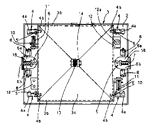
:IS Figure 1 is a to:p view of a cabin in a lift system
equipped with a device according to the invention;
Figure 2 is a partially cross-sectioned side view of
the cabin shown in Fig.. 1;
Figure 3 is a partially cross-sectioned side view of
5,~ the cabin shown in Fig. 1 from the opposed side with
respect of the view shown in Fig. 2.

CA 02334208 2000-12-04
WO 99/65813 3 PCT/EP99/04037
With reference to the attached Figures there is
illustrated a cabin 3 of a lift system, having a
substantially parallel.epipedal shape and comprising a base
3a, sides 3b and a roof 3c, such cabin being housed within
the shaft of a lift system, between two vertical guides or
rails 7.
The cabin 3 can be lifted and lowered along the lift
shaft by means of a main lifting system that is known in
the art and comprises a cable 13 secured to the roof :3c of
the cabin 3 through a loop 14.
The Figures further illustrate a safety device
according to the invention that comprises a platform 2,
having a substantially rectangular shape, formed by a metal
plate with the edge: folded by 90a, located under the base
3a of the cabin 3.
Said platform ~ can be selectively secured to or
rendered integral with the base ~a of the lift cablll 3 by
means of two pairs of opposite cil cylinders 4, each having
the body 4a secured to said platform 2 and the
corresponding piston ~~x~ extendable into corresponding holes
5 formed in the sides of the base 3a of. the cabin 3.
After the pistons 4b have been extended and inserted
into the holes 5, the platform 2 is rendered integral with
the cabin 3 and follows the upwardly or downwardly motion
thereof caused by the main lifting system.
Said platform ~' further comprises two pairs of
blocking jaws n, formed by shoes 6a, bb that can be clamped
to the vertical guides 7 provided in the lift shaft for
allowing the lift motion, thus rendering the platform 2
integral with the guides 7.
In correspondence of the guides 7 two rectangular
recesses 16 are provided in said platform 2, such recesses
being formed between the two shoes 6a, 6b for allowing the
insertion of the platform 2 between the guides 7.
The shoes 6a, 6b of each jaw 6 are driven by
corresponding oil cylinders 8,8 for closing and opening the
.~5 jaws 6 with respect to the guides 7.
Said platform 2 further carries two vertical oil
cylinders 9 laterally positioned in respect of two opposed
sides 3b of the cabin 3. When the vertical oil cylinders 9
30 are being extended each of them pulls - through a pulley 11
- a corresponding rope or chain 10 having one end l0a

CA 02334208 2000-12-04
WO 99/65813 ~ PCT/EP99/04037
secured to the platform 2 and the other end lOb laterally
fastened to the cabin 3 through loops 15 provided on the
two opposed sides of t:he cabin 3.
When the platform 2 is disengaged from the cabin 3 and
the cylinders 9 are being extended, the ropes IO are
tautened and as a consequence the cabin 3 is lifted in
respect of the platform 2.
On said platform 2 there are further disposed a
hydraulic circuit (not shown) for actuating the oil
cylinders 4, 8 and 9, and a hydraulic central unit 12 for
selectively actuating said oil cylinders 4, 8 and 9.
i5 Such hydraulic central unit 1~' further comprises an
electric motor 12a and a pump (not shown) for pressurising
the oil in the hydraulic circuit.
Further electronic and electromechanical devices are
:'o provided for actuating an automatic lifting cycle of the
cabin 3 in respect of the platform 2 and for actuating a
reverse cycle to restore the usual working conditions.
Such devices have not been disclosed and illustrated
5 since they are conventional and well known the the average
skilled person.
Moreover a battery 18 is secured to said platform 2
for feeding the electric motor I2a, the central unit 12 and
the other electrical and electromechanical devices.
The lifting cyclE~ of the cabin 3 in respect of the
platform 2 is carried. out when the cabin 3 accidentally
stops between two floors and becomes necessary to disembark
33 the passengers.
The cycle can bE~ started either through a control
member provided insidE~ the cabin 3 or through a control
member located outside the cabin.
The lifting cycle includes the following steps:
1. the main lifting system is de-energised;
2. through the oil pistons the shoes are clamped
against the guides 7 thus blocking together the frame 2 and
a5 the guides;
3. the pistons 9b are retracted into the oil cylinders
9 thus disengaging the cabin 3 from the platform 2;
4, the cabin 3, that is now free from the platform 2,
is lifted from the platform 2 (now blocked to the guides
5~) 7) , until it reaches t:he level corresponding to the right
above floor exit;

CA 02334208 2000-12-04
WO 99/65813 S PCT/EP99/04037
5. the door of the cabin 3 is opened to allow the
passengers to disembark:.
The reverse cycle is executed by repeating the above
'~ steps in reverse order.
It- is to be noted that when the cabin 3 is being
lifted from the platform 2, the cable 13 of the main
lifting system will become slac~~ and will rest upon the
1C~ roof of the cabin 2, without hindering the upwardly motion
of the cabin.
Although the invention has been disclosed with
particular reference t:o a preferred embodiment, all the
15 modifications and changes that will be evident to the
skilled in the art are to be considered as falling within
the scope of the invention.

Representative Drawing
A single figure which represents the drawing illustrating the invention.
Administrative Status

2024-08-01:As part of the Next Generation Patents (NGP) transition, the Canadian Patents Database (CPD) now contains a more detailed Event History, which replicates the Event Log of our new back-office solution.

Please note that "Inactive:" events refers to events no longer in use in our new back-office solution.

For a clearer understanding of the status of the application/patent presented on this page, the site Disclaimer , as well as the definitions for Patent , Event History , Maintenance Fee  and Payment History  should be consulted.

Event History

Description Date
Application Not Reinstated by Deadline 2005-06-09
Time Limit for Reversal Expired 2005-06-09
Deemed Abandoned - Failure to Respond to Maintenance Fee Notice 2004-06-09
Inactive: Abandon-RFE+Late fee unpaid-Correspondence sent 2004-06-09
Inactive: Cover page published 2001-03-28
Inactive: First IPC assigned 2001-03-18
Letter Sent 2001-03-07
Inactive: Notice - National entry - No RFE 2001-03-07
Application Received - PCT 2001-03-06
Application Published (Open to Public Inspection) 1999-12-23

Abandonment History

Abandonment Date Reason Reinstatement Date
2004-06-09

Maintenance Fee

The last payment was received on 2003-06-04

Note : If the full payment has not been received on or before the date indicated, a further fee may be required which may be one of the following

  • the reinstatement fee;
  • the late payment fee; or
  • additional fee to reverse deemed expiry.

Patent fees are adjusted on the 1st of January every year. The amounts above are the current amounts if received by December 31 of the current year.
Please refer to the CIPO Patent Fees web page to see all current fee amounts.

Fee History

Fee Type Anniversary Year Due Date Paid Date
Registration of a document 2000-12-04
Basic national fee - small 2000-12-04
MF (application, 2nd anniv.) - small 02 2001-06-11 2001-05-14
MF (application, 3rd anniv.) - small 03 2002-06-10 2002-05-29
MF (application, 4th anniv.) - small 04 2003-06-09 2003-06-04
Owners on Record

Note: Records showing the ownership history in alphabetical order.

Current Owners on Record
OFFICINE FERRARI SNC DI CARLO E MARIO FERRARI & C.
Past Owners on Record
CARLO FERRARI
Past Owners that do not appear in the "Owners on Record" listing will appear in other documentation within the application.
Documents

To view selected files, please enter reCAPTCHA code :


To view images, click a link in the Document Description column. To download the documents, select one or more checkboxes in the first column and then click the "Download Selected in PDF format (Zip Archive)" or the "Download Selected as Single PDF" button.

List of published and non-published patent-specific documents on the CPD .

If you have any difficulty accessing content, you can call the Client Service Centre at 1-866-997-1936 or send them an e-mail at CIPO Client Service Centre.


Document
Description 
Date
(yyyy-mm-dd) 
Number of pages   Size of Image (KB) 
Representative drawing 2001-03-27 1 12
Abstract 2000-12-03 1 57
Description 2000-12-03 5 232
Claims 2000-12-03 3 82
Drawings 2000-12-03 3 68
Reminder of maintenance fee due 2001-03-06 1 112
Notice of National Entry 2001-03-06 1 194
Courtesy - Certificate of registration (related document(s)) 2001-03-06 1 113
Reminder - Request for Examination 2004-02-09 1 113
Courtesy - Abandonment Letter (Request for Examination) 2004-08-17 1 166
Courtesy - Abandonment Letter (Maintenance Fee) 2004-08-03 1 175
PCT 2000-12-03 9 330
Fees 2003-06-03 1 26
Fees 2001-05-13 1 33