Sélection de la langue

Search

Sommaire du brevet 2334208 

Énoncé de désistement de responsabilité concernant l'information provenant de tiers

Une partie des informations de ce site Web a été fournie par des sources externes. Le gouvernement du Canada n'assume aucune responsabilité concernant la précision, l'actualité ou la fiabilité des informations fournies par les sources externes. Les utilisateurs qui désirent employer cette information devraient consulter directement la source des informations. Le contenu fourni par les sources externes n'est pas assujetti aux exigences sur les langues officielles, la protection des renseignements personnels et l'accessibilité.

Disponibilité de l'Abrégé et des Revendications

L'apparition de différences dans le texte et l'image des Revendications et de l'Abrégé dépend du moment auquel le document est publié. Les textes des Revendications et de l'Abrégé sont affichés :

  • lorsque la demande peut être examinée par le public;
  • lorsque le brevet est émis (délivrance).
(12) Demande de brevet: (11) CA 2334208
(54) Titre français: DISPOSITIF DE SECURITE PERMETTANT DE DEPLACER UNE CABINE D'ASCENSEUR EN CAS DE DEFAILLANCE DU SYSTEME PRINCIPAL D'ASCENSEUR
(54) Titre anglais: A SAFETY DEVICE FOR MOVING THE LIFT CABIN IN CASE OF FAULT OF THE MAIN LIFTING SYSTEM
Statut: Réputée abandonnée et au-delà du délai pour le rétablissement - en attente de la réponse à l’avis de communication rejetée
Données bibliographiques
(51) Classification internationale des brevets (CIB):
  • B66B 05/02 (2006.01)
(72) Inventeurs :
  • FERRARI, CARLO (Italie)
(73) Titulaires :
  • OFFICINE FERRARI SNC DI CARLO E MARIO FERRARI & C.
(71) Demandeurs :
  • OFFICINE FERRARI SNC DI CARLO E MARIO FERRARI & C. (Italie)
(74) Agent: PERLEY-ROBERTSON, HILL & MCDOUGALL LLP
(74) Co-agent:
(45) Délivré:
(86) Date de dépôt PCT: 1999-06-09
(87) Mise à la disponibilité du public: 1999-12-23
Licence disponible: S.O.
Cédé au domaine public: S.O.
(25) Langue des documents déposés: Anglais

Traité de coopération en matière de brevets (PCT): Oui
(86) Numéro de la demande PCT: PCT/EP1999/004037
(87) Numéro de publication internationale PCT: EP1999004037
(85) Entrée nationale: 2000-12-04

(30) Données de priorité de la demande:
Numéro de la demande Pays / territoire Date
TO98A000514 (Italie) 1998-06-12

Abrégés

Abrégé français

L'invention se rapporte à un dispositif de sécurité permettant de déplacer une cabine d'ascenseur (3) en cas de défaillance du système élévateur principal. Ce dispositif comporte une plate-forme (2) disposée sous la base (3a) de la cabine d'ascenseur (3), un dispositif d'accouplement (6, 8) permettant de solidariser sélectivement ladite plate-forme (2) et la gaine d'ascenseur, et un dispositif élévateur (9, 10, 11) conçu pour lever la cabine (3) par rapport à la plate-forme (2).


Abrégé anglais


The invention concerns a safety device for moving a lift cabin (3) in case of
a fault of the main lifting system, comprising a platform (2) located under
the base (3a) of the lift cabin (3), engagement means (6, 8) for selectively
rendering said platform (2) integral with the lift shaft, and lifting means
(9, 10, 11) for lifting the cabin (3) in respect of the platform (2).

Revendications

Note : Les revendications sont présentées dans la langue officielle dans laquelle elles ont été soumises.


CLAIMS
1. A safety device for moving the cabin of a lift
system along a lift shaft in case of a fault of the
main lifting system, said device comprising:
- a platform (2) adapted to be mounted below the
base (3a) of said lift cabin (3);
- first engagement means (6, 8) located on said
platform (2) for selectively locking said platform
(2) to the lift shaft:
- lifting means (9, 10, 11) located on said platform
(2) acting to support the cabin on the platform
while lifting said cabin (3) in respect of said
platform (2) when said platform is locked to the
lift shaft through said first engagement means.
2. A device as claimed in claim 1, wherein said
platform (2) comprises second engagement means (4, 5)
for selectively rendering said platform (2) locked to
the base (3a) of said cabin (3).
3. A device as claimed in claim 2, wherein said
second engagement means (4, 5) comprises two pairs of
opposite oil cylinders (4), the extendable ends (4b) of
which can be inserted into corresponding holes (5)
laterally provided in the base (3a) of the cabin (3).
4. A device as claimed in any of the preceding
claims, wherein said first engagement means (6, 8)

comprises a pair, of jaws (6) adapted to clamp vertical
guides (7) provided inside the lift shaft in which said
cabin (3) is movable.
5. A device as claimed in claim 9, wherein each
of said jaws (6) comprises a pair of shoes (6a, 6b)
that can grip or release said guides (7) under the
control of oil pistons (8).
6. A device as claimed in any of the preceding
claims, wherein said lifting means (9, 10, 11)
comprises two vertical oil. cylinders (9).
7. A device as claimed in claim 6, wherein said
oil cylinders (9) are secured to said platform (2) and
are laterally. positioned to said cabin (3), in
correspondence of two opposed sides (3b).
8. A device as claimed in claim 7, wherein a
pulley (11) is located at the extendable end of said
oil cylinders (9), with a rope or chain (10) being
turned around said pulley, one end (10a) of said rope
or chain (10) being secured to said platform (2) and
the other end (10b) being laterally secured to said
cabin (3).
9. A device as claimed in any of the preceding
claims, wherein said platform (2) further carries a
battery (18), an electric motor (12a) and a pump for
pressurising the hydraulic circuit controlling said
engagement means and said lifting means.

10. A cabin for a lift system comprising a main
lifting system for moving the cabin along a lift shaft,
characterized in that said cabin comprises a safety
device as claimed in any of claims 1 to 9.
11. A lift system comprising a lift cabin (3) and
a main lifting system for moving the cabin along a lift
shaft, characterized in that it further comprises a
safety device as claimed in any of claims 1 to 9.

Description

Note : Les descriptions sont présentées dans la langue officielle dans laquelle elles ont été soumises.

CA 02334208 2000-12-04
WO 99/65813 1 PCT/EP99/04037
"A SAFETY DEVICE FOR MOVING THE LIFT CABIN IN CASE OF FAULT
OF THE MAIN LIFTING SY~'STEM".
to The present invention relates to a safety device for
moving the cabin of a lift or elevator in case of a fault
of the main lifting syatem.
More particularly,, the invention concerns an auxiliary
IS safety device for a lift system, adapted to displace
upwardly a car or cabin stopped between two floors, to the
level of the right above floor for allowing the passengers
disembar~:ation.
2~D As it is known when a sudden fault occurs in the main
lifting system of a lift, the cabin can stay blocked
between two floors at a level not allowing for the
evacuation of the passE~ngers.
25 Under the above circumstances it becomes necessary to
move the cabin eii.he:r upwardly or downwardly so as to
return the cabin t~ a level corresponding to the nearest
floor exit.
30 Italian patent No. 1 240 805 discloses a method for
moving the cabin of a lift or hoist that has accidentally
stopped between two floors.
In the system disclosed by patent No. 1 290 805 the
3i cabin is housed within a cage having a height at least
equal to the height of the cabin inclusive of its outer
service members and augmented by the distance between the
levels of two consecutive floor exits.
.to This cage is securely attached to the main lifting
system but the cabin can be displaced upwardly or
downwardly inside the cage through an auxiliary lifting
device.
-~5 In case the cabin remains trapped between two floors,
the cabin is caused to slidably move inside the cage, by
the safety device, until it reaches a floor exit.
The cabin movement inside the cage is stopped when the
5o cabin reaches the level of a floor exit, and then the lift
CONF~IHMATIpN CQPY

CA 02334208 2000-12-04
WO 99/65813 2 PCT/EP99/04037
door is opened to allow the passengers to evacuate the
cabin.
A first drawback of the method disclosed by Italian
patent No. 1 290 805 derives from the size of the cage in
which the cabin is housed.
Namely, due to the cage presence the lift shaft need
to be larger than usual, both in the lateral size and
height.
For this reason the method disclosed by the above
Italian patent cannot be employed in an already existing
lift system, unless the cabin size is rendered so small
IS that a properly dimensioned cage can be fitted inside the
existing shaft.
A first object of: the present invention is therefore
to overcome the above drawbacks by providing a safety
device that can be easily fitted to existing lift systems.
The method disclosed by the above Italian patent has
the further drawbac): of requiring a rather heavy metal
frame for housing the cabin.
30
As a consequence the lifting system must be designed
with a larger power rating in order to lift both the cage
and the cabin, thus increasing the costs for manufacturing
and operating the lift installation.
Another object of the present invention is therefore
to realize a safety device that is lightweight and
inexpensive to be manu:Eactured.
The above and other objects of the present invention
are achieved through a safety device for moving a lift
cabin in case of a ,fault of the main lifting system as
claimed in the attached claims.
Further characteristics and advantages of the
invention will become evident from the following
description of a preferred but not limiting embodiment
illustrated in the attached drawing in which:
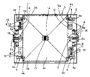
:IS Figure 1 is a to:p view of a cabin in a lift system
equipped with a device according to the invention;
Figure 2 is a partially cross-sectioned side view of
the cabin shown in Fig.. 1;
Figure 3 is a partially cross-sectioned side view of
5,~ the cabin shown in Fig. 1 from the opposed side with
respect of the view shown in Fig. 2.

CA 02334208 2000-12-04
WO 99/65813 3 PCT/EP99/04037
With reference to the attached Figures there is
illustrated a cabin 3 of a lift system, having a
substantially parallel.epipedal shape and comprising a base
3a, sides 3b and a roof 3c, such cabin being housed within
the shaft of a lift system, between two vertical guides or
rails 7.
The cabin 3 can be lifted and lowered along the lift
shaft by means of a main lifting system that is known in
the art and comprises a cable 13 secured to the roof :3c of
the cabin 3 through a loop 14.
The Figures further illustrate a safety device
according to the invention that comprises a platform 2,
having a substantially rectangular shape, formed by a metal
plate with the edge: folded by 90a, located under the base
3a of the cabin 3.
Said platform ~ can be selectively secured to or
rendered integral with the base ~a of the lift cablll 3 by
means of two pairs of opposite cil cylinders 4, each having
the body 4a secured to said platform 2 and the
corresponding piston ~~x~ extendable into corresponding holes
5 formed in the sides of the base 3a of. the cabin 3.
After the pistons 4b have been extended and inserted
into the holes 5, the platform 2 is rendered integral with
the cabin 3 and follows the upwardly or downwardly motion
thereof caused by the main lifting system.
Said platform ~' further comprises two pairs of
blocking jaws n, formed by shoes 6a, bb that can be clamped
to the vertical guides 7 provided in the lift shaft for
allowing the lift motion, thus rendering the platform 2
integral with the guides 7.
In correspondence of the guides 7 two rectangular
recesses 16 are provided in said platform 2, such recesses
being formed between the two shoes 6a, 6b for allowing the
insertion of the platform 2 between the guides 7.
The shoes 6a, 6b of each jaw 6 are driven by
corresponding oil cylinders 8,8 for closing and opening the
.~5 jaws 6 with respect to the guides 7.
Said platform 2 further carries two vertical oil
cylinders 9 laterally positioned in respect of two opposed
sides 3b of the cabin 3. When the vertical oil cylinders 9
30 are being extended each of them pulls - through a pulley 11
- a corresponding rope or chain 10 having one end l0a

CA 02334208 2000-12-04
WO 99/65813 ~ PCT/EP99/04037
secured to the platform 2 and the other end lOb laterally
fastened to the cabin 3 through loops 15 provided on the
two opposed sides of t:he cabin 3.
When the platform 2 is disengaged from the cabin 3 and
the cylinders 9 are being extended, the ropes IO are
tautened and as a consequence the cabin 3 is lifted in
respect of the platform 2.
On said platform 2 there are further disposed a
hydraulic circuit (not shown) for actuating the oil
cylinders 4, 8 and 9, and a hydraulic central unit 12 for
selectively actuating said oil cylinders 4, 8 and 9.
i5 Such hydraulic central unit 1~' further comprises an
electric motor 12a and a pump (not shown) for pressurising
the oil in the hydraulic circuit.
Further electronic and electromechanical devices are
:'o provided for actuating an automatic lifting cycle of the
cabin 3 in respect of the platform 2 and for actuating a
reverse cycle to restore the usual working conditions.
Such devices have not been disclosed and illustrated
5 since they are conventional and well known the the average
skilled person.
Moreover a battery 18 is secured to said platform 2
for feeding the electric motor I2a, the central unit 12 and
the other electrical and electromechanical devices.
The lifting cyclE~ of the cabin 3 in respect of the
platform 2 is carried. out when the cabin 3 accidentally
stops between two floors and becomes necessary to disembark
33 the passengers.
The cycle can bE~ started either through a control
member provided insidE~ the cabin 3 or through a control
member located outside the cabin.
The lifting cycle includes the following steps:
1. the main lifting system is de-energised;
2. through the oil pistons the shoes are clamped
against the guides 7 thus blocking together the frame 2 and
a5 the guides;
3. the pistons 9b are retracted into the oil cylinders
9 thus disengaging the cabin 3 from the platform 2;
4, the cabin 3, that is now free from the platform 2,
is lifted from the platform 2 (now blocked to the guides
5~) 7) , until it reaches t:he level corresponding to the right
above floor exit;

CA 02334208 2000-12-04
WO 99/65813 S PCT/EP99/04037
5. the door of the cabin 3 is opened to allow the
passengers to disembark:.
The reverse cycle is executed by repeating the above
'~ steps in reverse order.
It- is to be noted that when the cabin 3 is being
lifted from the platform 2, the cable 13 of the main
lifting system will become slac~~ and will rest upon the
1C~ roof of the cabin 2, without hindering the upwardly motion
of the cabin.
Although the invention has been disclosed with
particular reference t:o a preferred embodiment, all the
15 modifications and changes that will be evident to the
skilled in the art are to be considered as falling within
the scope of the invention.

Dessin représentatif
Une figure unique qui représente un dessin illustrant l'invention.
États administratifs

2024-08-01 : Dans le cadre de la transition vers les Brevets de nouvelle génération (BNG), la base de données sur les brevets canadiens (BDBC) contient désormais un Historique d'événement plus détaillé, qui reproduit le Journal des événements de notre nouvelle solution interne.

Veuillez noter que les événements débutant par « Inactive : » se réfèrent à des événements qui ne sont plus utilisés dans notre nouvelle solution interne.

Pour une meilleure compréhension de l'état de la demande ou brevet qui figure sur cette page, la rubrique Mise en garde , et les descriptions de Brevet , Historique d'événement , Taxes périodiques et Historique des paiements devraient être consultées.

Historique d'événement

Description Date
Demande non rétablie avant l'échéance 2005-06-09
Le délai pour l'annulation est expiré 2005-06-09
Réputée abandonnée - omission de répondre à un avis sur les taxes pour le maintien en état 2004-06-09
Inactive : Abandon.-RE+surtaxe impayées-Corr envoyée 2004-06-09
Inactive : Page couverture publiée 2001-03-28
Inactive : CIB en 1re position 2001-03-18
Lettre envoyée 2001-03-07
Inactive : Notice - Entrée phase nat. - Pas de RE 2001-03-07
Demande reçue - PCT 2001-03-06
Demande publiée (accessible au public) 1999-12-23

Historique d'abandonnement

Date d'abandonnement Raison Date de rétablissement
2004-06-09

Taxes périodiques

Le dernier paiement a été reçu le 2003-06-04

Avis : Si le paiement en totalité n'a pas été reçu au plus tard à la date indiquée, une taxe supplémentaire peut être imposée, soit une des taxes suivantes :

  • taxe de rétablissement ;
  • taxe pour paiement en souffrance ; ou
  • taxe additionnelle pour le renversement d'une péremption réputée.

Les taxes sur les brevets sont ajustées au 1er janvier de chaque année. Les montants ci-dessus sont les montants actuels s'ils sont reçus au plus tard le 31 décembre de l'année en cours.
Veuillez vous référer à la page web des taxes sur les brevets de l'OPIC pour voir tous les montants actuels des taxes.

Historique des taxes

Type de taxes Anniversaire Échéance Date payée
Enregistrement d'un document 2000-12-04
Taxe nationale de base - petite 2000-12-04
TM (demande, 2e anniv.) - petite 02 2001-06-11 2001-05-14
TM (demande, 3e anniv.) - petite 03 2002-06-10 2002-05-29
TM (demande, 4e anniv.) - petite 04 2003-06-09 2003-06-04
Titulaires au dossier

Les titulaires actuels et antérieures au dossier sont affichés en ordre alphabétique.

Titulaires actuels au dossier
OFFICINE FERRARI SNC DI CARLO E MARIO FERRARI & C.
Titulaires antérieures au dossier
CARLO FERRARI
Les propriétaires antérieurs qui ne figurent pas dans la liste des « Propriétaires au dossier » apparaîtront dans d'autres documents au dossier.
Documents

Pour visionner les fichiers sélectionnés, entrer le code reCAPTCHA :


Pour visualiser une image, cliquer sur un lien dans la colonne description du document. Pour télécharger l'image (les images), cliquer l'une ou plusieurs cases à cocher dans la première colonne et ensuite cliquer sur le bouton "Télécharger sélection en format PDF (archive Zip)" ou le bouton "Télécharger sélection (en un fichier PDF fusionné)".

Liste des documents de brevet publiés et non publiés sur la BDBC .

Si vous avez des difficultés à accéder au contenu, veuillez communiquer avec le Centre de services à la clientèle au 1-866-997-1936, ou envoyer un courriel au Centre de service à la clientèle de l'OPIC.


Description du
Document 
Date
(aaaa-mm-jj) 
Nombre de pages   Taille de l'image (Ko) 
Dessin représentatif 2001-03-27 1 12
Abrégé 2000-12-03 1 57
Description 2000-12-03 5 232
Revendications 2000-12-03 3 82
Dessins 2000-12-03 3 68
Rappel de taxe de maintien due 2001-03-06 1 112
Avis d'entree dans la phase nationale 2001-03-06 1 194
Courtoisie - Certificat d'enregistrement (document(s) connexe(s)) 2001-03-06 1 113
Rappel - requête d'examen 2004-02-09 1 113
Courtoisie - Lettre d'abandon (requête d'examen) 2004-08-17 1 166
Courtoisie - Lettre d'abandon (taxe de maintien en état) 2004-08-03 1 175
PCT 2000-12-03 9 330
Taxes 2003-06-03 1 26
Taxes 2001-05-13 1 33