Note: Descriptions are shown in the official language in which they were submitted.
CA 02334269 2000-12-05
WO 94/64620 PCT/US99/12294
DIAGNOSTIC ASSAY REQUIRING A SMALL SAMPLE OF BIOLOGICAL FU Uin
BACKGROUND OF THE INVENTION
1. Field of the Invention
This invention relates to the field of monitoring the amount of analyte, e.
g.,
glucose, cholesterol, in body fluid. More particularly, this invention
provides an article
and method that monitors the amount of analyte in body fluid by means of a
test that
employs only a small volume of biological fluid.
2. Discussion of the Art
The prevalence of diabetes has been increasing markedly in the world. At this
time, diagnosed diabetics represented about 3% of the population of the United
States.
It is believed that the total actual number of diabetics in the United States
is over
16,000,000. Diabetes can lead to numerous complications, such as, for example,
retinopathy, nephropathy, and neuropathy.
The most important factor for reducing diabetes-associated complications is
the
maintenance of an appropriate level of glucose in the blood stream. The
maintenance
of the appropriate level of glucose in the blood stream may prevent and even
reverse
many of the effects of diabetes.
Glucose monitoring devices of the prior art have operated on the principle of
taking blood from an individual by a variety of methods, such as by needle or
lancet.
An individual then coats a paper strip carrying chemistry with the blood, and
finally
insert the blood-coated strip into a blood glucose meter for measurement of
glucose
concentration by determination of change in reflectance.
There are numerous devices currently available for diabetics to monitor the
level
of blood glucose. The best of these devices require the diabetic to prick a
finger and to
collect a drop of blood for placement on a strip, which is inserted into a
monitor that
determines the level of glucose in the blood. Pricking one's finger tends to
be painful.
Moreover, a relatively large wound is produced by the pricking device,
typically a lancet
or a needle. It is known that the pain arising from the finger prick deters
diabetics from
compliance with the monitoring regimen. Lack of compliance increases the risk
of
complications due to diabetes. Thus there is a need for a more painless and
less
1
CA 02334269 2000-12-05
WO 99/64620 PCTIUS99/12294
traumatic means of collecting biological samples for monitoring one's level of
glucose in
blood.
Several patents have proposed that the level of glucose in blood can be
monitored by measuring the level of glucose in interstitial fluid. In order to
obtain
samples of interstitial fluid, the barrier function of the stratum corneum
must be
overcome. Jacques, U. S. Patent No. 4,775,361, discloses a method of ablating
the
stratum comeum of a region of the skin of a patient by using pulsed laser
light of a
wavelength, pulse length, pulse energy, pulse number, and pulse repetition
rate
sufficient to ablate the stratum comeum without significantly damaging the
underlying
epidermis. This patent discloses the use of laser light having a wavelength of
193 nm
or 2940 nm. Laser light having wavelengths of 193 nm or 2940 nm can be
provided by
an excimer or Er:YAG light source, respectively, both of which are extremely
expensive.
Tankovich, U. S. Patent No. 5,423,803, discloses a process for the removal of
superficial epidermal skin cells in the human skin. A contaminant having a
high
absorption in at least one wavelength of light is topically applied to the
surface of the
skin. Some of the contaminant is forced to infiltrate into spaces between
superficial
epidermal cells. The skin section is illuminated with short laser pulses, with
at least at
least one of the pulses having sufficient energy to cause some of the
particles to
explode tearing off the superficial epidermal cells.
Zahrov, WO 94/09713, discloses a method for perforating skin comprising the
steps of (a) focusing a laser beam in the shape of an ellipse at the surface
of the skin
with sufficient energy density to create a hole at least as deep as the
keratin layer and
at most as deep as the capillary layer; and (b) creating at least one hole,
each hole
having a width between 0.05 and 0.5 mm and a length of equal to or less than
2.5 mm.
It should be noted that it is desirable for a diagnostic device for monitoring
giucose provide a result rapidly. Most commercially available devices provide
a result
in under one minute. This one-minute period runs from the moment of sticking
the
finger to the display of the result on a meter. When interstitial fluid is
used as the
sample, the goal of a one-minute testing period is difficult to satisfy,
because the
methods for obtaining interstitial fluid typically provide samples of less
than 1PL per
minute. In order to determine the quantity of glucose in a sample of
interstitial fluid,
sensitive detection methods must be employed. It is well known that a common
method
for increasing assay sensitivity is to increase the size of the biological
sample.
However, increasing the size of a sample of some biological fluids, such as
interstitial
fluid, has been found to be difficult.
2
CA 02334269 2000-12-05
WO 99/64620 PCT/US99/12294
U. S. Patent Nos. 5,161,532; 5,508,200; 5,202,261 disclose the use of
biological
fluids to determine the concentration of glucose in the blood. U. S. Patent
No.
5,161,532 discloses an interstitial fluid sensor. The sensor is applied to the
skin of a
person or animal to detect the chemical components of the interstitial fluid.
The sensor
comprises a substrate of porous material, which permits the passage of the
interstitial
fluid therethrough. At least two electrodes are provided. One of the
electrodes has two
sides, with one side mounted on the substrate. The one electrode is also of a
porous
material for the passage of the interstitial fluid from the one side in
contact with the
substrate to through to the second side, which is generally opposite the one
side. A
layer of chemical is on the second side. The layer comprises a chemical for
reaction
with one component in the interstitial fluid. The chemical is mixed in a
mediating agent.
The electrodes produce a response to the reaction of one component of the
interstitial
fluid with the chemical. A detector receives the electrical signal; generated
by the
electrodes and generates a display indicative of the amount of the one
component in
the interstitial fluid. According to this patent, at a sampling rate of
approximately 0.4
microliter/min/cm2, the entire electrodes can be wetted in less than 2
seconds.
U.S. Patent No. 5,508,200 discloses a system for high performance automated
chemical analysis including a video camera photometer with a computer-
controlled
interference filter wheel. A fluidics system delivers ultramicro sample and
reagent
volumes in the 0.05 to 5.0 microliter range to a supporting analytical media.
The media
is precisely positioned relative to the photometer by an x-y axis reaction
media holder
capable of accurate and precise position of the ultramicro reaction spots. The
reaction
media can consist of absorbent cellulose sample/reaction strips or microscopic
sized
multiple wells. A data and reduction system monitors multiple simultaneous
reactions
within a common test area of the analytical media to provide final
quantitative reports.
The method for conducting multiple chemical assays involves placing small
volumes of
sample/reagent combinations at discrete locations about a common test area on
the
analytical media and simultaneously measuring resulting optical changes at
each
discrete location.
U. S. Patent No. 5,202,261 discloses a diagnostic device including a
conductive
analyte sensor comprising a reaction zone and a detection zone, wherein the
detection
zone includes a conducting polymer and a microelectrode assembly. The
conductive
sensor allows the detection and measurement of a predetermined anaiyte in a
liquid
test sample, wherein the predetermined analyte is assayed by an oxidase
interaction.
An interaction between the predetermined analyte and an oxidase enzyme occurs
in
the reaction zone of the conductive sensor to produce, either directly or
indirectly, a
3
CA 02334269 2008-05-02
dopant compound that migrates to the detection zone of the sensor. The
detection zone of the device is in lanzinar contact witli the reaction zone
and
includes a layer or film of conducting polymer that is oxidized by the dopant
compound. Therefore, tlie conductivity of the conducting polyiner is changed,
and the change in conductivity of the conducting polyiner layer is detected
and
measured by the microelectrode assembly and is correlated to the concentration
of predeterinined analyte in the sample. The device can utilizc a test sample
having a volume of fiom about 0.1 f. to about 5 l., and usually less than
1 L of whole blood.
It would be desirable to provide a means for detecting the concentration of
glucose in small volumes of interstitial fluid, preferably with an optical
reading
system, because such a system is more sensitive than an electrochemical
reading system.
SUMMARY OF TH:E INVENTION
This invention provides an article and a method for monitoring the
concentration of glucose in blood. In one aspect, the invention involves an
article comprising a rnultiple-layer element utilizing reagents capable of
reacting with an analyte of interest. In one embodiment, the element
comprises:
(a) a base layer having two zziajor surfaces, sdid base layer further having
an
opening at ox=se end thereof as sample application site, a flow channel, and
an
optical reading chamber, one end of which flow channel comxnunicates with
said opening in said base layer and the other end of which flow channel
communicates with said optical reading chamber; and
(b) a cover layer in face-to-face contact with the major surface of said base
layer containing said opening, said cover layer having a second opening
therein
to vent said element,
wherein said optical reading chamber bas a volurrme no greater than about 1
L.
In this embodirnent, the optical reading chamber does not extend completely
through the base layer. The sainple is introduced into the opening in the base
layer and then flows through the flow channel into the optical reading
chamber.
The reagents with which the analyte in the sample reacts to form an optically
4
DOCSMI'Lr 270649I V
CA 02334269 2008-05-02
detectable reaction product can be disposed in the optical reading chamber or
can be added to the sample before the sample enters the optical reading
chamber.
Suitably, the opening in the base layer is forin.ed through a lateral edge
surface
of said base layer.
In a preferred embodiialent, the eleix-ent comprises:
(a) a core layer having two major surfaces, said core layer further having an
opening at one end thereof as sample application site, a flow channel, and an
optical reading chamber, one end of which flow channel comrnunicates with
said opening in said eore layer and the other end of which flow channel
communicates with said optical reading cl-iamber; and
(b) a base layer in face-to-face contact with one major surface of said core
layer; and
(c) a cover layer in face-to-face contact with the other major surface of said
core layer, said cover layer having a second opening therein to vent said
element,
wherein the optical reading chamber has a volume greater than about 1 L.
In this embodiment, the optical reading chamber extends completely through
t1-le core layer. The sample is introduced into the opening in the core layer
and
then flows through the flow channel into the optical reading chatnber. The
reagents with which the analyte in the sample reacts to form an optically
detectable reaction product can be disposed in th.e optical reading chamber or
can be added to the sample before the sample enters the optical reading
chamber.
Suitably, the cover layer is a single layer of material with the opening in
the
cover layer coanprising a hole formed through said material,
Suitably, the flow channel has a narrower width than the optical reading
chamber.
5
DOCSM7'L; 2706491/1
CA 02334269 2008-05-02
In another aspect, the invention involves a method comprising the steps of
(a) introducing a sample of biological fluid obtained from the body of a
patient to the article of the invention;
(b) allowing at least one reagent in the article to react with the analyte of
interest in the sample; and
(c) measuring the concentration of analyte in the sample by optical
instrument.
The reagents can be made to react with the sample in one of a number of ways.
It is preferred that the reagents be deposited in the optical reading chamber
of
the multiple-layer eleinent. Alternatively, the reagents can be mixed with the
sample, and the resulting reaction mixture can be introduced to the multiple-
layer element. As another alternative, a liquid reagent can be introduced to
the
multiple-layer element and theza the sample can be introduced to the
nrlultiple-
layer element.
The article and pXocess of this invention allow the use of samples of
extremely
low volume to provide extremely sensitive assay results. The article and
process of this invention do not require the use of complicated delivery
equipment, e.g., precision
5a
DOCSMTL: 2706491\I
CA 02334269 2000-12-05
WO 99/64620 PCT/US99/12294
pipettes. The article of this invention is self-filling and can be filled with
a precise
amount of sample.
The article has been shown to provide accurate and reproducible results with
samples having a volume of as low as about 0.25 pL.
BRIEF DESCRiPTION OF THE DRAWINGS
FIG. 1 is a perspective view of an embodiment of an article suitable for use
in
this invention.
FIG. 2 is a perspective view of the embodiment shown in FIG. 1, with the
layers
shown peeled-apart.
FIG. 3 is a partial perspective view of a preferred embodiment of an article
suitable for use in this invention. The view illustrates the functional
portion of the
article.
FIG. 4 is a partial perspective view of the embodiment shown in FIG. 3, with
the
layers shown peeled-apart. The view illustrates the functional portion of the
article.
FIG. 5 is a partial top plan view of the article shown in FIGS. 3 and 4. The
view
illustrates the functional portion of the article.
FIG. 6 is a partial bottom plan view of the article shown in FIGS. 3 and 4.
The
view illustrates the functional portion of the article. The view illustrates
the functional
portion of the article.
FIG. 7 is a partial cross-sectional view of the article shown in FIGS. 3 and
4. The
view illustrates the functional portion of the article.
FIG. 8 is a partial perspective view of another embodiment of an article
suitable
for use in this invention, with the layers shown peeled apart. The view
illustrates the
functional portion of the article.
6
CA 02334269 2000-12-05
WO 99164620 PCT/US99/12294
FIG. 9 is a partial cross-sectional view of the article shown in FIG. 8. The
view
illustrates the functional portion of the article.
FIG. 10 is a graph illustrating absorbance at 515 nm of a glucose solution as
a
function of glucose concentration.
FIG. 11 is a graph illustrating absorbance at 640 nm of a glucose solution as
a
function of glucose concentration.
FIG. 12 is a graph illustrating absorbance at 640 nm of a glucose solution as
a
function of glucose concentration.
FIG. 13 is a graph illustrating absorbance at 640 nm of a glucose solution as
a
function of glucose concentration.
FIG. 14 is a graph illustrating absorbance at 640 nm of a glucose solution as
a
function of glucose concentration.
FIG. 15 is a graph illustrating absorbance at 640 nm of a glucose solution as
a
function of glucose concentration.
FIG. 16 is a schematic diagram of an instrument suitable for reading optical
properties of the article of this invention.
DETAILED DESCRIPTION
This invention provides an article and a method for monitoring the
concentration
of an analyte, e. g., glucose, in blood. In one aspect, the invention involves
an article
comprising a multiple-layer element utilizing reagents capable of reacting
with an
analyte of interest. In another aspect, the invention involves a method for
monitoring
the concentration of an analyte in blood by using the article.
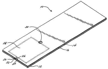
Referring now to FIGS. 1 and 2, the article 10 comprises a base layer 12,
overiying the base layer 12 a core layer 14, and overiying the core layer 14 a
cover
layer 16. The core layer 14 has a first major surface 17 and a second major
surface 18.
The core layer 14 comprises an application site 20 communicating with a first
end 22 of
7
CA 02334269 2000-12-05
WO 99/64620 PCT/US99/12294
a flow channel 24. The flow channel 24 has a second end 26, which communicates
with an optical reading chamber 28. The cover layer 16 has an opening 30,
which
serves as a vent. This embodiment requires a base layer 12 below the core
layer 14,
because the optical reading chamber 28 extends all the way through the core
layer 14.
A first major surface 38 of the cover layer 16 is in face-to-face contact with
major
surface 17 of the core layer 14. A first major surface 40 of the base layer 12
is in face-
to-face contact with major surface 18 of the core layer 14.
Referring now to FIGS. 3, 4, 5, 6, and 7, the article 100 comprises a base
layer
102, overlying the base layer 102 a core layer 112, and overlying the core
layer 112 a
cover layer 114. The core layer 112 has a first major surface 116 and a second
major
surface 118. The core layer 112 comprises an application site 120
communicating with
a first end 122 of a flow channel 124. The flow channel 124 has a second end
126,
which communicates with an optical reading chamber 128. The cover layer 114
has an
opening 130, which serves as a vent. A vent channel 132 having a first end 134
that
communicates with the optical reading chamber 128 and a second end 136 that
communicates with the opening 130 is provided in the core layer 112. This
embodiment requires a base layer 102 below the core layer 112, because the
optical
reading chamber 128 extends all the way through the core layer 112. A first
major
surface 138 of the cover layer 114 is in face-to-face contact with major
surface 116 of
the core layer 112. A first major surface 140 of the base layer 102 is in face-
to-face
contact with major surface 118 of the core layer 112.
Referring now to FIGS. 8 and 9, the article 210 comprises a base layer 212
having a first major surface 214 and a second major surface 216. Overiying the
base
layer 212 and in face-to-face contact with major surface 214 is a cover layer
218. The
base layer 212 comprises an application site 220 communicating with a first
end 222 of
a flow channel 224. The flow channel 224 has a second end 226, which
communicates
with an optical reading chamber 228. The cover layer 218 has an opening 230,
which
serves as a vent. A vent channel 232 having a first end 234 that communicates
with
the optical reading chamber 228 and a second end 236 that communicates with
the
opening 230 is provided in the base layer 212. This embodiment does not
require a
third layer in face-to-face contact with major surface 216 of the base layer
212 because
the application site 220, the flow channel 224, and the optical reading
chamber 228 are
elevated from major surface 16 of the base layer 212. The embodiment shown in
FIGS.
3, 4, 5, 6, and 7 is preferred because it is easier to prepare in mass
quantities.
Regardless of which embodiment is used, the surface dimensions of each layer
are not critical, except to the extent that the dimensions must be selected so
that the
8
CA 02334269 2000-12-05
WO 99/64620 PCT/US99/12294
article will properiy fit into an optical metering device. An example of
surface
dimensions suitable for an article of this invention having a rectangular
surface are a
length of 30 mm and a width of 20 mm. With respect to the preferred
embodiment, an
example of the thickness of the article is 0.3 mm. An example of the thickness
of the
base layer 102 is 0.1 mm. An example of the thickness of the cover layer 114
is 0.1
mm. An example of the thickness of the core layer 112 is 0.3 mm.
The portion of the cover layer and the portion of the base layer in register
with
the top and bottom of the optical reading chamber should be capable of
transmitting
light so that light transmitted through the article will not be obstructed
from the reaction
product. In the embodiment employing a core layer, the core layer need not be
capable
of transmitting light.
At least one of the base layer and cover layer must be hydrophilic. The core
layer must not be capable of absorbing liquid. Materials that are suitable for
preparing
the core layer include glass and polymeric materials.
It should be noted that each of the named layers, i. e., the base layer, the
core
layer, and the cover layer, can comprise a single layer of material or, in the
altemative,
two or more layers of material joined together, as by adhesive, heat sealing,
or some
other means of lamination. However, it is preferred that each of the layers
comprise a
single layer of material on account of cost considerations, unless a composite
layer
would provide improved performance with respect to some parameter.
The optical reading chamber is capable of serving three functions: sample
metering, reagent storing, and optical measurement. The volume of the optical
reading
chamber should be sufficiently large so that accurate optical measurement of
concentration of analyte can be made. The volume of the optical reading
chamber
should be sufficiently small so that the volume of sample required for
measurement can
be extremely small. It is preferred that the volume of the optical reading
chamber be
less than about 1.0 pL, so that a small volume of sample will be sufficient.
The shape of
the optical reading chamber is not critical. However, it is preferred that the
optical
reading chamber be cylindrical in shape to bring about improved flow
properties and
reduction in the amount of sample required. Other shapes, e. g., rectangular,
of the
optical reading chamber can be used. It is preferred that the read area of the
optical
reading chamber be of a shape similar to the area of the light source. For
example, if
the light source is circular in shape, it is preferred that the optical
reading chamber be
cylindrical in shape. It is preferred that the depth of the optical reading
chamber be
selected so that the amount of sample required can be minimized.
9
CA 02334269 2000-12-05
WO 99J64620 PCT/US99/12294
The flow channel preferably has a rectangular cross-section, primarily because
of ease of manufacture. The cross-section of the flow channel should be of a
sufficient
size so that a sufficient quantity of fluid can flow at a sufficient rate of
flow even if
random manufacturing defects are present in the flow channel. It is preferred
that the
dimensions of the cross-section of the flow channel be selected so that the
depth of the
flow channel is substantially equal to the depth of the optical reading
chamber. If the
depth of the flow channel is substantially greater than the depth of the
optical reading
chamber, a greater volume of sample may be required to carry out an assay. If
the
depth of the flow channel is substantially smaller than the depth of the
optical reading
chamber, manufacturing defects should significantly reduce the rate of flow of
the
sample. The width of the flow channel is selected so that the amount of sample
required can be minimized. The length of the flow channel is selected so that
the
amount of sample required can be minimized. Other factors to be considered in
selecting the dimensions of the flow channel include manufacturing problems
and
likelihood of evaporation of sample.
The vent channel preferably has a rectangular cross-section, primarily because
of ease of manufacture. The vent channel should be of a sufficient length that
evaporation of the sample in the vent channel does not adversely affect the
optical
reading chamber. An example of such an adverse effect is the presence of an
air
bubble in the optical reading chamber, which will result in erroneous
absorbance
readings. The volume of the vent channel is preferably made as small as
possible in
order to reduce the volume of the sample. The volume of the vent channel
should be
sufficiently great that air bubbles will not be formed in the optical reading
chamber. The
depth of the vent channel and the width of the vent channel are selected so
that air
bubbles will not be formed in the optical reading chamber.
Representative examples of dimensions of other features of the article of the
preferred embodiment (FIGS. 3, 4, 5, 6, and 7) are as follows:
ea ure Dimensions
p ica reading c am er 1.5 mm diameter x mm depth
Flow c anne mm length x 0.5 mm width 0.1 mm
depth
Vent c anne mm length x 0.5 mm width x 0.1 mm
depth
Vent opening 0.05 mm diameter
CA 02334269 2000-12-05
WO 9~/64620 PCT/US99/12294
Detection of analyte is carried out by measuring the change in an optical
property of the material in the optical reading chamber resulting from one or
more
reactions involving the analyte with one or more reagents, whereby changes in
absorbance can be observed by an optical instrument. In the case of
determination of
glucose, the reagents typically include at least one enzyme and at least one
dye.
In one assay system for determining concentration of glucose, glucose in the
sample is oxidized by glucose oxidase to form gluconic acid and H202. The
amount of
H202 produced is then measured quantitatively by Reaction (1) or Reaction (2).
Reaction (1)
Peroxidase
Dye (coloriess) + H202 >Oxidized dye (colored) + H20
Reaction (2)
H202 + Fe2+ > Fe3' + H20
Fe3' + dye > Fe3* dye complex
In Reaction (1), the enzyme peroxidase (e. g., horse radish peroxidase,
microperoxidase) catalyzes the oxidation of the dye or converts H202 to H20.
The color
intensity is directly proportional to the concentration of glucose in the
sample.
Representative examples of dyes that have been used include o-dianisidine, 4-
aminoantipyrine, and 3,5-dichloro-2-hydroxybenzenesulfonate.
In Reaction (2), H202 oxidizes the Fe2+ to Fe3'. Fe3'then chelates with dye to
produce a specific absorption peak. Representative examples of ferrous salt
include
ferrous sulfate and potassium ferrocyanide. Representative examples of the dye
include xylenol orange. The amount of Fe3+ dye complex that forms is
proportional to
the amount of glucose in the sample.
In another assay system for determining concentration of glucose, which is
preferred for this invention, glucose dehydrogenase enzyme reacts specifically
with
glucose in the sample in the presence of co-enzyme 0-nicotinamide adenine
dinucleotide (0-NAD) to form NADH, the reduced form of + R-NAD. The NADH
reacts
with an electron accepting dye, e. g., 3-[4,5-dimethylthiazol-2-yl]-2,5-
diphenyltetrazoiium bromide (MTT), catalyzed by the diaphorase enzyme to form
a dark
11
CA 02334269 2007-08-28
purple-reddish color. The color intensity measured at 640 nm is directly
proportional to
the concentration of glucose in the sample.
Glucose dehydrogenase
Glucose +(3-NAD Gluconic acid + NADH
Diaphorase
NADH + MTT (yellow) ---~ MTT (purple-reddish) + P-NAD
In both systems, detection is carried out by means of optical measurement. The
measurement can be of absorbance, reflectance, or transmittance. It is
preferred that
absorbance be employed. The specimens suitable for the method include, but are
not'
limited to, blood, plasma, serum, interstitial fluid, urine.
Operation
Samples of interstitial fluid can be obtained from a patient by any of a
variety of
methods, which are well-known to one of ordinary skill in the art. Such
methods
include, but are not limited to, those described in U. S. Patent Nos.
4,775,361;
5,423,803; WO 94/09713; and WO 97/07734.
The multiple-layer element preferably contains a dried reagent in the optical
reading chamber 128. The sample obtained from the patient is introduced to the
multiple-layer element at the application site 120. After introduction to the
element, the
liquid sample flows through the flow channel 124 into the optical reading
chamber 128
and from the optical reading chamber 128 to the end of the vent channel 132.
The fluid
ceases flowing when it reaches the opening 130. The liquid sample rehydrates
the
dried reagent in the optical reading chamber, which then reacts with the
analyte of
interest. The reaction occurs in the optical reading chamber. The flow through
flow
channel 124 can be characterized as capillary flow, i. e., flow that is driven
by capillary
attraction, which can be defined as the force that results from greater
adhesion of a
liquid to a solid surface than internal cohesion of the liquid itself.
Altematively, if the
multiple-layer element does not contain a dried reagent in the optical reading
chamber,
12
CA 02334269 2000-12-05
WO 99/64620 PCT/US99/12294
the sample obtained from the patient can be mixed with the reagent, and the
resulting
mixture introduced to the multiple-layer element at the application site 120.
After
introduction to the element, the reaction mixture flows through the flow
channel 124, by
means of capillary flow into the optical reading chamber 128 and from the
optical
reading chamber 128 to the end of the vent channel 132. The reaction mixture
ceases
flowing when it reaches the opening 130. The reaction occurs prior to the
entrance of
the reaction mixture to the optical reading chamber.
Regardless of how the sample and the reagents are introduced into the article,
the optical readings are taken when the reaction product, i. e., the product
of reaction
between the reagent and the analyte, is finally located in the optical reading
chamber.
The optical reading is typically an absorbance reading. FIG. 16 shows an
apparatus
suitable for measuring absorbance. The apparatus 300 comprises a source of
light 302
and a detector 304. The multiple-layer element 306 is disposed between the
source of
light 302 and the detector 304. The optical reading chamber 308 in the
multiple-layer
element 304 is aligned with the light from the source of light 302 and the
detector 304
so that the light from the source of light 302 is transmitted through the
optical reading
chamber 308 and detected by the detector 304. The source of light 302
preferably has
a wavelength of from about 500 nm to about 700 nm. A preferred source of light
is a
light emitting diode. The detector 304 is preferably a photodetector, and the
readings
are usually reported in volts.
The element of the present invention provides several significant advantages.
First, only a very low volume of sample is required for carrying out the
assay. Second,
the fluid transfer does not require precision pipetting. In addition, the
results of the
assay can be read optically. Optical reading can provide more accurate results
than
can results read electronically. Furthermore, the article can be constructed
so that
evaporation of the sample can be minimized. The particular reagents that are
used in
the article and method of this invention are capable of reacting under low
oxygen
conditions, with the result that the results are accurate, sensitive, and
reproducible.
The utilization of capillary flow for filling the optical reading chamber
allows the
elimination of the need for extemal force to fill the optical reading chamber,
thereby
eliminating the need for pumps, motors, tubing, and the like.
The article and method of this invention can be adapted for measuring the
concentration of analytes other than glucose. Such analytes include, for
example,
cholesterol, uric acid, BUN (blood urea nitrogen), and creatinine.
The following non-limiting examples are intended to further illustrate the
invention.
13
CA 02334269 2000-12-05
WO 99/64620 PCT/US99/12294
EXAMPLES
EXAMPLE 1
This example demonstrates the feasibility of a glucose assay wherein the
sample
size was less than 25 uL.
The following materiais were purchased from Sigma Chemical Company:
Glucose oxidase
Horseradish peroxidase
4-Aminoantipyrine
3, 5-Dichloro-2-hydroxy-benzenesulfonic acid
Sodium phosphate
Glucose was purchased from EM Sciences.
The absorbance of the reaction product was read at 515 nm in a Hewlett Packard
Diode Array Spectrophotometer (model 8452A). The multiple-layer elements 400
used
in this example were of the type depicted in FIGS. 1 and 2. The element shown
in
FIGS. 1 and 2 is substantially similar to that shown in FIGS. 3, 4, 5, 6, and
7 with the
exceptions that the optical reading chamber has a different size and a
different
geometric shape. The core layer 14 of the multiple-layer element 10 was 0.33
mm
thick. The cover layer 16 and the base layer 12 of the multiple-layer element
400 were
0.11 mm thick. The cover layer 16 and the base layer 12 were adhered to
opposite
major surfaces of the core layer 14 by means of adhesive. The cover layer 16
and the
base layer 12 of the multiple-layer element 10 were made of polycarbonate. The
core
layer 14 of the multiple-layer element 10 was made of polyester. The
dimensions of the
surface of the element were 10 mm wide by 30 mm long. The dimensions of the
optical
reading chamber 28 were 7.7 mm x 9.6 mm x 0.33 mm. The volume of the optical
reading chamber 28 was about 24.4 pL.
The reagents used in the assay were prepared as follows:
Buffer: 50 mM phosphate, pH 7.0
14
CA 02334269 2000-12-05
WO 99/64620 PCT/US99/12294
Enzyme solution: horseradish peroxidase (2 units/NL) and glucose
oxidase (2 units/NL) were dissolved in 50 mM
phosphate, pH 7.0 (stock solution)
Dye solution: a mixture of 0.5 M of 4-aminoantipyrine and 0.5 M 3,
5-dichloro-2-hydroxy-benzenesulfonate in 50 mM
phosphate buffer, pH 7.0 (stock solution)
Glucose solution: glucose solutions contained 0, 31.1, 62.2, 125, 250
mg/dL prepared in 50 mM phosphate buffer, pH 7.0
To glucose solution (1.0 mL) was added enzyme solution (20 pL) and dye
solution (50
pL). The reaction was carried out at room temperature for two minutes. The
reaction
mixture was then drawn into the optical reading chamber by capillary
attraction and the
absorbance of the reaction mixture read at 515 nm. The following table shows
the
absorbance of the reaction mixture at various concentrations of glucose.
TABLE 1
Concentration of glucose Absorbance
(mg/dL)
0 0.09
31.1 0.34
62.2 0.71
125.0 1.38
250.0 2.39
FIG. 10 illustrates the dose response curve for this example. From the data in
TABLE 1
and the dose response curve, it can be seen that the article and method of
this example
provide a linear response. A linear dose response is preferred because such a
response simplifies calculation of concentration of analyte.
CA 02334269 2000-12-05
WO 99/64620 PCT/US99/12294
EXAMPE-E 2
This example demonstrates the feasibility of a glucose assay utilizing a small
volume of sample.
The following materials were purchased from Sigma Chemical Company.
Tris (hydroxymethyl) aminomethane buffer (hereinafter'Tris buffer")
MgC12 = 6H2O
Adenosine 5'-triphosphate (ATP)
[i-Nicotinamide adenine dinucleotide (0-NAD)
3-[4,5-dimethylthiazol-2-yl]-2,5-diphenyltetrazolium bromide (MTT)
Hexokinase
Glucose 6-phosphate dehydrogenase (G-6-PDH)
Diaphorase
Glucose was purchased from EM Sciences.
The following compounds were weighed and dissolved in 1.3 mL of 0.2 M Tris
buffer, pH 7.0:
MgCI2 = 6H2O 0.0276 g
ATP 0.0165 g
R-NAD 0.0189 g
MTT 0.030 g
Hexokinase 75 units
G-6-PDH 75 units
Diaphorase 75 units
The reagent was prepared in the following manner. The MTT was first dissolved
in the
Tris buffer. R-NAD and ATP were then added to the solution and dissolved. The
pH of
the resulting solution was then readjusted to 7.0 by means of a 1.0 M Tris
solution. The
remaining components were then added and the resulting mixture was mixed.
The multiple-layer element used in this example was of the type shown in FIGS.
3, 4, 5, 6, and 7. The features of the multiple-layer element had the
following
dimensions:
16
CA 02334269 2000-12-05
WO 99164620 PCT/US99/12294
TABLE 2
Feature Dimensions
Optical reading chamber 1.5 mm diameter x 0.3 mm depth
Flow channel 0.5 mm x 1.0 mm x 0.3 mm depth
Vent channel 0.5 mm x 0.5 mm x 0.3 mm depth
Vent opening 0.05 mm diameter
Cover la er 12 mm x 30 mm x 0.1 mm
Base la er 12 mm x 30 mm x 0.1 mm
Core layer 12 mm x 30 mm x 0.3 mm
Reagent (0.3 NL) was introduced into the multiple-layer element at the
application site by means of capillary attraction. Glucose solution (0.3 pL,
250 mg/dL)
was then introduced into the multiple-layer element at the application site by
means of
capillary attraction. The final reaction volume was 0.582 pL. The rate of
reaction was
monitored in a Hewlett Packard Diode Array Spectrophotometer (model 8452A) at
640
nm. The reaction was complete in about two minutes at room temperature. FIG.
11
illustrates absorbance as a function of time. It can be seen that the rate of
change in
absorbance as a function of time decreases after about 15 seconds.
EXAMPLE 3
This example demonstrates the nature of dose response of a glucose assay
utilizing a multiple-layer element having the same dimensions as the element
described
in Example 2. The reagent employed was the same as that described in Example
2.
The result of each reaction was read after two minutes. Standard glucose
solutions were used. A linear glucose response curve was obtained.
FIG. 12 illustrates absorbance at 640 nm as a function of glucose
concentration.
From FIG. 12, it can be seen that the article and method of this example
provide a
linear dose response.
17
CA 02334269 2000-12-05
WO 99/64620 PCT/US99/12294
EXAMPLE 4
This example demonstrates a glucose assay utilizing a small volume of sample
and a volume of optical reading chamber of 0.251 NL.
The materials and multiple-layer element of the type described in Example 2
were employed. The dimensions of the optical reading chamber were 1.5 mm
diameter, 0.10 mm depth. The flow channel and the vent channel were 0.5 mm in
width, 0.5 mm in length, and 0.1 mm in depth.
Reagent (10 pL) (from Example 2) was mixed with glucose solution (10 NL). The
resulting mixture was introduced into the element at the sample application
site by
means of capillary attraction. Absorbance readings at 640 nm were taken after
two
minutes. Sufficient runs were carried out to prepare a dose response curve.
A linear glucose dose response curve was obtained. The curve is described by
the formula y= 3.003x + 179.24; r2 = 0.9887. The hexokinase/G-6-
PDH/Diaphorase/MTT system gave a detection sensitivity of about 3 mA/mg/dL of
glucose. The reproducibility of the multiple-layer element was tested by
reading the
absorbance of the reaction mixture of the same glucose solution in six
different
elements. As can be seen from TABLE 3, CV of 7.02 was obtained at about 173
mg/dL
of glucose.
ZABL.E3
Run no. Concentration of glucose
(mg/dL)
1 187
2 170
3 164
4 164
5 164
6 190
Mean =173
S.D.12.14
CV% = 7.02
18
CA 02334269 2000-12-05
WO 99/64620 PCT/US99/12294
FIG. 13 illustrates that a linear dose response was obtained. From the data of
this
example, it can be seen that there was low variation from sample to sample.
EXAMPLE 5
This example demonstrates a glucose assay utilizing a small volume of sample
and multiple-layer elements containing reagent in a dried state. Elements of
the type
described in Example 2 were used. However, in each element, only the base
iayer had
been laminated to one major surface of the core layer. The other major surface
of the
core layer had been left uncovered so that reagent could be deposited into the
optical
reading chamber.
The reagent was prepared as described in Example 2. Reagent (0.5 uL) was
transferred by pipette into the optical reading chamber of each multiple-layer
element.
The reagent was allowed to dry at room temperature. The remaining major
surface of
the core layer was then laminated to one major surface of the cover layer. The
cover
layer contained a small opening for vent. The thus-formed multiple-layer
eiements were
then stored in a container containing silica.
In order to conduct the assay, the glucose solution was introduced into the
multiple-layer element at the application site by means of capillary
attraction. The
volume of each sample was 0.25 NL. When the fluid reached the vent opening,
the flow
of fluid ceased. The results of the reaction were read at 640 nm at room
temperature
after one minute. Sufficient runs were carried out to prepare a dose response
curve.
FIG. 14 illustrates current (the absorbance signal) as a function of glucose
concentration. The data in FIG. 14 shows that the article and method of this
example
provide a linear dose response.
EXAMPLE 6
This example demonstrates the feasibility of a glucose assay utilizing a small
volume of sample with an enzyme system comprising glucose dehydrogenase and
diaphorase.
The following materials were purchased from Sigma Chemical Company:
Tris buffer
MgCI2 - 6H20
R-Nicotinamide adenine dinucleotide (R-NAD)
19
CA 02334269 2000-12-05
WO 92/64620 PCT/US99/12294
3-[4,5-dimethylthiazol-2-yl]-2,5-diphenyitetrazolium bromide (MTT)
Glucose dehydrogenase
Diaphorase
Glucose was obtained from EM Sciences.
The enzyme system was prepared in the following manner. MTT (3 mg) was
dissolved in 100 mM Tris buffer (200 pL), pH 7Ø [3-NAD (12 mg) was then
added to
the solution and allowed to dissolve. To this mixture was added 1.0 M MgC12 =
6H2O (2
pL). The pH of the solution was adjusted to 7.0 by means of 1.0 M Tris buffer.
To this
mixture was then added glucose dehydrogenase (5 mg, 75 units/mg) and 15 units
of
diaphorase.
The reagent (3 NL) mixed with glucose solution (3pL) was introduced by means
of capillary attraction into an element of the type described in Example 2.
The
absorbance of the reaction product was measured at 650 nm using the instrument
shown in FIG. 16. Sufficient runs were carried out to prepare a dose response
curve.
FIG. 15 shows a linear glucose dose response up to 500 mg/dl with a detection
sensitivity of 35 mg/dL.
Various modifications and alterations of this invention will become apparent
to
those skilled in the art without departing from the scope and spirit of this
invention, and
it should be understood that this invention is not to be unduly limited to the
illustrative
embodiments set forth herein.