Note: Descriptions are shown in the official language in which they were submitted.
CA 02334588 2000-12-07
WO 99/64090 PCT/US99/12852
PATIENT-CONTROLLED DRUG ADMINISTRATION DEVICE
BACKGROUND OF THE INVENTION
s The present invention relates to the field of patient-controlled drug
administration devices. More specifically, it relates to an apparatus for
administering a medicinal agent to a patient that allows the patient to
provide a
precisely controlled self administered bolus dose of the agent in addition to
a
continuous flow of the agent.
~o In many clinical situations, it is necessary to administer a continuous
flow of a medicinal agent to a patient, and to augment the basal flow
periodically or intermittently with a supplemental or "bolus" dose of the
agent.
This regimen is frequently used in the management of chronic pain, where a
continuous flow of an analgesic is maintained by infusion, but a bolus dose of
~s the analgesic is infused at selected times when the patient experiences a
sharp
increase in the pain. Because most analgesics must be carefully administered
to avoid overdosing, the timing and the volume of the bolus doses must be
carefully controlled. This control is often exercised by a medical
practitioner
who administers the bolus dose when it is deemed necessary or desirable.
zo In chronic care situations, or in home care situations, it is impractical,
in many cases, to have a medical practitioner available whenever a patient
wants or needs a supplemental bolus dose. Consequently, a number of drug
administration devices have been developed that allow the patient to self
administer a controlled bolus dose. These devices (sometimes called patient-
Zs controlled administration devices, or "PCA" devices) typically provide a
bolus
.. ..
21-96-2b00 ~ 02:34588 2000-12-07 US 009912852
.. ~ ~ . . .
24235PC1 , .. ~ . , . . , .
. ..
.. ~. ~ . , ~ ~~~ ~ ~ , ~
. . ~ ' ~.. ~~ ~ ~~ ~.
,.
.... ...
2
dose that is no more than a predetermined volume, and they also typically
include
a "lock-out" mechanism, by which is meant a mechanism that limits the
frequency
of bolus dose administration, or that limits the total bolus dose volume
administered
over a selected time interval. Some, but not all, prior art PCA devices also
allow a
controlled continuous flow of the agent between bolus doses. Examples of prior
art
PCA devices are disclosed in the following U.S. patents: 4,398,908 - Siposs;
4,544,371 - Dormandy, Jr. et al.; 4,548,607 - Harris; 4,601,707 - Albisser et
al.;
4,634,427 - Hannula et al.; 4,668,231 - de Vries et al.; 4,699,615 - Fischell
et al.;
4,828,551 - Gertler et al.; 4,898,584 - Borsanyi et al.; 4,898,585 - Borsanyi
et al.;
5,011,477 - Winchell et al.; 5,061,243 - Wincheil et al.; and 5,304,153 -
Tsujikawa.
Many of the prior art PCA devices are specifically designed to be
implantable within the patient's body. For example, of the above-listed
patents, the
following disclose implantable devices: Dormandy, Jr. et al. '371, Harris
'607,
Hannula et al. '427, de Vries et al. '231, Fischefl et al. '615, Borsanyi et
al. '584,
and Borsanyi et al. '585. This approach, which requires a surgical procedure
for
the implantation, may not be suitable for all patients, especially those whose
need
for the drug is temporary, even if relatively long-term.
Many of the non-implantable PCA devices that have been developed to
date are bulky or complex. Such devices are typically expensive to
manufacture,
and therefore not suitable for single-patient disposable applications. Other
devices, while providing convenient delivery of bolus doses on patient demand,
require a parallel system for delivery of a continuous flow. An example of the
latter
type of device is disclosed in U.S. Patent No. 5,304,153 - Tsujikawa.
EP-A-0 523 456, which corresponds to the above mentioned US Patent No.
5,304,153, discloses a device for self-dosing a liquid medicine and comprising
a
casing having a chamber for receiving the liquid medicine to be self-dosed by
a
AMENDED SHEET
21-06-2000 ~ 02334588 2000-12-07
~ ..
. 2,423bPC1 » ~ ~ ~ ~' " US 009912852
.. ~ , .. " .
:. ~~ ~ ' " ~ ~ ~~'
. . . . : . . .. . . ..
~ ~ ~ ~ ~ ' .. ..
. . ~ ~ .. ~~
.... ...
3
patient. The chamber has inlet and outlet ports communicating with the
chamber,
and a piston is fitted liquid-tightly in the chamber. A push button is
attached to the
actuating piston and is capable of being pressed by the patient a desired
number
of times corresponding to an amount of dosed liquid medicine, and a spring
urging
the piston towards the home position. With the patient's hand being removed
from
the button the spring forces the piston backwards to its home position and a
resulting negative pressure causes a subsequent smooth refilling of the
chamber.
The device described may be combined with an apparatus having a usual dosing
line through which the liquid medicine flows continuously at a iow flow rate.
Thus, there has been a need for a non-implantable PCA device that
provides convenient, measured, patient-controlled bolus doses of a therapeutic
agent, and that also allows for a regulated continuous or basal flow of the
agent.
Furthermore, it would be advantageous if such a device were to have a "lock-
out"
mechanism that limits the total bolus dose volume delivered at any one time or
over any specified time interval. In addition, it would be advantageous for
such a
device to be simply constructed and easily and inexpensively manufactured, so
that it may be made as a single-patient disposable apparatus.
SUMMARY OF THE INVENTION
The present invention provides a device for the administration of a liquid
therapeutic agent to a patient, said device being of the type comprising a
fluid flow
conduit having an upstream portion and a downstream portion, which are in
liquid
communication via first and second conduit sections connected in parallel, a
check
valve in fluid communication with the second conduit section that is
responsive to a
predetermined cracking pressure to allow fluid flow from the second conduit
section
AMENDED SHEET
21-06-2b00 ~ 02334588 2000-12-07
24235PC1 ' ~ " US 009912852
.. . .. ~.. , . .
:. .: ~ ~ ~' ; : ...
~ ~ . ..
. . . ~~ , ~ . .~ ~ ,.
~ : ~ ~ '..' ~~~~ ~ ~~ ..
- ~ .... ...
3a
to the downstream portion, and a bolus dose delivery mechanism that is
selectively
actuate able to apply a pressure that is at least equal to the cracking
pressure to
express a predetermined volume of the agent through the second conduit section
and the check valve. The device according to the invention is characterised in
that
the fluid flow conduit is defined in a housing, which also defines a chamber
therein
having an inlet lumen in fluid communication with said upstream portion and
first
and second outlet lumens constituting said conduit sections and being
separately
in communication with the downstream portion, and in that the bolus dose
delivery
mechanism is selectively actuate able to (a) apply said pressure at least
equal to
the cracking pressure to the chamber so as to express said volume there from
through the second outlet lumen, and (b) allow a refilling of the chamber with
the
agent through the first inlet lumen while also allowing a continuous flow of
the
agent from the chamber through the first outlet lumen. Continuous flow is
provided
through the first flow-restricting orifice, the chamber, and the second flow-
restrictive
orifice, the continuous flow serving to fill the chamber at a controlled rate
through
the first flow-restrictive orifice. The bolus dose delivery mechanism is
manually
actuable to express the contents of the chamber through the check valve to
supplement the continuous flow through the downstream portion.
In a particular preferred embodiment, the bolus dose delivery mechanism
comprises a resilient diaphragm that forms a sealed closure for the chamber.
The
diaphragm is movable from a decompressed position to a compressed position by
a plunger that is in direct engagement with the exterior surface of the
diaphragm,
and it is restored to the decompressed position by the flow of fluid into the
chamber.
AMENDED SHEET
CA 02334588 2000-12-07
WO 99/64090 PCT/US99/12852
4
In operation, a liquid therapeutic agent is continuously delivered, under
pressure, to the chamber through the upstream portion at a flow rate
controlled
by the first flow-restricting orifice. The agent fills the chamber against the
resistance offered by the diaphragm, the fluid flow pushing the diaphragm
s from its compressed to its decompressed position as the chamber fills. A
fractional portion of the agent that flows into the chamber also flows out of
the
chamber, throughout the filling process, through the second flow-restricting
orifice. All of the outflow is through the second flow-restricting orifice,
the
pressure of the flow being less than the cracking pressure of the check valve.
~o When the chamber is filled to capacity, after a predetermined time
interval, the
diaphragm is in its fully decompressed position, in which it offers little or
no
resistance to the fluid flow into the chamber. With the chamber filled, the
continuous flow rate through the device achieves a predetermined steady state,
regulated by the first and second flow-restricting orifices.
is When a bolus dose is desired, the plunger is depressed to push the
diaphragm toward its compressed position. This compression of the volume of
the chamber pressurizes its contents to a pressure above the cracking pressure
of the check valve, thereby opening the check valve so that the contents of
the
chamber are expressed through the check valve. Because the open check
2o valve offers less flow resistance that the second flow-restricting orifice
that is
in parallel with it, substantially all of the outflow from the chamber is
through
the check valve, rather than the second flow-restricting orifice.
After the bolus dose is thus delivered, the chamber is refilled, as
described above, by the continuous flow of the agent. Because a
25 predetermined time interval must elapse before the chamber is completely
refilled and ready to deliver another bolus dose on demand, the maximum
volume of the total bolus dose deliverable over any given period of time is
defined by a predetermined limit. Thus, the above-described lock-out function
CA 02334588 2000-12-07
WO 99/64090 PCT/US99/12852
S
is thereby provided.
As will be more fully appreciated from the detailed description that
follows, the subject invention provides both a controlled continuous (basal)
flow and a controlled bolus dose on demand. The total volume of the bolus
s dose deliverable over a given period of time is, however, limited to a
predetermined maximum by the above-described lack-out function. These
capabilities are achieved in device that may be made small enough and light
enough in weight to be comfortably worn (e.g., on the wrist) by a patient.
Furthermore, a PCA device in accordance with the present invention is simple
~o in construction, and may therefore be manufactured inexpensively, so as to
be
adapted for single patient, disposable use. Such simplicity also lends itself
to
reliability and ease of maintenance and care.
BRIEF DESCRIPTION OF THE DRAWINGS
Figure 1 is a semi-schematic view of a drug infusion system employing
a patient-controlled administration (PCA) device in accordance with a
preferred embodiment of the present invention;
Figure 2 is a longitudinal cross-sectional view of a PCA device in
accordance with a preferred embodiment of the present invention, taken along
20 line 2 - 2 of Figure 1, showing the diaphragm of the bolus dose delivery
mechanism in its compressed position;
Figure 3 is an enlarged detailed view of the check valve of the PCA
device of Figure 2, as encompassed within the broken outline 3 of Figure 2;
Figure 4 is a cross-sectional view, similar to Figure 2, but showing the
2s diaphragm of the bolus dose delivery mechanism in its decompressed
position;
and
Figure 5 is a cross-sectional view taken along line 5 - 5 of Figure 4.
CA 02334588 2000-12-07
WO 99/64090 PCT/US99/12852
6
DETAILED DESCRIPTION OF A PREFERRED EMBODIMENT
Referring now to the drawings, Figure 1 shows a drug infusion system
employing a patient-controlled administration (PCA) device 12 in
accordance with a preferred embodiment of the present invention. The system
s comprises a pressurized fluid source 14 that holds a supply of a liquid
therapeutic agent, and that pumps the agent into the PCA device 12 through a
supply conduit 18 under a predetermined pressure. The supply conduit 18 is
fluidly connected to the upstream side of the PCA device 12, as will be
described below. The downstream side of the PCA device 12 is fluidly
io connected to a delivery tube 20, as described below, which terminates in a
needle (not shown), which may be configured for intravenous, subcutaneous,
intramuscular, or intrathecal injection.
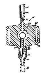
Figures 2 through 5 illustrate the PCA device 12 in detail. The device
12 comprises a housing 22 defining a fluid conduit having an upstream portion
~ s 24 and a downstream portion 26. The upstream portion 24 is fluidly
connectable to the supply conduit 18, while the downstream portion 26 is
fluidly connectable to the delivery conduit 20. The fluid conduit of the PCA
device 12 includes a chamber 28 having an inlet part 30 in fluid
communication with the upstream portion 24 and first and second outlet ports
32, 34 in fluid communication with the downstream portion 26. In a specific
preferred embodiment of the invention, the chamber 28 has a maximum
volume of about 0.5 ml when filled. A first or upstream flow-restricting
orifice 36 is contained within the upstream portion 24, and a second or
downstream flow-restricting orifice 38 is contained within the first outlet
port
32 at the juncture with the downstream portion 26.
The PCA device 12 includes a bolus dose delivery mechanism, which is
best described with reference to Figure 4. The bolus dose delivery mechanism
includes the chamber 28, which is enclosed by the housing 22 on all sides
CA 02334588 2000-12-07
WO 99/64090 PCT/US99/12852
7
except for one side that is sealed by a resilient diaphragm 40. The diaphragm
40 has a raised central portion 42 that is directly engaged by the inner end
of a
plunger 44 that is axially movable within a cylindrical fitting 46. The
diaphragm 40 also has a peripheral bead 48 that seats in a conforming circular
s groove 50 in the housing 22. A peripheral skirt 51 is provided
circumferentially around the distal (inner) end of the cylindrical fitting 46.
The skirt 51 defines an annular slot 52 between itself and the distal end of
the
fitting 46. The slot 52 receives an annular lip 53 that extends proximally
(outwardly) from the housing 22, whereby the fitting 46 is attached to the
~o housing 22 and secured thereto by means such as a suitable adhesive, or by
ultrasonic welding. When the fitting 46 is thus attached to the housing 22,
the
distal (inner) end of the fitting presses the diaphragm bead 48 firmly into
the
groove 50, creating a fluid-tight seal therebetween.
The plunger 44 has a circumferential ridge S4 that is engageable against
~s the distal or interior-facing side of an annular shoulder 56 within the
cylindrical fitting 46. The engagement between the shoulder 56 and the ridge
54 limits the travel of the plunger 44 in the proximal or outward direction
within the cylindrical fitting 46 under the resilient force of the diaphragm
40.
The plunger 44 is thus captured between the diaphragm 40 and the shoulder
zo 56. The cylindrical fitting 46 has an open proximal or outer end through
which the proximal end of the plunger 44 is accessible to the finger or thumb
of the patient or other user of the device 12. Thus, the proximal end of the
plunger 44 forms a pushbutton 58 (Figure 1 ) for manual actuation of the bolus
dose delivery mechanism.
zs Situated within the second outlet port 34 is a check valve 60. As best
seen in Figure 3, the check valve 60 comprises a tubular fitting 62 tapered
toward its downstream end, which is terminated by a knob-like valve body 64.
An outlet orifice 66 is provided in the tapered portion of the tubular fitting
62
CA 02334588 2000-12-07
WO 99/64090 PCT/US99/12852
8
just upstream from the valve body 64. A conformal flexible membrane 68 is
fixed around the exterior of the tubular fitting 62, covering the outlet
orifice 66
and extending over most of the valve body 64. The membrane 68 functions
much as a "duck-bill" valve element, sealing the orifice 66 (as shown in
s Figures 2, 4, and 5) until the fluid pressure in the second outlet port 34
reaches
a predetermined "cracking pressure" that separates the membrane 68 from the
valve body 64 and thus opens the orifice 66, as shown in Figure 3.
As best shown in Figure 4, the housing 22 advantageously is formed
with a pair of laterally-extending flaps 70, each of which is provided with a
,o longitudinal slot 72. The slots 72 are configured to accommodate a wrist
strap
(not shown), allowing the device 12 to be worn on a patient's wrist (not
shown).
In operation, a liquid therapeutic agent is continuously delivered from
the pressurized fluid source 14 to the chamber 28, through the supply conduit
~s 18, to the upstream portion 24 of the PCA device 12. The liquid flows into
the
chamber 28 through the inlet 30 at a flow rate that is regulated by the first
flow-restricting orifice 36. In a specific preferred embodiment of the
invention, the flow rate through the inlet 30 is regulated to about 2.5 ml/hr.
The liquid fills the chamber 28, non-linearly versus time, against the
2o diminishing resistance offered by the diaphragm 40, the fluid flow pushing
the
diaphragm 40 from its compressed position (Figure 2) to its decompressed
position (Figure 4) as the chamber 40 fills. As the diaphragm 40 is moved
from its compressed position to its decompressed position, it pushes the
plunger 44 outwardly (in a proximal direction) within the cylindrical fitting
46.
2s The diaphragm 40 reaches its fully decompressed position when the chamber
28 is filled to capacity; at this point, the plunger 44 is pushed to its
proximal
limit of travel at which its ridge 54 abuts against the shoulder 56.
Throughout the chamber filling process, a fractional portion of the
CA 02334588 2000-12-07
WO 99/64090 PCT/US99/12852
9
liquid that flows into the chamber 28 also flows out of the chamber 28 through
the first outlet port 32, the second flow-restricting orifice 38, and the
outlet
portion 26. All of the outflow is through the first outlet port 32 and the
second
flow-restricting orifice 38, because the pressure of the flow is less than the
cracking pressure of the check valve 60. This outflow is regulated by the
second flow-restricting orifice 38 to about 0.5 ml/hr during the chamber
filling
process. Thus, with a net inflow into the chamber 28 of about 2.0 ml/hr, the
0.5 ml chamber is filled to capacity in about 15 minutes. As mentioned above,
when the chamber 28 is filled to capacity, the diaphragm 40 is at its fully
~o decompressed position. In this position, it offers little or no resistance
to the
fluid flow through the chamber 28. Consequently, once the chamber 28 is
filled, the continuous flow rate through the device increases to a steady
state
value of about 1.0 ml/hr, limited by the second flow-restricting orifice 38.
When a bolus dose is desired, the plunger 44 is pushed distally into the
~s cylindrical fitting 46 to push the diaphragm 40 toward its compressed
position.
This results in a compression of the volume of the chamber 28 that pressurizes
its contents to a pressure above the cracking pressure of the check valve 60,
thereby opening the check valve 60 so that the contents of the chamber 28 are
expressed through the check valve orifice 66. Because the open check valve
zo 60 offers less flow resistance that the second flow-restricting orifice 38
that is
in parallel with it, substantially all of the outflow from the chamber 28 is
through the second outlet port 34 and the check valve 60, rather than the
second flow-restricting orifice 38. The outflow from the check valve 60 enters
the downstream portion 26 of the fluid conduit defined by the hosing 22, and
2s then enters the delivery tube 20 as a bolus dose of the agent.
After the bolus dose is thus delivered, the chamber 28 is refilled, as
described above, by the continuous flow of the liquid agent. As described
above, the filling of the chamber 28 returns the plunger 44 to its starting
CA 02334588 2000-12-07
WO 99/64090 PCT/US99/12852
(proximal) position. Thus, no separate spring is required for the plunger's
return movement, because the plunger return function is provided by the net
effect of the pressurized fluid flow and the resistance of the diaphragm 40.
The continuous flow through the first outlet port 32 is re-established almost
s immediately after the bolus dose is delivered. Because a predetermined time
interval (e.g., approximately 1 S minutes in a specific preferred embodiment)
must elapse before the chamber 28 is completely refilled and ready to deliver
another bolus dose on demand, the maximum volume of the total bolus dose
deliverable over any given period of time is defined by a predetermined limit.
~o For example, in the specific preferred embodiment described above, the
maximum hourly bolus dose volume is 2.0 ml. Thus, the above-described
lock-out function is thereby provided to minimize the probability of over-
dosing.
It will be appreciated from the foregoing description that the PCA
~s device 12 of the present invention provides both a continuous flow and a
bolus
dose through nearly identical flow paths, the only difference being that the
continuous flow enters the downstream portion 26 through the first outlet port
32, while the bolus dose enters the downstream portion 26 through the second
outlet port 34. Thus, parallel delivery systems for the continuous flow and
the
2o bolus dose are not required.
Furthermore, as compared with prior art systems employing separate,
parallel flow paths for the bolus flow and the continuous flow (e.g., U.S.
Patent No. 5,304,153, supra), the present invention offers significant
operational advantages that reduce the likelihood of accidental overdosing.
is Specifically, if the check valve 60 and/or the downstream flow restricting
orifice 38 fails, total fluid flow through the device 12 is limited by the
upstream flow restricting orifice 36. If the upstream flow restricting orifice
36
fails, continuous fluid flow to the delivery tube 20 (and thus to the patient)
is
CA 02334588 2000-12-07
WO 99!64090 PCT/US99/12852
11
limited by the downstream flow restricting orifice ~ 8.
All of the components of the PCA device 12, except the diaphragm 40
and the check valve membrane 68, may be made of suitable injection-molded
polymeric plastics, as is conventional in the art. The diaphragm 40 and the
s check valve membrane 68 may be made from any suitable elastomeric
polymeric plastic material, as is well-known in the art. Thus, the device 12
may be made inexpensively and therefore acceptable for single-patient,
disposable use.
While a preferred embodiment of the invention has been described
~o herein, it will be appreciated that a number of modifications and
variations
may suggest themselves to those skilled in the pertinent arts. For example,
the
structure of the check valve 60 described above is exemplary only; other
equivalent check valve structures will readily suggest themselves. Also, the
structure of the diaphragm 40 may be modified without departing from the
~s scope of the invention. The fluid capacities and flow rates set forth above
are
likewise exemplary. Furthermore, the specific housing configuration
described above may be substantially varied to suit a number of different
clinical needs and patient preferences. These and other variations and
modifications that may suggest themselves are considered to be within the
2o spirit and scope of the invention, as defined in the claims that follow.