Note: Descriptions are shown in the official language in which they were submitted.
CA 02335135 2000-12-14
WO 99!66582 PCT/US99/13578
CATALYST EQUIPPED VAPOR-CO1~IUNICATING
MULTI-CELL VALVE REGULATED LEAD-ACID BATTERY
Description of the Prior Art
Lead-acid batteries are known and have achieved wide
acceptance in a variety of fields.
Valve-regulated lead-acid batteries, particularly so-
called absorbent glass mat or "AGM" valve-regulated lead-acid
batteries have achieved significant acceptance in recent years
as sources of standby electrical power. These absorbent glass
mat valve-regulated lead-acid batteries have become widely used
to provide standby power for telecommunications applications,
typically for cellular telephone towers, other telecommunications
equipment and computers. In such applications, the absorbent
glass mat valve-regulated lead-acid batteries are maintained on
a standby basis; power is drawn from these absorbent glass mat
valve-regulated lead-acid batteries only when the primary source
of power to the cellular telephone towers, other
telecommunications equipment or computer is interrupted, such as
during a failure of a public utility power grid. In such
instance, the absorbent glass mat valve-regulated lead-acid
batteries, which may have been on standby for a number of years,
supply power until the primary source of power, typically the
public utility grid, has returned to service.
Gas recombination catalysts have been used in flooded
lead-acid batteries as well as in other battery systems. These
catalysts have been positioned externally to the battery cells
contacting the open atmosphere. The catalysts recombine oxygen
and hydrogen gas on their surfaces, converting the gas back into
water vapor which condenses and flows back into the battery.
Such catalysts have found limited application in standby
batteries and have not been used heretofore for valve-regulated
lead-acid batteries due to the need for compact, space efficient
installation which is inconsistent with having an external
catalyst unit.
Valve-regulated lead-acid batteries designed for
standby service typically are electrolyte-limited, having the
entire electrolyte absorbed in microfibrous glass mat material
serving as the separator between the positive and negative
CA 02335135 2000-12-14
WO 99/66582 PCT/US99/13578
2
plates. Any water loss from the battery reduces total water
volume available and increases concentration and specific gravity
of the sulfuric acid electrolyte. Loss of liquid volume can lead
to partial loss of contact between the absorbent glass mat
separator and the active plates within the battery, resulting in
premature performance degradation.
It has been found that absorbent glass mat valve-
regulated lead-acid batteries in standby, back-up power service,
tend to lose capacity over time, even if a small trickle charge
of current is applied automatically to the battery. It has also
been found that catalysts, notably palladium, when positioned in
intimate contact with vapor phase electrolyte in an absorbent
glass mat valve-regulated lead-acid battery, tend to stem such
capacity losses by enhancing the reaction by which hydrogen and
oxygen recombine into water within the cell; it is this
recombination reaction which gives such cells their "recombinant"
name. Reduction in loss of capacity and consequent greater
confidence in the ability of such cells to provide standby power
over a long term, such as for twenty years, has been attributed
to the catalyst recombination of hydrogen and oxygen into water
and thereby reducing loss of hydrogen and oxygen gas with the
attendant loss of potential for generation of water from the
cell.
Summary of the Invention
This invention is based on the surprising and
unexpected discovery that multiple cells in a standby service
valve regulated recombinant lead-acid battery placed in vapor
communication one with another may be served by a number of
catalyst units fewer than the number of cells with excellent
performance. Such batteries exhibit substantially better gassing
rates than conventional non-catalyst equipped batteries with
conventional (non-vapor communicating) cells and have significant
manufacturing advantages.
The catalyst units are desirably associated with vent
valve housings, positioned just below the pressure relief vent.
As a result, gas trying to escape from head space via which
CA 02335135 2000-12-14
WO 99/66582 PCT/US99/13578
3
multiple cells vapor communicate one with another is in proximity
with the catalyst unit.
Surprisingly, in such batteries even in standby
service, there is sufficient mass transfer among vapor-
communicating cells that oxygen and hydrogen gas produced by the
electrolytic reaction recombine under the effect of the catalyst
even though the catalyst is not in immediate proximity with some
of the vapor-communicating cells. When batteries embodying the
invention are on float, there is a considerable decrease in gas
escaping when a catalyst is provided in a common head space,
reducing and in some cases effectively eliminating water loss.
Additionally, decreases in float current have been observed in
batteries embodying the invention vis-a-vis comparable non-
catalyst equipped commercially available batteries. Moreover,
there is an improvement in retention of electrical performance
in batteries embodying the invention vis-a-vis comparable
commercially available batteries without the catalyst. Water
vapor produced through the electrolytic reaction apparently does
not concentrate in the vicinity of the catalyst but distributes
itself throughout common head space shared by multiple vapor-
communicating cells.
In one of its aspects this invention provides a
recombinant lead-acid battery including a case, a plurality of
lead-acid cells within the case, where each cell includes a
plurality of positive and negative lead metal plates, and
absorbent separator material between at least some of the
positive and negative plates. In this aspect of the invention,
the case preferably includes partitions for separating adjacent
cells one from another with portions of the partitions being
spaced from the proximate portion of the case to define space for
mass transfer vapor migration and partial pressure equalization
among the cells within the case. At least one catalyst unit is
preferably connected to the case and communicates with the mass
transfer vapor migration and partial pressure equalization space
to enhance recombination of hydrogen and oxygen into water within
the battery.
CA 02335135 2000-12-14
WO 99/66582 PCT/US99113578
4
The catalyst unit is preferably constructed together
with a vent valve for the battery so as to be removable from the
battery unitarily with the vent valve for ease of maintenance and
manufacture. The catalyst material preferably sits in a cage
connected to a lower portion of the vent valve so that upon
insertion of the vent valve into the battery case, the catalyst
material enters the vapor communication space via which mass
transfer vapor migration and partial pressure equalization occurs
among a plurality of cells within the battery.
The catalyst unit is desirably at least partially
within the battery case and is most preferably essentially if not
totally within the battery case. The catalyst is preferably
palladium or a palladium alloy, most preferably 0.5 percent
(0.5~) palladium deposited on alumina or carbon. Other suitable
catalysts include platinum, ruthenium, rhodium, other metals of
the platinum group, precious metals, other noble metals and
compounds such as tungsten carbide. While the preferred loading
of the catalyst on the substrate is 0.5 percent (0.5~), 0.8
percent (0.8~) also works well and loadings of one percent (1~)
or less are the preferred range. However, catalyst loadings may
be as high as ten percent (10~) by weight of the substrate.
In another of its aspects, this invention provides a
recombinant lead-acid battery which includes a case and a
plurality of lead-acid cells within the case where each cell
includes positive and negative lead metal plates and absorbent
separator material between some of the positive and negative
plates. Some or all of the cells within the case are in vapor
mass transfer and partial pressure equalization communication one
with another. A plurality of catalyst units are in vapor
communication with the cells and enhance recombination of
hydrogen and oxygen into water within the battery, with the
plurality of catalyst units preferably being fewer in number than
the plurality of lead-acid cells. Preferably at least some of
the catalyst units are at least partially within the battery case
and most preferably at least some of the catalyst units are
completely within the battery case. The catalyst units are
preferably constructed to be essentially integral with a vent
CA 02335135 2000-12-14
WO 99/66582 PCT/US99/13578
valve for the battery which is removable from and replaceable in
the battery case. Most preferably, the vent valve/catalyst unit
combination fits into the top of the battery case, at a position
at which gasses evolving during the electrolytic reaction would
collect.
In yet another of its aspects, this invention provides
a method for operating a recombinant lead-acid battery having a
case, a plurality of lead-acid cells within the case, with each
cell including positive and negative lead metal plates, and
absorbent separator material between at least some of the
positive and negative plates, where the method comprises placing
at least some of the cells inta vapor communication one with
another and placing a plurality of discrete catalyst units fewer
in number than the vapor communicating cells into vapor
communication with the cells to enhance recombination of hydrogen
and oxygen into vapor phase water within the battery.
In another of its aspects, this invention provides a
pancake-style recombinant lead-acid battery having a case with
vertically stacked pluralities of lead-acid cells within the
case. Each cell preferably comprises a plurality of horizontal
positive and negative lead metal plates and absorbent separator
material between at least some of the positive and negative
plates . Pluralities of cells are in vapor communication one with
another. The battery further includes catalyst units connected
to the case and communicating with spaces via which cells of
respective pluralities vapor communicate one with another, for
enhancing combination of hydrogen and oxygen within the battery.
The number of catalyst units is preferably less than the
plurality of cells. Respective catalyst units are preferably
provided connected to the case and communicating with respective
cell vapor communication spaces on a one-to-one basis. The
pancake-style recombinant lead-acid battery manifesting aspects
of the invention may include terminals, for connecting the
battery to a load, which exit from a vertical external surface
of the case or from a horizontal external surface of the case.
In the pancake configuration, one or more common head spaces may
be provided at the top of the battery with suitable passageways
CA 02335135 2000-12-14
WO 99/66582 PCT/US99/13578
6
provided for communication therewith by the pancaked plates and
separators. In another configuration of the pancake-style
recombinant battery, the catalyst units and, optionally, a vent-
valve plug constructed integrally therewith, may be provided at
the side of the battery with suitable internal configurations
permitting vapor communication from the plates to the catalyst
unit/vent plug combinations.
The battery preferably further includes partitions
within the case for separating adjacent cells one from another
with portions of the partitions being spaced from the case to
define the cell vapor communication space.
The partitions preferably include vertical and
horizontal partitions with some of the partitions being spaced
from the case interior to define the cell vapor communication
space. The horizontal partitions may block vapor communication
between vertically stacked cells in the pancake-style recombinant
lead-acid battery manifesting aspects of the invention.
In yet another of its aspects, this invention embraces
a lead-acid battery having a case comprising a jar and a cover
and a plurality of lead-acid cells within the jar. Each cell
preferably includes a plurality of upstanding positive and
negative lead metal plates and absorbent separator materials
between at least some of the positive and negative plates. The
jar preferably includes upstanding partitions for separating
adjacent cells one from another with upper portions of the
partitions being spaced from the cover to define space for vapor
migration among cells. A catalyst unit is preferably connected
to the case and communicates with the vapor migration space to
enhance recombination of hydrogen and oxygen into water in at
least partially vapor phase within the battery.
In this aspect of the invention, plates of a given
plurality of respective cells may having upstanding terminal tab
portions extending above the upper portions of the partitions.
In such case, the battery may further include electrically
conductive members connectively extending between the terminal
tab portions of plates of like plurality of adjacent cells. The
electrically conductive members are preferably lead-metal strips
CA 02335135 2000-12-14
WO 99/66582 PCT/US99/13578
7
and are preferably welded to respective terminal tab portions.
As a variation, the jar may have upstanding partition
portions for separating adjacent cells one from another and the
cover may include downwardly extending partition portions aligned
with the upstanding partition portions to define partitions
which, with walls of the case, form compartments for the cells.
The partitions may have apertures therethrough for vapor
communication among cells in respective compartments. Upper
portions of the plates may be spaced from the cover to define
space for vapor residence. At least one catalyst unit is
preferably connected to the case and communicates with a vapor
residence space for enhancing recombination of hydrogen and
oxygen into water within the battery. The number of catalyst
units are preferably less than the plurality of cells.
In yet another variation, portions of the partitions
which are spaced from the cover may be aligned and form the upper
parts of the partitions proximate to the cover. The spaced
portions may be cutouts formed in upper parts of the partitions
proximate to the cover and may be longitudinally aligned. The
cutouts may be rectangular and may be formed in upper edges of
the partitions. The cutouts are preferably completely above the
plates of the cells but may be only partially above the plates
of the cells.
Description of the Drawings
Figure 1 is a schematic front elevation in section of
a catalyst-equipped vapor-communicating multi-cell lead-acid
vertical plate recombinant battery in accordance with the
invention.
Figure 2 is an isometric view of a jar for a catalyst-
equipped vapor-communicating mufti-cell recombinant lead-acid
battery of the type illustrated in Figure 1.
Figure 3 is a schematic front elevation of a catalyst-
equipped vapor-communicating mufti-cell lead-acid pancake style
recombinant battery having catalyst units mounted on the side of
the battery, in accordance with the invention.
CA 02335135 2000-12-14
WO 99!66582 PCTNS99/13578
8
Figure 4 is a schematic end view of the catalyst-
equipped vapor-communicating multi-cell lead-acid pancake style
recombinant battery illustrated in Figure 3.
Figure 5 is a schematic top view of a catalyst-equipped
vapor-communicating multi-cell lead-acid pancake style
recombinant battery having the catalyst unit mounted at the top
of the battery, in accordance with the invention.
Figure 6 is a schematic front elevation of the
catalyst-equipped vapor-communicating multi-cell lead-acid
pancake style recombinant battery illustrated in Figure 5.
Figure 7 is a schematic end elevation of the catalyst-
equipped vapor-communicating multi-cell lead-acid pancake style
recombinant battery illustrated in Figures 5 and 6.
Figure A is a side elevation of a battery vent valve-
catalyst carrier assembly for use in practicing the invention.
Figure B is a top view of the structure of Figure A.
Figure C is an enlarged sectional view, taken along
line C-C of Figure A of a battery vent valve-catalyst cover
assembly, together with a partial sectional view of a vent valve-
catalyst carrier assembly of a battery case.
Figure D is an inverted perspective view of the vent
valve-catalyst carrier assembly illustrated in Figures A through
C.
Figure E is a bottom view of the structure of Figure
D, with the catalyst carrier and supporting structure removed,
looking in the direction opposite that of arrows F-F in Figure
C.
Figure F is an enlarged top view of the catalyst
carrier and support structure separated from the battery vent
valve assembly of Figures A through E, looking in the direction
of arrows F-F in Figure C.
Figure G is a sectional view taken along lines G-G in
Figure F.
Figure H is an enlarged partial view of the structure
shown within dot and dash line H-H in the lower right portion of
Figure F.
CA 02335135 2000-12-14
WO 99/66582 PCT/US99/13578
9
Figure I is a side elevation of another vent valve-
catalyst carrier assembly which is a modification of the
structure illustrated in Figures A through H.
Figure J is an axial vertical section of the structure
of Figure I.
Figure K is a side elevational view of another battery
vent valve-catalyst carrier assembly for use in practicing the
invention.
Figure L is a bottom view of the structure of Figure
K.
Figure M is a top view of the structure of Figures K
and L.
Figure N is a sectional view taken along line N-N of
Figure K, of the battery vent valve-catalyst carrier assembly
together with a broken sectional view of a portion of a battery
cover.
Description of the Preferred Embodiments
and Best Mode Known for Practicing the Invention
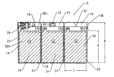
Referring to the drawings in general and to Figure 1
in particular, a battery 10 is depicted schematically in vertical
section. Battery 10 is housed within and includes a case 28
having a jar.or body portion 14 and a cover 16 fitting on the top
of jar 14. Cover 16 is preferably equipped with a lip fitting
over an upstanding exterior surface of jar 14 in the region of
jar-cover juncture. The lip is designated 38 in Figure 1.
The vertical extremity of jar 14 preferably fits within
a groove formed in a downwardly facing surface of cover 16. This
"tongue in groove" construction is visible adjacent to lip 38 in
Figure 1, but the construction has not been numbered, to aid
drawing clarity. The flat, horizontal bottom portion of jar 14
is designated 18; vertically upstanding sides of jar 14 are
designated 20. Jar 14 preferably has a plurality of internal
vertically upstanding partitions 22 defining, together with jar
sides 20 and jar bottom 18, cell compartments 12 within which
recombinant lead-acid electrical cells, shown schematically and
designated generally 34, reside. Juncture of jar 14 and cover
CA 02335135 2000-12-14
WO 99/66582 PCT/US99/13578
16 in the battery interior has been depicted by a line 38J; jar-
cover juncture line 38J has not been illustrated in the central
one of cell compartments 12 in Figure 1 to enhance drawing
clarity and visualization of the head space.
Each cell compartment 12 preferably housings a single
electro-chemical cell where the cell preferably includes a
plurality of positive lead metal plates, a plurality of negative
lead metal plates and, preferably, absorbent glass mat separator
material between the positive and negative plates. The absorbent
glass mat separator material absorbs sulfuric acid electrolyte
solution thereby maintaining electrolyte in contact with the
surfaces of the preferably alternating, interleaved positive and
negative lead metal plates. The plates are preferably connected
in parallel to provide a single lead-acid cell having a nominal
voltage of 2.26 volts.
The lead metal plates are depicted schematically in
Figure 1 and designated generally 500; the absorbent glass mat
separator material is not depicted in Figure 1.
Cells in respective compartments 12 are preferably
connected in series one with another thereby to provide a desired
output of 6 or 12 volts from battery 10. In the configuration
illustrated schematically in Figure 1, with three cells connected
together in series, the battery would have a nominal output
voltage slightly above 6 volts. Different numbers and
combinations of cells and cell connections can be used to
effectuate desired battery voltage and current output levels.
Referring to Figure 2, jar internal partitions 22
preferably include notch portions at their upper extremities,
resulting in partitions 22 having portions which are vertically
shortened, stopping short of jar cover 16. The un-notched upper
extremity portions of jar internal partitions 22 are designated
30 in Figure 2 and the upper extremities of the notched portions
of partitions 22 are designated 36 in Figure 2.
Spacing of upper extremities 36 of the notched portions
of jar internal partitions 22 away from a lower surface 32 of
cover 16, together with appropriate sizing and dimensioning of
the lead metal plates and separators fitting within cell
CA 02335135 2000-12-14
WO 99/66582 PCT/US99/13578
11
compartments 12, provides a head space 24 within jar 14 above
each of cells 34. Presence of head spaces 24, with apertures
such as notches 36 providing vapor transfer passageways between
and among individual cells, permits direct vapor mass transfer
and partial pressure equalization among two or more communicating
cells 34.
A catalyst unit, such as one of the combination vent
valve-catalyst carrier assemblies 100 illustrated in Figures A
through N, fits within catalyst unit receptacle 26 formed in
cover 16 and illustrated in Figure 1 and communicates with a head
space 24 via which two or more cells are in vapor communication.
As a result, hydrogen and oxygen, which evolve from the lead
metal plates as the electrochemical reaction proceeds, come into
vapor communication with one another and with catalyst material
within the catalyst unit and recombine into water or water vapor.
The catalyst unit residing in receptacle 26 has a catalyst
material, preferably palladium, therein and exposes the evolved
hydrogen and oxygen within battery 10 resulting from the
electrochemical reaction to the catalyst material within catalyst
unit 26. This enhances recombination of the hydrogen and oxygen
into water or water vapor within battery 10.
In the preferred practice of the invention
substantially no liquid phase water results from the
recombination of hydrogen and oxygen in the presence of the
catalyst. This is believed to be due to the high heat of
reaction of the recombination process in the presence of the
catalyst. The hydrogen and oxygen, when recombining, go directly
to vapor phase water, i.e. steam, with the reaction occurring at
a temperature in the neighborhood of 400 Fahrenheit.
Water vapor resulting from the recombination of the
hydrogen and oxygen initially creates a somewhat higher partial
pressure of water vapor in the vicinity of the catalyst unit
residing in receptacle 26 and communicating with head space 24.
Pressure always seeks to equalize itself within battery
10; as the partial pressure of water equalizes within a given
group of vapor-communicating cells 34 within battery 10, the
water vapor resulting from the recombination of hydrogen and
CA 02335135 2000-12-14
WO 99/66582 PCT/US99/13578
12
oxygen distributes itself evenly throughout a given multiplicity
of vapor-communicating cells 34 and vapor-communicating cell
compartments 12 within battery 10. Additionally contributing to
uniformity of conditions within battery 10, those of cells 34
needing water have relatively higher partial pressures of acid
and lower partial vapor pressures of water. These conditions
encourage water vapor to migrate to those of the vapor-
communicating cells which have the most acid and the least water
and therefore need water vapor the most.
Figures 3 and 4 depict in schematic form a catalyst
equipped vapor communicating multi-cell valve regulated lead-acid
battery manifesting aspects of the invention in which the lead-
metal plates and separators are positioned in horizontal planes.
In Figure 3 the battery having its lead-metal plates in a
horizontal, sandwiched configuration is designated generally 10A
and includes a jar designated generally 14A and a cover
designated generally 16A. Positive and negative lead metal
plates are designated generally 300, 302 respectively and are
shown in schematic form in both Figure 3 and Figure 4. Absorbent
glass mat separator material positioned between positive plate
300 and negative plate 302 is designated generally 304 and has
been depicted between only some of positive and negative plates
300, 302 in Figures 3 and 4, to aid drawing clarity.
In the "pancake" style battery embodying the invention
as depicted in Figures 3 and 4, the case for the battery
consisting of jar 14A and cover 16A may have a plurality of cell
compartments, some of which has been designated generally 12A,
formed by vertical and horizontal partitions respectively
designated 306, 308 in Figures 3 and 4.
Two catalyst units are positioned in a vertical side
wall 312 of battery 10A. The catalyst units are preferably
combination vent valve-catalyst carrier assemblies 100 of one of
the types illustrated in Figures A through 10.
Horizontal partition 308 divides battery l0A into upper
and lower compartments. In the embodiment illustrated in Figures
3 and 4, there is no liquid or vapor communication between upper
and lower cell compartments since horizontal partition 308
CA 02335135 2000-12-14
WO 99/66582 PCT/US99/13578
13
completely separates the upper cell compartments from the lower
cell compartments by extending fully between all four vertical
side walls of the battery case. The battery case may be
fabricated with vertical side wall 312 as the cover and jar 14A
forming the remaining five sides of the rectangular solid
configuration of battery 10A.
As shown in Figure 4, vertical partitions 306 have
vertically extending edges 314 which are proximate to but spaced
from the inner surface of vertical side wall 312 to define
horizontally extending upper and lower head spaces designated
316U, 316L respectively. These head spaces extend the
longitudinal length of battery l0A where longitudinal is the
direction indicated by arrow L in Figure 3. By virtue of the
spacing of vertical edges 314 of vertical partition 306 from the
interior surface of vertical side wall 312, upper and lower head
spaces 316U, 316L respectively vapor communicate with all of the
upper and lower cells 12A of battery 10A.
For manufacturing convenience or to promote vapor
communication among the cells, vertical edge 314 of vertical
partition 306 may include a notch such as designated 318 in
Figure 4.
As depicted in Figures 3 and 4, it is not necessary for
a vent valve-catalyst carrier assembly 100 to be positioned
symmetrically or even at the centers of respective upper and
lower head spaces 316U, 316L. Despite the static, non-dynamic
nature of the environment in which batteries embodying the
invention are typically maintained and operate, with the absence
of significant changes in physical parameters of the environment
surrounding the battery over long periods of time, there is
nevertheless sufficient mass transfer vapor communication among
the vapor communicating cells within the battery that catalyst
material in a single vent valve-catalyst carrier assembly 100
effectively serves all of the cells which communicate via a
single common head space such as 316U or 316L.
A second pancake configuration battery embodying
aspects of the invention is depicted schematically in Figures 5,
6 and 7 where the battery is designated generally 10B and
CA 02335135 2000-12-14
WO 99/66582 PCT/US99/13578
14
includes a jar designated generally 148 and a cover designated
generally 168. In the embodiment illustrated in Figures 5, 6 and
7 battery 108 includes positive and negative lead metal plates
designated generally 300, 302 respectively and absorbent glass
mat separator material between the positive and negative plates
300, 302; the absorbent glass mat separator material has been
designated generally 304 and is shown between only some of the
lead metal plates to enhance drawing clarity.
Jar 148 illustrated in Figures 5, 6 and 7 includes a
pair of vertical partitions 3068 and a horizontal partition 3088
located at the approximate vertical midpoint of jar 148. As
illustrated in Figure 7, horizontal partition 3088 has an edge
318 which is displaced from the interior surface of vertical side
wall 3128, where vertical edge 318 has been depicted in dotted
lines to enhance drawing clarity. Displacement of vertical edge
318 of vertical partition 3068 from the interior surface of
vertical side wall 3128 creates a common head space 248 extending
the vertical height of battery lOB and the longitudinal length
of battery 108. A single vent valve-catalyst carrier assembly
100 is positioned for vapor communication with head space 248,
with vent valve-catalyst carrier assembly 100 being positioned
in cover 168 at the upper extremity of head space 248 as
illustrated in Figure 7.
As further illustrated in Figure 7, jar 148 may include
one or more horizontal partitions 3088 which desirably extend
laterally from side wall 312I towards vertical side wall 3128 but
stop short thereof, desirably by the same distance vertical edge
318 of vertical partition 3068 is separated from vertical side
wall 3128. The edge of horizontal partition 3088 which is spaced
away from vertical side wall 312B is denoted 320 and is best
illustrated in Figure 5. Horizontal partitions 3088 may be
provided to divide jar 148 into a desired number of cell
compartments and may further be provided to strengthen jar 148.
An upper one of horizontal partitions 3088 illustrated in Figure
7 may optionally be provided to effectuate pressure maintenance
on plates and separators of a cell and may be spaced from cover
168 in the manner illustrated in Figure 7. In battery lOB a
CA 02335135 2000-12-14
WO 99/66582 PCT/US99/13578
single vent valve-catalyst carrier assembly 100 serves all six
lead-acid cells of battery 10B.
Referring to Figures A through H, a vent valve-catalyst
carrier assembly suitable for installation in a multi-cell common
head space recombinant valve regulated lead-acid battery
practicing the invention is designated generally 100.
Vent valve-catalyst carrier assembly 100 carries a
catalyst material which enhances recombination of hydrogen and
oxygen gas produced during the electrolytic reaction within the
lead-acid battery. Vent valve-catalyst cover assembly 100 is
positioned to provide pressure relief from within battery 10 to
atmosphere upon pressure within battery 10 reaching a
predetermined level.
Vent valve-catalyst carrier assembly 100 preferably
extends into battery 10 via an apertured vent valve-catalyst
carrier assembly receptacle 26 formed in battery cover 16.
Receptacle 26 preferably includes an integrally molded
cylindrical collar 42. Vent valve-catalyst cover assembly 100,
when in place within receptacle 26, vents gas from inside battery
10 when pressure exceeds a predetermined level. A catalyst
carrying plug 32 is supported at the end of the vent valve-
catalyst carrier assembly 100 which is inside battery 10 and
promotes recombination of hydrogen and oxygen to minimize water
loss from battery 10.
Vent valve-catalyst carrier assembly 100 includes a
preferably injection molded body 102 having upper and lower
cylindrical portions with the upper portion denoted 104 and being
of larger diameter and the lower portion denoted 106 and being
of smaller diameter. Upper and lower cylindrical body portions
are connected by an annular web 108. Extending across the open
interior at the upper end of lower cylindrical body portion 106
is a valve seating web designated generally 110 in which a valve
stem member 112 is retained.
Extending downwardly from the cylindrical interior of
lower cylindrical body portion 106 is a cage designated generally
114.
Slidably retained within cage 114 is a catalyst
CA 02335135 2000-12-14
WO 99/66582 PCT/US99/13578
16
carrying plug 32 within which are particles or granules of
catalyst material designated C in Figure E.
Cage 114 includes axially elongated rail members 116
and an annular outer ring portion 118 in which are formed
apertures 120, best seen in Figures F and H, which receive
downwardly extending nibs 122 which are integral with and formed
as a part of lower cylindrical body portion 106.
Extremities of rail members 116 at the lower end of
cage 114 curve radially inwardly to join one another and form a
cross configuration at the bottom of cage 114. These lower
extremities of rail members 116 are designated generally 124 in
Figure D and form the cross illustrated in Figure D.
An annular interior shoulder 132 formed in the inner
surface of upper cylindrical body portion 104 proximate the top
end thereof is shown in Figure C and provides a shoulder for
support of a porous disk 128 which is preferably formed of porous
polyethylene and serves to block flames or sparks from passing
through the vent valve portion of the vent valve-catalyst carrier
assembly 100. A vent valve-catalyst carrier assembly cover 126
covers the axially facing exterior of upper cylindrical body
portion 104 and preferably fractionally couples to upper
cylindrical body portion 104 via vent valve cover tabs 130 which
are positioned to fit snugly within the cylindrical open interior
of upper cylindrical body portion 104 proximate the upper
extremity thereof. Vent valve-catalyst carrier assembly cover
126 includes apertures 134 through which gas may pass.
Preferably the unitary piece which includes upper cylindrical
body portion 104, lower cylindrical body portion 106 and annular
web 108 is molded polypropylene.
In Figure C an 0-ring 136 is depicted around the
cylindrical exterior of lower cylindrical body portion 106
proximate to juncture of lower cylindrical body portion 106 and
annular web 108. 0-ring 136 provides a gas-tight seal between
vent valve-catalyst cover assembly 100 and body cover 16 when
vent valve-catalyst cover assembly 100 is in place.
Formed about the lower annular exterior of lower
cylindrical body portion 106 are at least a pair of angularly
CA 02335135 2000-12-14
WO 99/66582 PCT/US99/13578
17
tapered ramming shoulders 13 8 . These ramming shoulders 13 8 taper
in an angular direction as illustrated in Figure D, growing in
size in the radial direction with angular travel about the
circular outer periphery of lower cylindrical body portion 106.
The portions of angularly tapered ramming shoulders 138
illustrated in Figure C are the shoulder portions of maximum
radial thickness. As illustrated in Figure D, these portions
taper down with angular position in a counter-clockwise direction
in Figure D, to a position of tangency with the cylindrical outer
surface of lower cylindrical body portion 106.
At the position of maximum radial thickness, angularly
tapering ramming shoulders 138 include radially extending
(upwardly in Figure C, but downwardly in Figure D) ramming blocks
140. Radially extending ramming blocks 140 are adapted for
ramming contact with corresponding opposed ramming blocks 142
which are preferably molded in place within a cylindrical
passageway formed in battery cover 16 which receives vent valve-
catalyst carrier assembly 100. The radially facing (upper in
Figure C, lower in Figure D) surfaces of radially extending
ramming blocks 140 are movable ramming surfaces 144 cooperating
with complementally shaped downwardly facing ramming surfaces 146
formed on ramming blocks 148 which are preferably molded in place
within the cylindrical interior of receptacle 26 in cover 16
within which vent valve-catalyst carrier assembly 100 fits.
As seen in Figure C, catalyst carrying plug 32 is
preferably sealed at one end by epoxy 92. Catalyst carrying plug
32 is gas permeable for the catalyst to aid in recombination of
hydrogen and oxygen within battery 10 to ensure battery 10 does
not prematurely fail due to water loss.
Cage 114 and catalyst carrying plug 32 are preferably
located along a gas flow path within battery 10. Catalyst
carrying plug 32 preferably has an axial dimension less than
length of cage 114 such that catalyst carrying plug 32 can move
axially for free gas flow about catalyst carrying plug 32. The
radial dimension of catalyst carrying plug 32 is selected so that
plug 32 may slidably contact the rail members of cylindrical cage
114.
CA 02335135 2000-12-14
WO 99/66582 PCT/US99113578
18
Valve openings 200 shown in Figure E permit gas flow
through vent valve-catalyst cover assembly 100.
Valve member 56 illustrated Figure C is preferably a
flexible inverted mushroom-shaped member 56, preferably made of
rubber, having a cap 202 and a valve stem 112 extending through
valve aperture 86. When valve stem 112 is snugly received in
valve aperture 86 in web 110, peripheral edge 202a of valve
member 56 covering valve openings 200 rests on valve seating web
110, in sealing contact with web 110 in the valve closed position
illustrated in Figure C. In this position, valve member 56 seals
valve openings 200 closed. Valve member 56 is secured in
position by engagement of a narrow waist portion 204a beneath
aperture 86 in valve seating web 110 as shown in Figure E which
resists upward motion of valve member 56. Downward movement of
valve member 56 is precluded by cap 202 which has a radial
dimension much greater than valve aperture 86.
If pressure builds within the battery case, gas may
pass between rail members 116 and into the open interior 208 of
lower generally cylindrical portion 106, to exert force on the
underside of mushroom-shaped cap 202 to unseat mushroom-shaped
cap 202 from valve seating web 110.
Open interior 208 of lower cylindrical body portion 106
for gas flow therein is shown in Figure D. The specific
actuation properties of the valve to facilitate pressure relief
are determined by choice of the rubber utilized to manufacture
mushroom-shaped cap 202. For example, a rubber durometer value
of 50 yields a differential pop-off pressure of 0.5 to 5.0 psi.
As pressure rises above the selected threshold, mushroom-shaped
cap 202 unseats, permitting gas flow upwardly through valve
openings 200.
Figures I and J show a vent valve-catalyst carrier
combination 100' employing a different valve construction but
embodying broad structural features of the vent valve-catalyst
cover assembly 100 shown in Figures A through E. Since the
structures are similar in many ways, corresponding parts have
been given similar number designations with the addition of
primes thereto.
CA 02335135 2000-12-14
WO 99/66582 PCT/US99/13578
19
In vent valve-catalyst cover assembly 100' illustrated
in Figures I and J, lower cylindrical body portion 106', which
fits into receptacle 26 in cover 16 similarly to body portion 106
shown in Figure C, has angularly tapered caroming shoulders 138'.
The upper surfaces of those shoulders provide movable caroming
surfaces 144' which cooperate with cam surfaces similar to those
of angularly tapered caroming shoulders 138 in Figure C on lower
cylindrical body portion 106. Upper cylindrical body portion
104' does not serve as part of the vent body. Instead, upper
cylindrical body portion sidewall 52' is connected to lower
cylindrical body portion 106' by upper cylindrical body portion
bottom 58' through which lower cylindrical body portion 106'
extends, almost to the top of the upper cylindrical body portion
sidewall 52'. Thus an annular groove is formed to receive vent
valve cover tabs 130' which are near the edge of vent valve-
catalyst carrier assembly cover 126'.
Vent valve-catalyst carrier assembly cover 126' is
flush with the top edge of the upper cylindrical body portion
sidewall 52' so that not only is gas flow confined within lower
cylindrical body portion 106', but a different appearance
results. The valve is wholly within the lower cylindrical body
portion 106' so that the vent channel is through an integrally
molded barrier across the bottom of the lower cylindrical body
portion 106'. Again, a porous fire wall is provided by porous
disk 128' which rests on annular interior shoulder 132' at the
top of lower cylindrical body portion 106'.
The outside profile seen in Figure I is essentially the
same as that of the structure of Figures A through E and the
insertion into receptacle 26 of battery cover 16 and coupling to
the collar (42) is the same as described in connection with
Figures A through H. Furthermore, the catalyst container may be
the same with the same catalyst material sealed therein with
epoxy in the same way and supported in the same structure, all
as shown in Figures F through H.
In Figures I and J the valve structure includes an
axially oriented cylindrical tubular member 210 preferably molded
of the same resinous material as the rest of the valve body to
CA 02335135 2000-12-14
WO 99/66582 PCTIUS99/13578
which it is connected by a barrier annular web 212 which extends
inward from and lies flush with the bottom of lower cylindrical
body portion 106'. At the top of cylindrical tubular member 210
is an integral ring 214 having radial slots 214a therethrough the
ring. Covering the cylinder and integral ring 214 is an inverted
cup 216 preferably made of rubber, a rubber-like material or some
other material having similar elastic resilient properties and
good frictional adherence to cylindrical tubular member 210 and
integral ring 214 which it surrounds.
Increase of differential pressure inside the battery
to a predetermined amount above atmospheric moves the flexible,
stretchable sidewalls of inverted cup 216 away from the outside
of the cylindrical tubular member 210 and integral ring 214 so
that gas may pass through slots 214a, down past the sidewalls of
inverted cup 216, up through porous disk 128', and out through
apertures 134' of the vent valve-catalyst carrier assembly cover
126'. The durometer range for inverted cup 216 is essentially
the same as for valve member 56.
Referring to Figures K through N, another embodiment
of a vent valve-catalyst carrier assembly suitable for
installation in a multi-cell common head space recombinant valve-
regulated lead-acid battery practicing the invention is
designated generally 100". Vent valve-catalyst carrier assembly
100" includes a preferably injection molded body 102" having
upper and lower cylindrical portions, with the upper portion
denoted 104" and being of larger diameter and the lower portion
denoted 106" and being of smaller diameter. Upper and lower
cylindrical body portions are connected by an annular shoulder
108" . Extending across the open interior at the upper end of
lower cylindrical body portion 106" as an extension of shoulder
108" is a valve seating web designated generally 110".
Extending downwardly from the cylindrical interior of
lower cylindrical body portion 106" is a cage designated
generally 114".
Slidably retained within cage 114" is a catalyst
carrying plug 32 within which is the catalyst material.
CA 02335135 2000-12-14
WO 99166582 PCT/US99/13578
21
Cage 114" includes axially elongated rail members 116"
and an annular outer ring portion 118" in which are formed
apertures 120", similar to those illustrated in Figures F and H,
receiving downwardly extending nibs 122 " which are integral with
and formed as a part of lower cylindrical body portion 106".
Extremities of rail members 116" at the lower end of
cage 114" turn radially inwardly to join one another and form a
cross configuration at the bottom of cage 114". These lower
extremities of rail members 116" are designated generally 124"
in Figure L and form a cross as illustrated in Figure L.
An annular interior shoulder 132" formed in the inner
surface of upper cylindrical body portion 104" proximate the top
end thereof is shown in Figure N and provides a shoulder for
support of a porous disk 128" which is preferably formed of
porous polyethylene and serves to block flames or sparks from
passing through the vent valve portion of the vent valve-catalyst
carrier assembly 100". A vent valve-catalyst carrier assembly
cover 126" covers the axially facing exterior of upper
cylindrical body portion 104" and preferably fractionally couples
to upper cylindrical body portion 104" via vent valve cover tabs
130" which fit snugly within cylindrical interior of upper
cylindrical body portion 104" proximate the upper extremity
thereof. Vent valve-catalyst carrier assembly cover 126"
includes apertures 134" through which gas may pass. Preferably
the unitary piece which includes upper cylindrical body portion
104", lower cylindrical body portion 106" and annular shoulder
108" is molded polypropylene.
In Figure N an 0-ring 136" is depicted around the
cylindrical exterior of lower cylindrical body portion 106"
proximate to juncture of lower cylindrical body portion 106" and
annular shoulder 108". 0-ring 136" provides a gas-tight seal
between vent valve-catalyst cover assembly 100" and battery cover
16 when vent valve-catalyst cover assembly 100" is in place.
Formed about the lower annular exterior of lower
cylindrical body portion 106" are at least a pair of angularly
tapered camming shoulders. These caroming shoulders taper in an
angular direction growing in size in the radial direction with
CA 02335135 2000-12-14
WO 99/66582 PCT/US99/13578
22
angular travel about the circular outer periphery of lower
cylindrical body portion 106". These shoulders taper with
angular position in a counter-clockwise direction to a position
of tangency with the cylindrical outer surface of lower
cylindrical body portion 106".
At the position of maximum radial thickness, angularly
tapering ramming shoulders include radially extending ramming
blocks 140" . Radially extending ramming blocks 140" are adapted
for ramming contact with corresponding opposed ramming blocks
which are preferably molded in place within the cylindrical
passageway of receptacle 26 formed in battery cover 16 which
receives vent valve-catalyst carrier assembly 100". The radially
facing surfaces of radially extending ramming blocks 140" are
movable ramming surfaces 144" which cooperate with complementally
shaped downwardly facing ramming surfaces formed on the ramming
blocks which are preferably molded in place within the
cylindrical passageway of receptacle 26 in cover 16, within which
vent valve-catalyst carrier assembly 100" fits, in the manner
described above with respect to ramming shoulder 138' and Figures
C and D.
As seen in Figure N, catalyst carrying plug 32 is
preferably sealed at one end by epoxy. Catalyst carrying plug
32 is gas permeable for the catalyst to aid in recombination of
hydrogen and oxygen within battery 10.
Cage 114" and catalyst carrying plug 32 are preferably
located along a gas flow path within battery 10. Catalyst
carrying plug 32 preferably has an axial dimension less than
length of cage 114" such that catalyst carrying plug 32 can move
axially and there is free gas flow about catalyst carrying plug
32. The radial dimension of catalyst carrying plug 32 is
selected so that plug 32 may slidably contact the rail numbers
of cylindrical cage 114".
Valve seating web 110" is molded integrally as an
extension of annular shoulder 108". Valve seating web 100"
includes at least one pressure relief aperture 316 and at least
one vacuum relief aperture 318. Surrounding aperture 316 is an
outwardly projecting cylindrical nozzle 360 integrally molded
CA 02335135 2000-12-14
WO 99/66582 PCT/US99/13578
23
with and supported on seating web 110". Nozzle 360 has lateral
vent slots 360a at its edge remote from shoulder 108".
Surrounding aperture 318 is an inwardly projecting
cylindrical nozzle 362 integrally molded with seating web 110".
Nozzle 362 has lateral vent slots 362a at its inner edge remote
from shoulder 108". Slots 360a and 362a give their respective
nozzles a castellated appearance. Alternatively, vent holes may
be provided through nozzles 360 and 362 near their ends remote
from shoulder 108".
Covering nozzle 360 is snugly fitting resilient cup
320, made of rubber or other elastic material, whose side walls
snugly engage those of nozzle 360. A cup 366 is similar to cup
320 and is similarly secured to nozzle 362 by fractionally
engaging overlying sidewalls.
Operation of nozzle-cup combinations 360, 320 and 362,
366 is dependent upon internal gas pressures which overcome the
resilient forces holding the cup sidewalls to the nozzle
sidewalls to permit gas to escape or enter at the lip of the cup
between the side walls of the cup and the nozzle walls. Upward
movement of cup 320, if it would occur at all, is limited to the
spacing between nozzle 360 and porous disk 128", which distance
is shorter than the length of the cup sidewalls. In addition to
functioning as a stop or limiting barrier, porous disk 128" also
acts as a fire barrier.
The elastic force of cup 320 on nozzle 360 tends to
hold cup 320 in place. As pressure builds within the battery
case, the gas exerts a force laterally upon cup 320 sidewalls
through vents 360a. After pressure exceeds a predetermined
threshold, cup 320 sidewalls unseat from nozzle 360 sidewalls
sufficiently to discharge gas from the battery case to atmosphere
external of the battery through cup walls 320 up through porous
disk 128" and vents 134" in cover 126". Cup 320 is retained in
position by sidewall contact friction with the nozzle. Should
cup 320 unseat, however, porous disk 128" acting as limiting
means will prevent sufficient movement to bring the end of cup
320 sidewalls above vents 360a.
CA 02335135 2000-12-14
WO 99/66582 PCT/US99/13578
24
Porous disk 128" is supported on shoulder 132" molded
into sidewall of upper cylindrical body portion 104" and held in
place by vent valve cover tabs 130" fictionally engaged on the
inner wall of upper cylindrical body portion 104".
Operation of cup 366 relative to nozzle 362 is
essentially the same but reversed in direction since it is a
partial vacuum inside the battery case which causes the action.
The higher atmospheric pressure which extends inside upper
cylindrical body portion 104" and moves the sidewalls of cup 366
away from nozzle 362. Higher pressure atmospheric air then flows
through the space created by deflection of the cup walls to
increase pressure within the battery. Should there be a tendency
for cup 366 to displace axially from nozzle 362, movement of cup
366 much less than required to move the lip of the cup as far as
the nozzle vents 362a will be prevented by porous wall 384.
Wall 384 is supported by an integral ring structure carried by
rails 116".
Actuation of either cup 320 or 366 to facilitate
pressure release is dictated by the properties of the rubber
utilized to manufacture the cup and the elastic release force
along the nozzle surface. For example, a rubber composition
having a durometer value of 50 yields a release pressure of 0.5
to 5.0 p.s.i. As pressure rises above the durometer-controlled
threshold, the cup sidewalls unseat, discharging gas between
those walls and the walls of its supporting nozzle.
Most desirably the catalyst material and catalyst unit
residing in receptacle 26 are maintained within head space 24.
As illustrated in Figure 1, the lead metal plates 500
of the battery have upstanding tabs for connection purposes,
which tabs have not been numbered. Plates of like polarity in
adjacent cells may be connected by lead metal straps, such as
indicated by 550 in Figure 1, where the lead metal straps may be
welded to the tabs of the plates in an advantageous manufacturing
procedure. A significant advantage of the invention is that with
common head space, which is identified as 24 in Figure 1, welding
of connection straps 550 to plates 500 of cells and other welding
connections which are desirably made in lead-acid batteries to
CA 02335135 2000-12-14
WO 99/66582 PCT/US99/13578
provide good electrical and structural connection, may be made
without risk to the usually plastic and therefore easily
thermally degraded case. With the common head space battery of
the invention, the vapor communication passageways between
communicating cells may be made sufficiently large so that
connecting straps 550 pass easily therebetween without being in
close proximity to plastic portions of the case, thereby reducing
the risk of damage to the case during welding operations.
It is within the scope of the invention to have the
connection straps 550 pass through internal partitions within the
battery case separating cells one from another or to pass above
those partitions or to be in contact with those partitions.
While the battery embodying the invention in schematic
forms in Figure 1 has been illustrated with a front terminal
access, the invention is not limited to front terminal access
batteries. The access terminals may be provided in any position.
The catalyst carrying plug may be a porous ceramic.
One suitable ceramic material for catalyst carrying plug 32 is
marketed by the General Electric Company under the trademark
Baton. Additional suitable materials are metal lattices and
other sufficiently porous materials which are inactive or inert
with respect to the catalyst and can survive the acidic vapor
environment within a lead-acid battery.
The invention embraces the combination of catalysts and
cells in any number, so long as the number of communicating cells
is greater than the number of communicating catalyst units, i.e.
so long as at least one catalyst unit serves more than one vapor-
communicating cell or cell compartment. Additionally, multiple
catalysts may be used, so long as the number of vapor-
communicating cells or cell compartments is greater than the
number of catalyst units serving that group of vapor-
communicating cells or cell compartments.
The invention further embraces the combination of
integral catalyst unit-vent valve combinations and cells in any
number where the number of communicating cells may be the same
as the number of catalyst unit-vent valve combinations. The
position of the catalyst in the common head space is not
CA 02335135 2000-12-14
WO 99/66582 PCT/US99/13578
26
critical.
EXAMPLE 1
One practice of the invention has involved two (2) 12
volt recombinant lead-acid batteries having six (6) cells each
with vertically oriented plates. The plates of these batteries
are approximately five inches (5") high, where height is
indicated by dimension A in Figure 1, and are approximately four
inches (4") wide, where plate width is indicated by dimension C
in Figure 1. The battery case is approximately six and one-half
inches (61/z") high in the inside, as indicated by dimension B in
Figure 1. These batteries have their six (6) cells aligned in
the longitudinal direction indicated by Arrow D in Figure 2, and
have vertical partitions separating the six (6) cells.
The six (6) cells are divided into two (2) groups, of
three (3) cells each, by a central internal vertically extending
partition. The two (2) groups of cells are physically and
chemically (but not electrically) isolated from one another;
there is no vapor or liquid communication between the two groups
of cells. However, there is vapor communication among the three
cells of a single group, as explained below.
Individual cells of each of two (2) groups of three (3)
adj oining cells share a common head space . The common head space
is created by the internal partitions within the battery jar,
separating the individual three (3) cells of a group from one
another, being notched at the upper extremities of the
partitions, in the manner indicated generally in Figure 2. The
notches are of a size convenient for fabrication purposes and are
on the order of about one inch ( 1 " ) in width and one-quarter inch
(1/4" ) to one half inch (1/z" ) in depth.
There is no aperture or cut-out in the center partition
separating the first group of three (3) cells from the second
group of three (3) cells. As a result these 12 volt batteries
embodying the invention have two (2) head spaces, with each one
of the three (3) cells in a respective group of cells sharing one
of the two head spaces in common with the remaining two (2) cells
of the group.
CA 02335135 2000-12-14
WO 99/66582 PCT/US99/13578
27
In this practice of the invention one (1) catalyst unit
is provided for each of the two ( 2 ) groups of three ( 3 ) cells .
Each catalyst unit is mounted on the battery cover immediately
above one of the notched partitions separating individual ones
of the three (3) cells from the remaining two (2) cells of a
group. The catalyst units are displaced transversely from the
position of the notch in the partition above which the catalyst
unit is mounted. In this practice of the invention the catalyst
units do not include vent valves in combination therewith.
These two (2) catalyst-equipped vapor-communicating
six-cell recombinant lead-acid 12 volt batteries embodying the
invention have been tested and found to compare very favorably
with commercially available 12 volt batteries sold under the
designation LS12-25 by C & D Technologies, Inc. Commercially
available C & D Technologies LS12-25 batteries are rated as being
capable of supplying a constant current of 4.8 amps over a five
(5) hour period without cell voltage falling below 1.75 volts.
Formation of water, through recombination of hydrogen
and oxygen, is desirable to maintain desired conditions within
the battery.
A test determined gassing characteristics of these two
batteries embodying the invention vis-a-vis the LS12-25 batteries
which are commercially available from C & D Technologies, Inc.
Gassing is a measure of hydrogen and oxygen gas which escapes
from the battery and hence is not available to form water in a
recombination reaction within the battery. Oxygen adversely
reacts with the negative grid and limits battery discharge
capacity. Hence, gassing is undesirable in a battery.
In testing, the catalyst-equipped vapor-communicating
multi-cell lead-acid recombinant 12 volt batteries embodying the
invention and the commercially available C & D Technologies LS12-
25 batteries used for comparison purposes were initially
maintained at a voltage of 2.26 volts per cell by application of
a small current, of sufficient magnitude to overcome the tendency
of the cells to self-discharge. This is commonly referred to as
maintaining the batteries "on float". Vdhile "on float", the
batteries were tested for gassing at the 2.26 volts/cell float
CA 02335135 2000-12-14
WO 99/66582 PCT/US99/13578
28
voltage.
The batteries were then measured to determine how they
performed with respect to the rated five (5) hour current
discharge capacity of the LS12-25 batteries, from a starting
voltage of 2.26 volts per cell. These measurements were
performed by drawing a constant current from each battery until
the battery voltage fell to 1.75 volts.
After discharge, each of the batteries was recharged
to a voltage of 2.26 volts per cell and then further charged to
a voltage of 2.35 volts per cell. Each battery was then measured
for gassing at the 2.35 volts per cell level. After being
measured for gassing, each of the batteries was further charged
to 2.45 volts per cell and again measured for gassing.
Table I presents the test results. The gassing data
are presented in cubic centimeters of measured gas per hour for
each battery.
Ta le I
Invention 12 Volt eatteriea Cononercially Available I2 Volt
rt~i2-25 Hatterias
~I ~a ~l ~z
2.26 v--gassing 0.04 0 0.85 0.32
2.35 v--gassing 0 0 9.1 11.4
2.45 v--gassing 0 0 47.1 54.6
$ 5 hr. cap. >117.6$ 109$ 110.3$ 115.6$
to 1.75 v
Surprisingly, one catalyst-equipped vapor-communicating
mufti-cell recombinant 12 volt lead-acid battery embodying the
invention evolved only four one-hundredths (0.04) of a cubic
centimeter of measurable gas per hour while being floated at 2.26
volts per cell. The same battery evolved no measurable gas at
2.35 volts per cell nor at 2.45 volts per cell, as illustrated
in Table I, even though there was only a single catalyst unit for
each group of three cells. Even though two cells (of each group
of three) had to depend on mass transfer among the cells via the
common head space for vapor communication with the catalyst,
gassing of the battery as a whole was negligible and not even
measurable (if there was any gassing at all) at the two higher
cell voltages.
CA 02335135 2000-12-14
WO 99/66582 PCT/US99/13578
29
Also surprisingly, as evident from Table I, a second
catalyst-equipped vapor-communicating multi-cell 12 volt lead-
acid recombinant battery embodying the invention did not evolve
any measurable amount of gas while being floated at 2.26 volts
per cell, nor while maintained at 2.35 volts per cell and 2.45
volts per cell, even though there was only a single catalyst unit
for each group of three cells . Even though two cells of each
group of three had to depend on mass transfer among the cells via
the common head space for vapor communication with the catalyst,
gassing of the battery was not measurable.
As further evident from Table I, both of these
catalyst-equipped vapor-communicating multi-cell 12 volt lead-
acid batteries embodying the invention exceeded the rated five
(5) hour discharge capacity of the comparable commercially
available C & D Technologies LS12-25 batteries.
Other than presence of the catalyst units and provision
of common head spaces for each group of three (3) cells, the
catalyst-equipped vapor-communicating multi-cell 12 volt lead-
acid recombinant batteries embodying the invention, for which the
test data is set forth in Table I, were identical to commercially
available C & D Technologies LS12-25 lead-acid batteries.
As apparent from Table I, the commercially available
C & D Technologies LS12-25 lead-acid batteries evidenced much
greater gassing than the catalyst-equipped vapor-communicating
multi-cell 12 volt lead-acid recombinant batteries embodying the
invention. Specifically, the lowest rate of gassing by one of
the LS12-25 batteries was eight (8) times that of the only
measurable gassing of one of the catalyst-equipped vapor-
communicating mufti-cell 12 volt lead-acid recombinant batteries
embodying the invention.
EXAMPLE 2
Another practice of the invention has involved two 12
volt recombinant lead-acid batteries having six (6) cells each.
The plates of these batteries are approximately seven inches ( 7 " )
high, where height is indicated by dimension A in Figure 1, and
are approximately five inches (5") wide, where plate width is
CA 02335135 2000-12-14
WO 99/66582 PCT/US99/13578
indicated by dimension C in Figure 1. The battery case is
approximately eight inches (8") high in the inside, as indicated
by dimension B in Figure 1. These batteries have their six (6)
cells oriented in two (2) groups of three (3) cells each, where
the two groups of cells are adjacent one to another, and the
three cells of each group are aligned in the longitudinal
direction indicated by Arrow D in Figure 2. Vertical partitions
separate the six (6) cells. There is vapor communication among
cells of a single group, as explained below.
The six (6) cells are divided into two (2) groups of
three (3) cells each by a central internal vertically extending
partition. The two (2) groups of cells are physically and
chemically (but not electrically) isolated from one another;
there is no vapor or liquid communication between the two groups
of cells . There is vapor communication among the three ( 3 ) cells
of a single group.
Individual cells of each of two (2) groups of three (3)
longitudinally adjoining cells share a common head space. The
two common head spaces are created by the transverse vertically
extending partitions within the battery jar, separating the
individual three ( 3 ) longitudinally aligned cells of a group from
one another, being notched at the upper extremities of the
partitions in the manner indicated generally in Figure 2. The
notches are of a size convenient for fabrication purposes and are
on the order of about one inch (1") in width and one-quarter inch
(1/4" ) to one half inch (1/z" ) in depth.
There is no notch, aperture or cut-out in the center
partition separating the first group of three (3) cells from the
second group of three (3) cells. As a result these 12 volt
batteries embodying the invention have two (2) head spaces, with
each one of the three (3) cells in a respective group of cells
sharing one of the two head spaces in common with the remaining
two (2) cells of the group, with both of the head spaces being
parallel with one another and extending the longitudinal length
of the battery case.
One (1) catalyst unit is provided for each of the two
(2) groups of three (3) cells. Each catalyst unit is mounted on
CA 02335135 2000-12-14
WO 99/66582 PCT/US99/I3578
31
the battery cover above the central cell of a group, at
approximately the longitudinal and transverse midpoint of the
cell. In this practice of the invention the catalyst units did
not include vent valves in combination therewith.
These two (2) catalyst-equipped vapor-communicating
six-cell recombinant lead-acid 12 volt batteries embodying the
invention have been found by testing to compare very favorably
with commercially available 12 volt batteries sold under the
designation FA12-125 by C & D Technologies, Inc. Commercially
available C & D Technologies FA12-125 batteries are rated as
being capable of supplying a specified constant current of 24.0
amps over a five (5) hour period without cell voltage falling
below 1.75 volts.
In testing, the catalyst-equipped vapor-communicating
multi-cell lead-acid recombinant 12 volt batteries embodying the
invention and the commercially available C & D Technologies FA12-
125 batteries used for comparison purposes were initially
maintained at a voltage of 2.26 volts per cell by application of
a small current to maintain the batteries "on float", as
explained above. While "on float", each of the batteries was
measured for gassing at the 2.26 volts/cell float voltage.
The batteries were then further charged to a voltage
of 2.35 volts per cell. Each battery was then measured for
gassing at the 2.35 volts per cell level. The batteries were
then further charged to 2.45 volts per cell and again measured
for gassing.
Table II presents the test results. The gassing data
are presented in cubic centimeters of measured evolved gas per
hour for each battery.
Table II
Data Presented as aassinp Rata in CC/ICt/CELL
~f a c .bn Z _ a 5 tlpc
sattW 1 ~. 1 a 1 Z
7r k
Invention0 0 0.62 0 1.2 0
Battery
Commercial0.93 1.4 16.8 ~.8 ----- -----
Available
FA12-125
Battery
CA 02335135 2000-12-14
WO 99/66582 PCT/US99/13578
32
Surprisingly, neither of the catalyst-equipped vapor-
communicating multi-cell recombinant 12 volt lead-acid batteries
embodying the invention produced any measurable gas while being
floated at 2.26 volts per cell. One of these batteries embodying
the invention similarly produced no measurable hydrogen gas at
2.35 and at 2.45 volts per cell, as set forth in Table II, even
though there was only a single catalyst unit for each group of
three cells. Even though in these batteries embodying the
invention two cells of each group of three had to depend on mass
transfer among the cells via the common head space for vapor
communication with the catalyst, gassing for one of these
batteries embodying the invention was negligible and indeed not
even measurable (if there was any gassing at all) across the
entire range of cell voltages.
Also surprisingly, as evident from Table II, a second
one of the catalyst-equipped vapor-communicating mufti-cell 12
volt lead-acid recombinant batteries embodying the invention did
not evolve any measurable amount of hydrogen gas while floated
at 2.26 volts per cell. That battery lost just 0.62 cubic
centimeters of gas per hour while at 2.35 volts per cell and only
1.22 cubic centimeters of gas per hour at 2.45 volts per cell,
even though there was only a single catalyst unit for each group
of three cells. Even though two cells of each group of three had
to depend on mass transfer among the cells via the common head
space for vapor communication with the catalyst, gassing of the
battery as a whole was so low as to be insignificant.
Other than presence of the catalyst units and provision
of common head spaces for each group of three (3) cells, the
catalyst-equipped vapor-communicating mufti-cell 12 volt lead-
acid recombinant batteries embodying the invention, for which the
test data is set forth in Table II, were identical to
commercially available C & D Technologies FA12-125 lead-acid
batteries.
As apparent from Table II, the commercially available
C & D Technologies FA12-125 lead-acid batteries evidenced much
greater gassing than the catalyst-equipped vapor-communicating
mufti-cell 12 volt lead-acid recombinant batteries embodying the
CA 02335135 2000-12-14
WO 99/66582 PCT/US99/13578
33
invention. Specifically, in three of the four conditions under
which gassing could be measured and compared, while there was no
measurable gassing of the catalyst-equipped vapor-communicating
multi-cell 12 volt lead-acid recombinant battery embodying the
invention, there was significant gassing in the commercially
available FA12-125 batteries. In the single instance where both
a battery embodying the invention and a commercially available
FA12-125 battery produced measurable gassing, the commercially
available FA12-125 batteries gassed at a rate at least an order
of magnitude greater than the battery embodying the invention.
The lowest rate of gassing by one of the FA12-125 lead-acid
batteries was an order of magnitude greater than that of the only
measurable gassing of one of these two catalyst-equipped vapor-
communicating multi-cell 12 volt lead-acid recombinant batteries
embodying the invention.
EXAMPLE 3
Yet another practice has involved two (2) 6 volt
recombinant lead-acid batteries having three (3) cells each. The
plates of these batteries are approximately seven inches (7")
high, where height is indicated by dimension A in Figure 1, and
are approximately six inches (6") wide, where plate width is
indicated by dimension C in Figure 1. The battery case is
approximately eight (8") high in the inside, as indicated by
dimension B in Figure 1. These batteries have their three (3)
cells aligned in the longitudinal direction. Comparable
commercially available C & D Technologies LS6-200 batteries are
rated as being capable of supplying a specified constant current
of 38.4 amps over a five (5) hour period without cell voltage
falling below 1.75 volts.
The three (3) cells are physically and chemically (but
not electrically) isolated from one another; there is no liquid
communication between the three groups of cells, but there is
vapor communication among the three (3) cells.
The three (3) groups of two adjacent cells all share
a common head space. The common head space is created by the
upper extremities of the internal partitions within the battery
CA 02335135 2000-12-14
WO 99/66582 PCT/US99/13578
34
jar, which separate the adjacent cells from each other, stopping
short of the battery cover. In these batteries embodying the
invention there are no notches, such as those illustrated
generally in Figure 2 in the vertically extending partitions.
Three (3) catalyst units are provided for each of the
batteries, located in the common head space shared by the three
(3) cells. The catalyst units are mounted on the battery cover
immediately above the internal partitions which divide the
battery interior into compartments. The catalyst units are
displaced transversely from the walls of the battery case.
These two (2) catalyst-equipped vapor-communicating
three-cell recombinant lead-acid 6 volt batteries have been
tested for weight loss, which occurs as a result of gassing, with
very favorable results.
In testing, these two catalyst-equipped vapor-
communicating multi-cell lead-acid recombinant 6 volt batteries
were maintained at a voltage of 2.26 volts per cell by
application of a small current, of sufficient magnitude to
overcome the tendency of the cells to self-discharge, referred
to as maintaining the batteries "on float". Wnile "on float",
each of the batteries was measured for weight loss.
V~hile "on float" the batteries were also periodically
tested to determine how they performed with respect to the rated
five (5) hour current discharge capacity of comparable C & D
Technologies LS6-200 batteries, from a starting voltage of 2.26
volts per cell. These measurements were performed by withdrawing
a constant current from each battery until the cell voltage in
the battery fell to 1.75 volts.
After each such discharge measurement, each of the
batteries was recharged to a level of 2.26 volts per cell and
returned to the float condition. During the entire test time,
both batteries were maintained in an environment at a 120~F
temperature, for 131 days. This is believed to be equivalent to
about 800 days of service at 77oF.
Other than presence of the catalyst units, the
catalyst-equipped vapor-communicating multi-cell 6 volt lead-acid
recombinant batteries embodying the invention, for which the test
CA 02335135 2000-12-14
WO 99/66582 PCT/US99/13578
data is set forth in Table III, were identical to commercially
available C & D Technologies LS6-200 lead-acid batteries.
Table III presents the test results.
Table III
rya a T~.. . Battai7l 71 Sattary H
;
0 111.9% 115.0%
50--Percent Rated Capacity 118.1% 117.3%
50 Weight Loss, grams 0 grams 6 grams
100--Percent Rated Capacity 117.1 115.2
100 Weight Loss, grams 60 52 (Total of 58?
131--Percent Rated Capacity 114.7 117.5
Remarkably, after fifty days in the 120~F temperature
environment, one of these batteries had not lost any weight
(indicating there was no gassing), whereas the second of these
batteries had lost only six grams of weight . Further remarkably,
after fifty days in the 120~F environment, both batteries
actually exhibited increases in discharge current capacity. One
of the batteries exhibited discharge current capacity 111.9 that
of the rated discharge current capacity of a comparable LS6-200
battery when the test began, while the second battery exhibited
discharge current capacity 115 that of the rated discharge
current capacity for a comparable C & D Technologies LS6-200
battery when the test began.
Even more remarkably, after 100 days in the 120oF test
environment, both of the batteries still exhibited increases in
discharge current capacity over and above those exhibited when
the test began. The discharge current capacity of battery A
dropped only by one percentage point (1~) between day 50 and day
100 and still remained over seventeen percentage points (17~) in
excess of the rated discharge current capacity of a comparable
commercially available LS6-200 battery when the test began.
After 100 days battery B experienced a drop in
discharge current capacity back nearly to the level of discharge
current capacity it had exhibited when the test began; both
batteries remained well above the rated discharge current
capacity for the comparable commercially available battery.
CA 02335135 2000-12-14
WO 99/66582 PCT/US99/13578
36
Further remarkably, after 100 days in the 120~F
environment, battery A had lost only sixty grams of weight; all
sixty grams were lost between the 50th and 100th day in the 120~F
environment. Battery B lost fifty-two grams of weight between
day 50 and day 100 meaning that at day 100, battery B lost a
total of fifty-eight grams of weight relative to what battery
B had weighed at the beginning of the test.
Further remarkably, after 131 days in the 120~F test
environment, both battery A and battery B had discharge current
capacities above that exhibited at the beginning of the test and
well above the rated current discharge capacity for a comparable
commercially available battery. Indeed, in the case of battery
B, the discharge current capacity actually increased between day
100 and day 131 in the 120~F test environment.