Language selection

Search

Patent 2335150 Summary

Third-party information liability

Some of the information on this Web page has been provided by external sources. The Government of Canada is not responsible for the accuracy, reliability or currency of the information supplied by external sources. Users wishing to rely upon this information should consult directly with the source of the information. Content provided by external sources is not subject to official languages, privacy and accessibility requirements.

Claims and Abstract availability

Any discrepancies in the text and image of the Claims and Abstract are due to differing posting times. Text of the Claims and Abstract are posted:

  • At the time the application is open to public inspection;
  • At the time of issue of the patent (grant).
(12) Patent Application: (11) CA 2335150
(54) English Title: CHAIR MECHANISM
(54) French Title: MECANISME DE CHAISE
Status: Dead
Bibliographic Data
(51) International Patent Classification (IPC):
  • A47C 1/032 (2006.01)
  • A47C 3/026 (2006.01)
(72) Inventors :
  • LIE, TORE (Norway)
(73) Owners :
  • RING MEKANIKK A.S. (Norway)
(71) Applicants :
  • RING MEKANIKK A.S. (Norway)
(74) Agent: AVENTUM IP LAW LLP
(74) Associate agent:
(45) Issued:
(86) PCT Filing Date: 1999-06-16
(87) Open to Public Inspection: 1999-12-23
Availability of licence: N/A
(25) Language of filing: English

Patent Cooperation Treaty (PCT): Yes
(86) PCT Filing Number: PCT/NO1999/000196
(87) International Publication Number: WO1999/065365
(85) National Entry: 2000-12-14

(30) Application Priority Data:
Application No. Country/Territory Date
19982788 Norway 1998-06-17

Abstracts

English Abstract


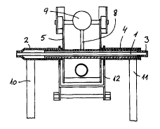
Chair mechanism especially for office chairs and larger arm chairs,
characterized in one end of a torsion spring (1) being fixedly connected with
one end of an inner pipe (3) being turnably supported in a pipe (4), the other
end being supported turnably in an outer pipe (2) which again is secured to
the other end of the spring (1), the outer pipe (2) and the pipe (4) being
fixedly connected with each other through an angle profile (12) securing a
fixed connection between the outer pipe (2), the pipe (4), the angle profile
(12), the seat (13) of the chair and the two back supports (10, 11) of the
chair which are secured at a distance from each other to respectively the
outer pipe (2) or the pipe (4), a pressure arm (8) being connected with a
centre portion of the inner pipe (3) between the pipe (4) and the outer pipe
(2) and the pressure arm (8) abutting with a prestress against a bow mechanism
(5) connected to the fundament of the chair and adjustable by means of a screw
(9).


French Abstract

Mécanisme de chaise conçu spécialement pour des chaises de bureau et des fauteuils plus grands et comportant à une extrémité un ressort de torsion (1) accouplé fixe à une extrémité d'un tube intérieur (3) supporté rotatif dans un tube (4), l'autre extrémité étant supportée rotative dans un tube extérieur (2) fixé à son tour à l'autre extrémité du ressort (1). Ce tube extérieur (2) et le tube (4) sont accouplés fixes l'un à l'autre par l'intermédiaire d'un profilé d'angle (12) effectuant un accouplement fixe entre le tube extérieur (2), le tube (4), le profilé d'angle (12), le siège (13) de la chaise et ses deux dossiers (10, 11) qui sont fixés à distance l'un de l'autre respectivement au tube extérieur (2) ou au tube (4). Un bras de pression (8) est accouplé à une partie centrale du tube intérieur (3) entre le tube (4) et le tube extérieur (2) et vient en butée avec une précontrainte contre un mécanisme d'inclinaison (5) accouplé à la base de la chaise et réglable au moyen d'une vis (9).

Claims

Note: Claims are shown in the official language in which they were submitted.

3

claim

Chair mechanism especially for office chairs and larger
arm chairs, CHARACTERIZED IN one end of a torsion spring (1)
being fixedly connected with one end of an inner pipe (3) being
turnably supported in a pipe (4), the other end being supported
turnably in an outer pipe (2) which again is secured to the other
end of the spring (1), the outer pipe (2) and the pipe (4) being
fixedly connected with each other through an angle profile (12)
securing a fixed connection between the outer pipe (2), the pipe
(4), the angle profile (12), the seat l13) of the chair and the
two back supports (10, 11) of the chair which are secured at a
distance from each other to respectively the outer pipe (2) or
the pipe (4), a pressure arm (8) being connected with a centre
portion of the inner pipe (3) between the pipe (4) and the outer
pipe (2) and the pressure arm (8) abutting with a prestress
against a bow mechanism (5) connected to the fundament of the
chair and adjustable by means of a screw (9).


Description

Note: Descriptions are shown in the official language in which they were submitted.


CA 02335150 2000-12-14
WO 99/65365 PCT/N099/00196
1
Chair mechanism
The present invention is related to a chair mechanism,
especially for office chairs and larger arm chairs.
The tendency in the development of especially office
chairs is office chairs having higher and broader backs. In this
connection the demand arises for a stronger securement of the
back to the chair mechanism below the seat than the case is for
usually used chair mechanisms of today.
io With the chair mechanism according to the present
invention a mechanism is provided where a wide and high back is
securely supported as the back is secured with two back supports
arranged at a distance from each other, as opposed to the normal
design for such chairs where only one back support is connected
15 with the mechanism. This is achieved with the mechanism according
to the present invention as defined with the features stated in
the claims.
The drawing discloses in figure 1 a ground view seen
from below and partly in section, of the mechanism according to
Zo the invention, figure 2 discloses a side view of a seat with the
mechanism according to the invention and figure 3 discloses a
perspective view of the mechanism secured to a chair, as seen
from below.
A bow mechanism 5 is connected with the column 6 of the
zs chair or another type of fundament. The mechanism 5 extends
forwardly towards the front part of the seat and is here
connected displayably with the seat by a plate 7 comprising two
flanges. In another embodiment, the mechanism is fixedly
connected with the front part of the seat and displayably
so connected at the rear of the seat. Movement of the back brings
the seat to rotate and simultaneously to glide?
Through the bow mechanism 5 an inner pipe 3 extends
turnably having one end secured to one end of a torsion spring
1 whereas as a pressure arm $ is connected with a centre portion
35 of the inner pipe 3 pressing with prestressing against the plate
on the bow mechanism 5 with an adjustable screw 9.
The other end of the torsion spring 1 is fixedly
connected with a pipe 2 in which the inner pipe 3 is supported.
A support 10 for the back is fixedly connected with the pipe 2.


CA 02335150 2000-12-14
WO 99/65365 PCT/N099/00196
2
At the other end of the torsion spring 1 a pipe 4 encloses the
inner pipe 3 whereas a second back support 11 is fixedly
connected with the pipe 4. The outer pipe 2 and the pipe 4 are
fixedly connected with an angle profile 12 which again is
s supported turnably to the underside of the seat 13 or to the back
supports 10, 11.
With the mechanism according to the present invention
a possibility is provided for securement of wide and high backs
as are used in arm chairs as well as office chairs. By movement
of the back supports 10, 11 a resilient lowering of the back
portion of the seat 13 is achieved which again forces a display-
ment of the seat backwardly as a synchronous movement . In another
embodiment the seat is displaced forwardly in cases where the
fixed securement to the seat is in the front portion of the seat
15 and the displaceable securement is in the back portion of the
seat.
zo
30

Representative Drawing
A single figure which represents the drawing illustrating the invention.
Administrative Status

For a clearer understanding of the status of the application/patent presented on this page, the site Disclaimer , as well as the definitions for Patent , Administrative Status , Maintenance Fee  and Payment History  should be consulted.

Administrative Status

Title Date
Forecasted Issue Date Unavailable
(86) PCT Filing Date 1999-06-16
(87) PCT Publication Date 1999-12-23
(85) National Entry 2000-12-14
Dead Application 2005-06-16

Abandonment History

Abandonment Date Reason Reinstatement Date
2004-06-16 FAILURE TO PAY APPLICATION MAINTENANCE FEE
2004-06-16 FAILURE TO REQUEST EXAMINATION

Payment History

Fee Type Anniversary Year Due Date Amount Paid Paid Date
Application Fee $300.00 2000-12-14
Maintenance Fee - Application - New Act 2 2001-06-18 $100.00 2001-06-12
Registration of a document - section 124 $100.00 2002-03-15
Maintenance Fee - Application - New Act 3 2002-06-17 $100.00 2002-05-30
Maintenance Fee - Application - New Act 4 2003-06-16 $100.00 2003-05-30
Owners on Record

Note: Records showing the ownership history in alphabetical order.

Current Owners on Record
RING MEKANIKK A.S.
Past Owners on Record
LIE, TORE
Past Owners that do not appear in the "Owners on Record" listing will appear in other documentation within the application.
Documents

To view selected files, please enter reCAPTCHA code :


To view images, click a link in the Document Description column. To download the documents, select one or more checkboxes in the first column and then click the "Download Selected in PDF format (Zip Archive)" or the "Download Selected as Single PDF" button.

List of published and non-published patent-specific documents on the CPD .

If you have any difficulty accessing content, you can call the Client Service Centre at 1-866-997-1936 or send them an e-mail at CIPO Client Service Centre.


Document
Description 
Date
(yyyy-mm-dd) 
Number of pages   Size of Image (KB) 
Representative Drawing 2001-04-03 1 6
Claims 2000-12-14 1 31
Drawings 2000-12-14 2 46
Cover Page 2001-04-03 1 52
Abstract 2000-12-14 1 63
Description 2000-12-14 2 91
Correspondence 2001-03-13 1 23
Assignment 2000-12-14 3 96
PCT 2000-12-14 7 296
Assignment 2002-03-15 2 85
Fees 2001-06-12 1 41