Note: Descriptions are shown in the official language in which they were submitted.
CA 02335287 2000-12-15
WO 99/65347 PCT/US99/13513
FIRE ESCAPE MASK
BAC',KGROUND OF THE INVENTION
Field of the Invention
The present invention relates generally to a fire escape mask, and more
particularly to a moistened fire escape mask and pull-apart storage structure
far the mask.
The mask and pull-apart storage structure store flat and the mask is
configured with slits in
a peripheral edge thereof to adhere tightly to the face of the wearer when in
use.
2. Description of the Related Art
It is well-knov~m that smoke inhalation is the leading cause of fire deaths,
exceeding burn deaths by roughly two to one. The percentage of fire deaths
attributable to
smoke inhalation has been increasing approximately one percent ann.aally since
at least
19?9.
Masks suitable; for use to prevent or reduce smoke inhalation in a fire are
well known in the art. The most common type of mask is that used by
professional
firefighters. This type of mask consists of a mask portion covering the face,
an air tank
containing a supply of air, and an air regulator. While this type of mask
configuration is
suitable for professional firefighters, it is too expensive, complex, and
bulky for general
consumer use.
According to the fire safety guidebook Get Out Alive, which is endorsed by
the U.S. Fire Administration, the recommended and almost universally endorsed
method
of filtering smoke during a fire is to place a wet cloth over the nose and
mouth before
escaping. The wet cloth absorbs some of the smoke particles and filters
noxious
substances in the smoke, thereby reducing smoke inhalation. While the use of a
wet cloth
will not eliminate smoke inhalation, its purpose is to reduce smoke
i~.halation for a
sufficient amount of time to escape the smoky condition. The more time that is
available
to the person to escape before being overcome by smoke, the greater the
likelihood of
survival.
A number of devices have been proposed to perform the function of the wet
cloth described above. 3ohnson, U.S. Patent No. 5,322.060, relates to a fire
resistant mask
which is made of a flexible breathable porous material impregnated with a
solution
CA 02335287 2000-12-15
WO 99165347 PCT/US99113513
2
containing ammonium biborate, ammonium phosphate, ammonium sulfate, sodium
dodecyl sulfate, lanolin, lemon fragrance, and water. The mask is breathable
and has
adsorption capacity for capturing smoke particles and for filtering gases. The
mask is
constructed of a polyurethane foam covered with terry cloth, and is attached
to the face of
the user with an elastic strap.. The fire resistant masks are packaged wet in
moisture
barrier packaging.
This type of device suffers from several shortcomings. First, it does not
seal well over the mouth and nose of the; user. As a result, smoke is able to
bypass the
mask, thereby reducing its effectiveness. Second, this type of device, while
requiring less
storage space than the air-canister type mask discussed above, is awkwardly
shaped and
requires more storage space i:han is otherwise desirable.- As a result, smoke
escape masks
of this type do not appear to have met with commercial success. Other such
bulky mask
are shown in Klein, U.S. Patent No. 4,643,182, and Steinberg, U.S. Patent No.
4,467,799.
Vandeweghe, U.S. Patent No. 4,032,991 discloses a smoke escape hood
that includes a porous face m~.ask over a portion of the face of the wearer.
The smoke
escape hood is stored flat, with the face mask kept wet by a maisture
impermeable sealing
strip. The hood is made of a fire and heat resistant sheet material, such as
tetrafluorocarbon, and the mask is constructed of a plurality of rectangular
plies of woven
fabric. The mask itself is moistened with water or other fluid, and may
include granular
carbon. When the hood is placed over the head of the wearer, draw strings are
provided
on the lower portion of the mask to tie the mask to the head of the wearer.
This type of device, and others like it that attach to the wearer using a
band,
e.g., U.S. Patent Nos. 4,643,182 and 5,400,780, also do not provide a tight
seal around the
face of the wearer, thereby enabling smoke to bypass the mask. Also, from a
practical
standpoint, a user of the Vandeweghe device may be disinclined to wear a hood
over
his/her head.
Another type of mask that has been proposed utilizes pressure-sensitive
adhesive to attach the mask to the face of the user. Devices of this type are
shown, for
example. in U.S. Patent Nos. 4,467,799; 4,354,489; 4,240,420; 4,984,302;
4,004,584 and
3,695;265. While, in principle, a pressure-sensitive adhesive attachment to
the wearer
provides a tight seal for preventing smoke from bypassing the filter, in
practice, the design
CA 02335287 2000-12-15
WO 99/65347 PCT/US99/13513
J
of these masks ignores the fz~ct that the mask may be required to be worn by
users of
different sizes, with different: facial features. In practice, when the masks
are applied to
the faces of those wearers whose size/fa.cial features do not correspond to
the size/shape of
the mask, some creasing of the mask will occur, thereby enabling smoke to
bypass the
mask.
To the inventor's knowledge, despite the near-universal awareness that
covering the nose and mouth of a person with a wet cloth in a smoky condition
greatly
improves the likelihood of suarvival, no mask for this purpose has achieved
commercial
success. Accordingly, it is an object of l:he present invention to provide a
fre escape mask
that may be stored flat for convenience, that provides a tight seal around the
face of
wearers of different sizes/facsial contours to prevent smoke from bypassing
the mask, and
that overcomes the other aforementioned shortcomings of prior mask designs.
SUMMARY OF THE INVENTION
The present invention is a smoke mask which includes a moistened
generally planar mask constructed of a moisture absorbing material. The mask
is sized to
cover the nose and mouth of a user. On one side of the mask, a peripheral edge
of the
mask includes a pressure sensitive adhesive for securing the mask covering the
mouth and
nose of the user. At least one slit in the peripheral edge of the mask enables
the mask to
adapt to the contour of the face of the user for obtaining a tight fit of the
mask.
The at least one slit is preferably oriented generally perpendicular to the
peripheral edge of the mask, and may be positioned on the mask along the
cheeks of the
user, under the chin of the user, and in combinations thereof. In a preferred
embodiment,
each portion of the mask along; the cheeks of the user includes at least one
slit, and the
portion of the mask under the chin include a plurality of slits. The mask may
also include
a flexible strip and/or pressure sensitive adhesive on the mask along a
portion thereof
adjacent to the nose of the user.
The planar mask may be constructed to include a filtering portion and an
attachment lip attached to the periphery of the filtering portion, with the
pressure-sensitive
adhesive being disposed along a peripheral edge of the attachment lip. In this
embodiment, the at least one slit is disposed at Least partially in the
attachment lip.
CA 02335287 2000-12-15
WO 99/65347 PCT/US99/13513
4
The above-dcacribed smoke mask is used in combination with a pull-apart
storage structure having first and second generally planar sealing sheets,
each comprising
an outer peripheral edge. The first and second sealing sheets are sealingly
attached to each
other along the outer peripheral edges thereof for forming a moisture-
impermeable hollow
interior in which the moistened mask is disposed. The combination further
includes: i)
means for separating the first and second sealing sheets for removing the
moistened mask
disposed therein, and ii} means for exposing the pressure sensitive adhesive
upon removal
of the moistened mask from the hollow interior of the pull-apart storage
structure.
The sealing sheets are preferably constructed of a plastic material and are
sealingly attached to each other using adhesive, heat-sealing, or sonic
welding. In one
embodiment, the means for ;>eparating the first and second sealing sheets
comprises pull-
apart tabs formed by extending each of the first and second sealing sheets
beyond the outer
peripheral edge sealingly attaching the :first and second sheets, the tabs
being sized to be
grasped and pulled by a user.
The means for exposing the pressure sensitive adhesive upon removal of
the moistened mask from the; hollow interior of the pull-apart storage
structure preferably
comprises: i) a release tape covering the pressure sensitive adhesive and
attached to one of
the sealing sheets, ii) the sur:~'ace of the sealing sheet facing the pressure
sensitive adhesive
being coated with a pressure sensitive adhesive release material, or iii) the
sealing sheet
facing the pressure sensitive adhesive being constructed of a release tape
material.
Also disclosed is an alternative combination mask and pull-apart storage
structure. In this embodiment, the mask is generally planar and includes a
peripheral edge,
with pressure sensitive adhesive on one side of the peripheral edge of the
mask for
securing the mask to the face of the user. The mask may be sized to cover the
mouth or
nose of the user, or both. The pull-apart, storage structure comprises first
and second
generally planar sealing sheets, each comprising an outer peripheral edge, the
f rst and
second sealing sheets being sealingly attached to each other along the outer
peripheral
edges thereof for forming a hollow interior in which the mask is disposed.
The combination further comprises means for separating the first and
second sealing sheets for removing the mask disposed in the hollow interior of
the pull-
CA 02335287 2000-12-15
WD 99/65347 PCT/US99/13513
apart storage structure, and means for exposing the pressure-sensitive
adhesive upon
removal of the mask from thf: hollow interior of the pull-apart storage
structure.
If desired, the planar mask may be moistened and may be sized to cover the
mouth and/or nose of the wearer. The planar mask may also include one or more
slits in
the peripheral edge of the mask for enabling the mask to adapt to the contour
of the face of
the user.
Also disclosed is a smoke mask in combination with a pull-apart storage
structure in which the pull-apart storage structure includes a backing and a
cover, the
cover having an outer peripheral edge sealingly attached to the backing for
forming a
moisture-impermeable hollovv cavity in which the moistened mask is disposed.
The
moistened mask is mounted to a wall of the cavity with the pressure sensitive
adhesive
being exposed upon removal of the moistened mask from the wall of the cavity.
A
grasping structure, which is preferably a lip or a tab, on the cover enables
separation of the
cover from the backing. The backing is preferably constructed of a plastic
coated
cardboard and the cover is preferably constructed of a clear plastic.
BRIEF DESCRIPTION OF THE DRAWINGS
Fig. 1 is a front view of the mask of the invention in the pull-apart storage
structure.
Fig. 2 is a front view of the sealing sheets of the pull-apart structure of
the
Invention.
Fig. 3 is a section view, not drawn to scale, through Section 3-3 of Fig. 1.
Fig. 4 is a section view, not drawn to scale, through Section 4-4 of Fig. 1.
Fig. 5 is a section view, not drawn to scale, through Section 5-5 of Fig. 2.
Fig. 6 is a section view, not drawn to scale, through Section 6-6 of Fig. 2.
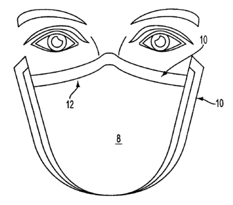
Fig. 7 is a front: view of the mask of the invention attached to the face of a
user.
Fig. 8 is a side view of the mask of the invention attached to the face of a
user.
Fig. 9 is an underside view of the mask of the invention attached to the face
of a user.
CA 02335287 2005-04-27
WO 99/65347 . ' ~ PCT/US99/13513
6
Fig. 10 is a front view of the front sealing sheet in an alternative
embodiment of the invention.
Fig. 11 is a front view of the rear sealing sheet in an alternative
embodiment of the invention.
Fig. 12 is a front view of the mask of an alternative embodiment of the
invention in the sealing structure for the mask.
Fig. 13 is a section view, not drawn to scale, through Section 13-13 of Fig.
12.
Fig. 14 is an exploded view of the alternative embodiment of the mask of
the invention.
Fig. 1 ~ is a front view of a blister-pack storage structure for the mask of
the
invention.
Fig. 16 is a side view of the storage structure shown in Fig. 15.
Fig. 17 is a front view of an alternative blister-pack storage structure for
the
mask of the invention.
Fig. 18 is a side view of the storage structure shown in Fig. 17.
DETAILED DESCRIPTION OF THE INVENTION
Referring to Figs. 1-6, the smoke mask of the invention includes a mask
portion 2, adapted to be worn by a user in the presence of smoke to reduce
smoke
inhalation, and first and second sealing sheets 4 and 6 which form a pull-
apart storage
structure to seal mask portion 2 in an air and moisture impermeable package
prior to use.
In order to provide filtration of smoke particles, mask portion 2 includes a
breathable mask 8, which is preferably constructed of 100% cotton 10 oz. terry
cloth
material. In the alternative, mask 8 may be constructed of any single or mufti-
layered
material. such as paper or a fibrous material, that is breathable and moisture
absorptive,
and that is resistant to breakdown in the presence of moisture. Various other
types of
filters are shown, for example, in the U.S. patents discussed above,
A flexible strip 12, is attached to mask 8 by
adhesive or the like to facilitate securing the mask to the bridge of the nose
of the user, as
described below. Flexible strip 12 is preferably a thin strip of metal, of the
type known in
CA 02335287 2000-12-15
WO 99165347 PCT/US99113513
7
the face mask field for this purpose. Alternatively, any appropriate flexible
material may
be used provided that it serves the function of securing mask 8 to the nose of
the user.
Flexible strip 12 may be secured to either surface of mask 8, or between the
layers of mask
8 if a mufti-layer structure is used.
Mask 8 is preferably rectangular-shaped, as shown in Fig. 1. Nonetheless,
mask 8 may be constructed of any shape, provided that it is sized sufficiently
to allow the
user to breath when in use. For example, mask 8 may be more triangular shaped,
which
provides a more intuitive visual appearance to the user as to the proper way
to attach the
mask to the face.
Mask 8 is stored in a moistened condition, so that it will be immediately
available for use by a user in a smoky condition. The mask is preferably
moistened with
water, either alone or in combination with other substances. In a preferred
embodiment,
mask 8 is also moistened with aloe, glycerin, and/or corn syrup, alone or in
desired
combinations. These substances are preferred to minimize the likelihood of
face chapping
when using the mask. Alternatively, various other substances, such as those
disclosed in
U.S. Patent No. 5,322.060, rnay be utilized within the mask to neutralize the
smoke, to
filter particulates, or to serve any other useful function.
Disposed along an outer peripheral edge and secured to mask 8 is an
attachment lip 10. Attachment lip 10 is preferably constructed of a flexible
sheet plastic
material or the like, which is secured to mask 8 by an adhesive that will not
degrade in the
presence of moisture, by stitching, or by other appropriate attachment means.
Attachment
lip 10 is coated on one side thereof with a pressure sensitive adhesive 20 of
the type
suitable for adhesion to human skin and releasable from the skin without
injury. The
adhesive is preferably hydrophobic in order to allow attachment to the skin
even in the
presence of moisture, from sweat or the like, that might be present on the
skin in a smoke
condition. In lieu of attachment lip 10, adhesive 20 rnay be located on mask 8
itself, either
directly, or secured thereto ora a sheet material. such as a two-sided tape.
For example,
one-side of a two-sided tape rnay be exposed and secured to the outer
periphery of mask 8
during manufacture, preferably prior to moistening of the mask. The other side
of the two-
sided tape, which is coated wiith the hydrophobic pressure sensitive adhesive
is exposed
only during use of the mask, as discussed in detail below. Other alternatives
include. for
CA 02335287 2000-12-15
WO 99165347 PCT/US99113513
8
example, stitching a one-sided tape to mask 8, with the adhesive side of the
tape only
exposed during use, or attaclnnent of two-sided tape to attachment lip 10.
Attachment lip 10 includes a number of slits 14 cut therein, as shown in
Fig. 1, which may extend into mask 8 if desired. Slits 14 are provided in
order to improve
the fit of mask 8 on the face during use by preventing bunching of the mask
due to the
irregular facial features. Slits 14 permit the otherwise flat mask 8 to be
fitted tightly to the
face, as shown in Figs. 7-9. During use, the adhesive: on attachment lip 10 is
exposed, as
discussed below. ThP mask is applied to the face, with flexible strip 12 being
bent to
secure the mask portion to the bridge of the nose. Attachment lip 10 includes
upstanding
portions 16 and 18, which are pressed against the cheeks for adhesive 20 to
attach thereto.
Upstanding portions 16 and l8 include one or more slits 14 extending
therethrough, which
become slightly overlapped when the mask is applied to the cheeks t~ adjust to
the
curvature and contour of the face {not shown in Figs. 7-9). Attachment lip 10
also
includes a lateral portion 22, which is folded under the chin, and secured
thereto by
adhesive 20. In areas where bunching would normally occur, slits 14 are
overlapped by
the wearer to create a tight seal where attachment lip 10 is secured to the
chin and cheeks.
While flexible strip 12 provides a relatively tight fit of mask 8 to the
bridge of the nose, if
desired, attachment lip 10 may be extended laterally along the portion of the
mask having
flexible strip 12, thereby providing an adhesive attachment of the mask to the
face along
the entire periphery of the mask. If an attachment lip is not used, the slits
may be cut in
mask 8 itself.
Sealing sheets 4 and 6 together constitute a pull apart package for storing
mask portion 2 until use. An outex peripheral edge 24 of each sealing sheet is
sealingly
attached to the outer peripheral edge of the other sealing sheet during
manufacture to
create an air and water-tight cavity between the sheets, in which mascC 8 is
stored until use.
Mask 8 is pre-moistened before manufacture so that it is stored in a wetted
condition.
Sealing sheets 4 and 6 may bc: sealed together on their outer peripheral edges
24 by any
appropriate sealing means 30., including pressure-sensitive, heat activated,
or other
adhesive, hot-glue, sonic welding, etc., provided that the sheets form an air
and water-tight
seal, and the sheets may be pulled apart with moderate physical pressure,
preferably so
that the pull-apart structure may be opened by a child. Sealing sheets 4 and 6
are
CA 02335287 2000-12-15
WO 99/65347 PCT/US99/13513
9
preferably constructed of a translucent plastic, although any appropriate
material may be
used.
Each ofthe scaling sheeta 4 and 6 preferably includes a pull tab 28 that
enables the sealing sheets to be pulled apart and separated for use of mask
portion 2. Pull
tabs 28 are preferably integrally constructed with sealing sheets 4 and 6 and
are formed by
extending the peripheral edges of sheets 4 and 6 somewhat beyond outer
peripheral edge
24, at which the sealing sheets are attached to one another. It is foreseen
that tabs 28 may
be separately attached to sealing sheets 4 and 6, or that alternative
strictures to pull apart
the sealing sheets, e.g., pull cords, may be used.
One of the sealing sheets, in this case sealing sheet 4, is adapted to enable
adhesive 20 to be exposed once the pull-apart structure is opened. In one
embodiment of
the invention, as shown in Fig. 4, adhesive 20 is covered by a release sheet
covering 26,
which is pulled from adhesive 20 to expose the adhesive. This type of release
sheet
covering is well known. In the invention, the side of the release sheet facing
adhesive 20
is coated with, or constructed of, a material that releases from the adhesive
when pulled
therefrom. The other side of the release sheet covering is attached to sealing
sheet 4 by
any conventional means, such as with water-proof adhesive. After sealing
sheets 4 and 6
are pulled apart, mask 8 will be Left attached to sealing sheet 4 by release
sheet covering
26. Mask 8 is then be pulled from sealing sheet 4, causing release sheet
covering 26 to
separate from adhesive 20, thereby exposing the adhesive and rendering the
mask ready
for use. It will be appreciated that the storage and release mechanism of the
invention may
be utilized with a mask of an,y size or shape, whether or not the mask
includes slits 14.
Alternatively, it is foreseen that sealing sheet 4 may itself be used to cover
adhesive 20 until use. In this embodiment, sealing sheet 4 may be covered on
the portion
thereof in contact with adhesiive 20 by a release material, and pressed
against adhesive 20
during manufacture to seal the adhesive. It will be appreciated that any
appropriate
material that releases from adhesive 20 rnay be used to coat sealing sheet 4,
or sealing
sheet 4 may be constructed in its entirety of a release sheet, provided that
sealing sheet 4 is
still capable of being attached to sealing sheet 6 to form the pull-apart
structure.
In an alternative embodiment of the invention, as shown in Figs. 10-14, the
smoke mask includes a mask portion 32 and front and rear sealing sheets, 34
and 36
CA 02335287 2005-04-27
_. ~
WO 99/65347 ~ ~ PCT/US99/13513
respectively, which form a pull-apart storage structure to seal mask portion 2
in an air and
moisture impermeable package prior to use. In this embodiment, sealing sheets
34 and 36
seal to mask portion 32 to form the pull-apart structure, rather than sealing
to each other as
in the prior embodiment. Mask 32 is similar to the mask of the prior
embodiment with the
exceptions noted below, and like reference numerals are used to show
corresponding
structures. As in the prior embodiment, mask 8 is stored in a moistened
condition, so that
it will be immediately available for use by a user in a smoky condition.
Secured to mask 8 is an attachment lip 40, which includes those portions of
mask 32 extending peripherally outward from mask 8. as shown in Fig. 14.
Attachment
lip 40 is preferably constructed of a flexible sheet plastic material, which
is secured to
mask 8 by an adhesive that will not degrade in the presence of moisture, by
stitching, or by
other appropriate attachment means. An outer portion 50 of attachment lip 40
is coated on
the side thereof facing rear sealing sheet 36 with a pressure sensitive
adhesive 52 of the
type suitable for adhesion to human skin and releasable from the skin without
injury.
Adhesive 52 is covered by sealing sheet 36, and exposed only when sealing
sheet 36 is
removed just prior.to use.
Attachment lip 40 includes a number of slits 35 cut therein, as in the prior
embodiment, to improve the fit of mask 8 on the face during use. Use of mask 8
is the
same as in the prior embodiment. it being noted that outer portion 50 in this
embodiment
extends further up the cheeks than in the prior embodiment.
Sealing sheets 34 and 36 together constitute a pull apart package for storing
mask portion 32 until use. Each of the sealing sheets 34 and 36 includes a
sealing area 56
which includes an adhesive on the side thereof facing mask portion 32. Sealing
area 56 of
each sealing sheet is sealingly attached to a corresponding sealing area 58 on
mask portion
32 during manufacture to create an air and water-tight cavity between the
sheets, in which
mask 8 is stored until use. Along a portion of mask 8 above flexible strip 12
over which
peripheral lip 40 does not extend, sealing areas 56 of the sealing sheers seal
to each other
to complete the air and watertight seal of mask portion 32. If desired.
peripheral lip 40
may be extended completely around mask 8 to eliminate the sealing of sealing
sheets 34
and 36 to each other. Sealing sheets 34 and 36 are sealed to mask portion 32
and to each
other by any appropriate sealing means 60, including pressure-sensitive, heat
activated, or
CA 02335287 2000-12-15
WO 99/65347 PCT/US99/13513
11
other adhesive, hot-glue, saruic welding, etc., Sealing sheets 34 and 36 are
preferably
constructed of a translucent plastic. Each of the sealing sheets 34 and 36
preferably
includes a pull tab 28 that enables the sealing sheets to be pulled apart and
separated for
use of mask portion 32.
One of the sealing sheets, in this case rear sealing sheet 36, is adapted to
enable adhesive 52 to be exposed once the pull-apart structure is opened.
Adhesive 52 is
covered by a release sheet covering 66, which is pulled from adhesive 52 to
expose the
adhesive. The side of the release sheet facing adhesive 52 is coated with, or
constructed
of, a material that releases from the adhesive when pulled therefronn. 'the
other side of the
release sheet covering 66 is attached to sealing sheet 36 by any conventional
means, such
as with adhesive. When sealing sheets 34 and 36 are pulled apart, mask 8 will
be pulled
from sealing sheet 36, causirug release sheet covering 66 to separate from
adhesive 52,
thereby exposing the adhesive and rendering the mask ready for use. It is
foreseen that
sealing sheet 36 may itself bc~ used to cover adhesive 52 until use by
covering the portion
thereof in contact with adhesive 52 with a release material.
Figs. 15-18 shown an alternative storage structure 100 for mask 32.
Storage structure 100 is generally a conventional blister-pack storage
structure consisting
of a backing 102 and a cover portion 104. Backing 102 is preferably
constructed of a
cardboard or other material that is covered in printed material associated
with mask 32.
On the portion of backing I 02 facing mask portion 32, backing 102 is
preferably covered
with a film of plastic or other waterproof material to prevent degradation of
backing 102
from the moist enviromnent in which mask 32 is stored, and to keen :.torage
structure 100
water impermeable.
Cover 104 is preferably constructed of a vacuum formed plastic or other
water impermeable material, and is preferably translucent to enable mask 32 to
be seen
from the exterior of storage structure 100. Cover 104 defines an interior
cavity in which
mask 32 is stored until use. (over 104 is secured to backing 102 using any
conventional
water-proof adhesive that allows mask 32 to remain in a water-tight
environment and that
would allow the storage structure to be opened without undue manipulation in
the event
mask 32 is needed for use. A.s shown in Figs. 15 and 16, cover 104 preferably
includes a
lip portion 106 running along at least one edge thereof, preferably along the
entire edge.
CA 02335287 2000-12-15
WO 99/65347 PCT/US99/13513
12
Lip portion I06 is preferably sized so that the lip may be grasped by a user
and pulled
away from backing 102 to rapidly open storage structure 100 in an emergency.
Lip
portion 106 is preferably integrally formed with cover 104. In an altf~rnative
embodiment,
as shown in Figs. 17 and 18, a tab 108 is attached to cover 104, preferably by
being
integrally formed therewith. To open storage structure 100, a user, while
holding backing
102, pulls tab 108 with sufficient farce to overcome the adhesive bond between
cover 104
and backing 102, or to enablf: the plastic, coating on backing 102 to tear
away from or
separate from the backing. Ii: is foreseen that other opening mechanisms may
be utilized
in connection with storage structure 100, and that other alternative storage
structures for
mask 32 may be used as well.
On the side thereof facing backing 102, an outer peripheral edge of mask
32 is coated with an adhesive: of the type described above to enable the mask
to be applied
to the face of a user. Backing; 102 preferably includes a release tape on the
surface thereof
facing mask 32 so that the mask is attached to the release tape on backing
102. In use,
once storage structure 100 is opened, mask 32 remains attached to backing 102,
and may
be used by pulling mask 32 off of the release tape, thereby exposing the
adhesive on mask
32. It is foreseen that mask :32 may be mounted to any wall of the cavity
formed by cover
104 and backing 102, so that, for example, mask 32 may remain attached to
cover 104
when structure I 00 is opened. If desired, protuberances 110 may be included
on cover
104. Protuberances 110, which may be mounted to or integral with cover 104,
apply
pressure to mask 32 to maintan the adhesive on mask 32 in contact with the
release tape
on backing 102 in order to preserve the adherence of the adhesive.
Although the present invention has been described in detail with respect to
certain embodiments and examples, variations and modifications exist that are
within the
scope of the invention as defined in the following claims.
What is claimed is as follows: